ANI-42HPIPX - Router A-NeuVideo - Free user manual and instructions
Find the device manual for free ANI-42HPIPX A-NeuVideo in PDF.

User questions about ANI-42HPIPX A-NeuVideo
0 question about this device. Answer the ones you know or ask your own.
Ask a new question about this device
Download the instructions for your Router in PDF format for free! Find your manual ANI-42HPIPX - A-NeuVideo and take your electronic device back in hand. On this page are published all the documents necessary for the use of your device. ANI-42HPIPX by A-NeuVideo.
USER MANUAL ANI-42HPIPX A-NeuVideo
UHD+ 4x2 HDMI Matrix with PiP

text_image
TAA COMPLIANT IN COMPLIANCE WITH THE TRADE AGREEMENTS ACT A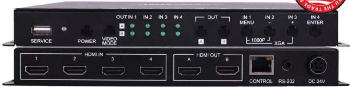
text_image
OUT IN 1 IN 2 IN 3 IN 4 OUT IN 1 IN 2 IN 3 IN 4 A B SERVICE POWER VIDEO MODE A B 1080P XGA HDMI IN 3 4 HDMI OUT CONTROL RS-232 DC 24VPACKAGE CONTENTS
Before attempting to use this unit, please check the packaging and make sure the following items are contained in the box:
• ANI-42HPIPX UHD+ 4x2 HDMI Matrix with PiP
• 24V/2.7A DC Power Adapter
- Rackmount Ears (Set of 2)
- Shockproof Feet (Set of 4)

SAFETY INFORMATION

-
To ensure the best results from this product, please read this manual and all other documentation before operating your equipment. Retain all documentation for future reference.
-
Follow all instructions printed on unit chassis for proper operation.
-
To reduce the risk of fire, do not spill water or other liquids into or on the unit, or operate the unit while standing in liquid.
-
Make sure power outlets conform to the power requirements listed on the back of the unit. Keep unit protected from rain, water and excessive moisture.
-
Do not attempt to clean the unit with chemical solvents or aerosol cleaners, as this may damage the unit. Dust with a clean dry cloth.
-
Do not use the unit if the electrical power cord is frayed or broken. The power supply cords should be routed so that they are not likely to be walked on or pinched by items placed upon or against them, paying particular attention to cords and plugs, convenience receptacles, and the point where they exit from the appliance.
-
Do not force switched or external connections in any way. They should all connect easily, without needing to be forced.
-
Always operate the unit with the AC ground wire connected to the electrical system ground. Precautions should be taken so that the means of grounding of a piece of equipment is not defeated.
-
AC voltage must be correct and the same as that printed on the rear of the unit. Damage caused by connection to improper AC voltage is not covered by any warranty.
-
Turn power off and disconnect unit from AC current before making connections.
-
Never hold a power switch in the "ON" position.
-
This unit should be installed in a cool dry place, away from sources of excessive heat, vibration, dust, moisture and cold. Do not use the unit near stoves, heat registers, radiators, or other heat producing devices.
-
Do not block fan intake or exhaust ports. Do not operate equipment on a surface or in an environment which may impede the normal flow of air around the unit, such as a bed, rug, carpet, or completely enclosed rack. If the unit is used in an extremely dusty or smoky environment, the unit should be periodically "blown free" of foreign dust and matter.
-
To reduce the risk of electric shock, do not remove the cover. There are no user serviceable parts inside. Refer all servicing to qualified service personnel. There are no user serviceable parts inside.
-
When moving the unit, disconnect input ports first, then remove the power cable; finally, disconnect the interconnecting cables to other devices.
-
Do not drive the inputs with a signal level greater than that required to drive equipment to full output.
-
The equipment power cord should be unplugged from the outlet when left unused for a long period of time.
-
Save the carton and packing material even if the equipment has arrived in good condition. Should you ever need to ship the unit, use only the original factory packing.
-
Service Information Equipment should be serviced by qualified service personnel when:
A. The power supply cord or the plug has been damaged.
B. Objects have fallen, or liquid has been spilled into the equipment.
C. The equipment has been exposed to rain.
D. The equipment does not appear to operate normally, or exhibits a marked change in performance.
E. The equipment has been dropped, or the enclosure damaged.
CONTENTS
INTRODUCTION....1
FEATURES/APPLICATIONS/SYSTEM REQUIREMENTS ....2
SPECIFICATIONS / CABLE SPECIFICATIONS ....3
OPERATION CONTROLS & FUNCTIONS ....4
FRONT PANEL 4
REAR PANEL 5
RS-232 CONTROL / TELNET CONTROL 6
OSD MENU 14
WEBGUI CONTROL 23
CONNECTION DIAGRAM 29
VIDEO SPECIFICATIONS 30
AUDIO SPECIFICATIONS 31
DEAR CUSTOMER
Thank you for purchasing this product. For optimum performance and safety, please read these instructions carefully before connecting, operating or adjusting this product. Please keep this manual for future reference.
INTRODUCTION
The ANI-42HPIPX This 4x2 HDMI Matrix with PiP is a high performance HDMI switch with integrated scaling and multi-windowing technology which can connect up to (4) 4K UHD+ HDMI sources to up to (2) 4K UHD+ HDMI displays and freely switch between them. It is an ideal solution for monitoring or displaying multiple sources simultaneously for use in control rooms, conference rooms or classrooms. Video resolutions up to 4K@60Hz and LPCM audio up to 7.1 channels at 192KHz are supported and this unit is fully compatible with the HDCP 1.x and 2.2 standards.
Any of (4) different HDMI sources may be displayed individually full screen, with seamless switching in Matrix mode, or they can be displayed using a variety of multi-window modes including standard views like PiP (Picture in Picture) and PoP (Picture outside of Picture) as well as fully customizable quad-window modes. Control of input/window routing, position and sizing is easy using the front panel controls with OSD menu as well as by WebGUI, RS-232, and Telnet. This product has a 3 year warranty.
SAFETY PRECAUTIONS
Please read all instructions before attempting to unpack, install or operate this equipment and before connecting the power supply. Please keep the following in mind as you unpack and install this equipment:
- Always follow basic safety precautions to reduce the risk of fire, electrical shock and injury to persons.
- To prevent fire or shock hazard, do not expose the unit to rain, moisture or install this product near water.
- Never spill liquid of any kind on or into this product.
- Never push an object of any kind into this product through any openings or empty slots in the unit, as you may damage parts inside the unit.
- Do not attach the power supply cabling to building surfaces.
- Use only the supplied power supply unit (PSU). Do not use the PSU if it is damaged.
- Do not allow anything to rest on the power cabling or allow any weight to be placed upon it or any person walk on it.
- To protect the unit from overheating, do not block any vents or openings in the unit housing that provide ventilation and allow for sufficient space for air to circulate around the unit.
DISCLAIMERS
The information in this manual has been carefully checked and is believed to be accurate. We assume no responsibility for any infringements of patents or other rights of third parties which may result from its use.
We assume no responsibility for any inaccuracies that may be contained in this document. We make no commitment to update or to keep current the information contained in this document.
We reserve the right to make improvements to this document and/or product at any time and without notice.
COPYRIGHT NOTICE
No part of this document may be reproduced, transmitted, transcribed, stored in a retrieval system, or any of its part translated into any language or computer file, in any form or by any means — electronic, mechanical, magnetic, optical, chemical, manual, or otherwise — without the express written permission and consent.
© Copyright 2022. All Rights Reserved.
Version 1.2 JULY 2022
TRADEMARK ACKNOWLEDGMENTS
All products or service names mentioned in this document may be trademarks of the companies with which they are associated.
FEATURES
- HDMI 2.0 and DVI 1.0 compliant (with the use of an HDMI-DVI adapter)
• HDCP 1.x and 2.2 compliant
• (4) HDMI inputs and (2) HDMI outputs
• Supports up to 4K UHD+ (18Gbps, 4K@50/60Hz 4:4:4, 8bit) video input and output - Seamless switching (no loss of sync to display) when switching sources in Matrix mode
- Supports up to (4) simultaneous, freely scalable, windows in multiwindowing modes
• Supports the ability to store a multi-window arrangement as a preset that can be recalled later - Independent audio source selection and routing in all modes
- Inputs 1 & 2 support pass-through of many audio formats including 8 channel LPCM, Bitstream, and HD Bitstream (Inputs 3 & 4 are limited to 2 channel LPCM only)
• Each window can have a border with a selectable color - Uploadable and freely positionable graphic logo support
- Intuitive and easy adjustment of window size, position and settings in multi-window modes via the WebGUI
• Per-input EDID management with internal or external EDID options - Controllable via front panel buttons, WebGUI, Telnet, and RS-232
APPLICATIONS
- Entertainment Room & Home Theater
• Show Room & Demo Room - Lecture Room & Hall Presentation
• Public Commercial Display
SYSTEM REQUIREMENTS
- HDMI source equipment such as media players, video game consoles or set-top boxes.
- HDMI receiving equipment such as HDTVs, monitors or audio amplifiers.
SPECIFICATIONS
• HDMI Bandwidth: 18Gbps
• Input Ports: (4) HDMI (Type-A)
• Output Ports: (2) HDMI (Type-A)
- Control Ports:
- RS-232 (3.5mm)
• IP Control (RJ-45)
• Service Port: USB 2.0 (Type A)
- Baud Rate: 19200
• Power Supply: 24V/2.7A DC (US/EU standards, CE/FCC/UL certified)
• ESD Protection (HBM):
- ±8kV (Air Discharge)
- ±4kV (Contact Discharge)
- Dimensions (WxHxD): 9.1 x 1 x 6.2 in (231.5x25x158mm) [Case Only] / 9.1 x 1 x 6.3 in (231.5x25x161mm) [All Inclusive]
• Weight: 2.1 lb / 968g
• Chassis Material: Metal (Steel)
- Chassis Color: Black
- Operating Temperature: 0^ - 40^ / 32^ - 104^
• Storage Temperature: -20^ - 60^ / -4^ - 140^
- Relative Humidity: 20 – 90% RH (Non-condensing)
• Power Consumption: 15.3W
As product improvements are continuous, specifications are subject to change without notice.
CABLE SPECIFICATIONS
| Cable Length | 1080p 4K30 4K60 | |||
| 8bit 12bit (4:4:4) 8bit (4:4:4) 8bit | ||||
| High Speed HDMI Cable | ||||
| HDMI Input 49 ft / 15M 33 ft / | 10M 16 ft / 5M 10 ft / 3M | |||
| HDMI Output 49 ft / 15M 33 ft / | 10M 16 ft / 5M 10 ft / 3M | |||
Bandwidth Category Examples:
• 1080p (FHD Video)
- Up to 1080p@60Hz, 12bit color
• Data rates lower than 5.3Gbps or below 225MHz TMDS clock
• 4K30 (4K UHD Video)
• 4K@24/25/30Hz & 4K@50/60Hz (4:2:0), 8bit color
• Data rates higher than 5.3Gbps or above 225MHz TMDS clock but below 10.2Gbps
• 4K60 (4K UHD+ Video)
• 4K@50/60Hz (4:4:4, 8bit)
• 4K@50/60Hz (4:2:0, 10bit HDR)
• Data rates higher than 10.2Gbps
FRONT PANEL

text_image
SER/ICE POWER VIDEO MODE OUT IN 1 IN 2 IN 3 IN 4 A B OUT A B IN 1 MENU IN 2 IN 3 IN 4 1080P XGA 1 2 3 4 5 6 7 8 9① SERVICE PORT: This port is reserved for firmware update and user EDID/logo upload use only.
2 POWER LED & BUTTON: Press this button to power the unit on (green LED) or place it into stand-by mode (red LED).
Note: Ethernet and RS-232 remain active when the unit is in stand-by mode.
3 VIDEO MODE BUTTON: Press this button to sequentially switch the unit's operational mode between Matrix, PiP, PoP, and Quad.
④ OUT A\~B/IN 1\~4 LED ARRAY: In Matrix mode, these LED's indicate the currently selected sources (IN 1\~4) routed to each of the (2) outputs (OUT A\~B). When the unit is in a multi-windowing mode (PiP/PoP/Quad/Preset) all LEDs will be illuminated simultaneously.
Note: When source selection is active the associated output's LED(s) will blink.
5 OUT A/B BUTTONS: In Matrix mode, either of these buttons to activate/deactivate discrete source selection for the associated output. In multiwindowing modes (PiP/PoP/Quad/Preset) either button will activate/deactivate sequential source selection for the (4) windows.
Note: These buttons only activate/deactivate the ability to change sources. Actual source selection is accomplished using the IN 1\~4 buttons.
6 IN 1/MENU BUTTON: When not in source selection mode, press to enter the OSD menu, or to back out from menu items. When source selection is active, pressing this button will either select input 1 (Matrix mode) or sequentially switch through all (4) inputs for window 1 (PiP/PoP/Quad/Preset modes).
Note: Pressing "MENU" and "+" together will reset the output resolution to XGA (1024x768@60Hz). Pressing "MENU" and "-" together will reset the output resolution to 1080p@60Hz.
7 IN 2/- (MINUS) BUTTON: When not in source selection mode, press to move down or adjust selections within OSD menus. When source selection is active, pressing this button will either select input 2 (Matrix mode) or sequentially switch through all (4) inputs for window 2 (PiP/PoP/Quad/Preset modes).
8 IN 3/+ (PLUS) BUTTON: When not in source selection mode, press to move up or adjust selections within OSD menus. When source selection is active, pressing this button will either select input 3 (Matrix mode) or sequentially switch through all (4) inputs for window 3 (PiP/PoP/Quad/Preset modes).
9 IN 4/ENTER BUTTON: When not in source selection mode, press to confirm a selection within the OSD or to go deeper into a menu item. When source selection is active, pressing this button will either select input 4 (Matrix mode) or sequentially switch through all (4) inputs for window 4 (PiP/PoP/Quad/Preset modes).
BACK PANEL

text_image
HDMI IN 1 2 3 4 HDMI OUT A B CON'ROL RS-232 DC 24V 1 2 3 4 5① HDMI IN 1\~4 PORTS: Connect to HDMI source equipment such as media players, game consoles, or set-top boxes.
Note: Audio support on inputs 3\~4 is limited to 2 channel LPCM.
② HDMI OUT A\~B PORTS: Connect to HDMI TVs, monitors, or amplifiers for digital video and audio output.
3 CONTROL PORT: Connect directly, or through a network switch, to your PC/laptop to control the unit via Telnet/WebGUI.
4 RS-232 PORT: Connect directly to a PC, laptop, or other serial control device with a 3.5mm adapter cable to send RS-232 commands to control the unit.
⑤ DC 24V PORT: Plug the 24V DC power adapter into this port and connect it to an AC wall outlet for power.
RS-232 PINOUT & DEFAULTS
| SERIAL PORT DEFAULT SETTINGS | |
| BAUD RATE 19200 | |
| Data Bits 8 | |
| Parity Bits None | |
| Stop Bits 1 | |
| Flow Control None | |
3.5mm to DE-9 Adapter Cable

text_image
1 TxD 2 RxD 3 GNDTELNET CONTROL
Before attempting to use Telnet control, please ensure that both the unit and the PC are connected to the same active networks.
| TO ACCESS THE COMMAND LINE INTERFACE (CLI) | |
| Windows 7 | Click START, type “cmd” in the search field and press ENTER. |
| Windows 10 1. Open “Control Panel”. | 2. Open “Programs and Features“.3. Select the “Turn Windows features on or off” option. |
| 4. Check the “Telnet Client” box.5. Click “OK“. A box will appear that says “Windows Features” and “Searching for required files“. When complete, the Telnet client should be installed in Windows. | |
| Mac OS X Click Go > Applications > Utilities > Terminal. | |
Once in the Command Line Interface (CLI) type “telnet” followed by the IP address of the unit (and the port number if it is non-standard) and then hit “Enter”. This will connect us to the unit we wish to control.
Microsoft Windows [Version 6.1.7601]
Copyright (c) 2009 Microsoft Corporation. All rights reserved.
C:\Users\Administrator>telnet 192.168.1.50 23
Note 1: If the IP address is changed then the IP address required for Telnet access will also change accordingly.
Note 2: The default IP address is 192.168.1.50.
SERIAL & TELNET COMMANDS
| COMMAND DESCRIPTION | ||
| HELP ← | Show the full command list. | |
| HELP N1 ← | Show details about the specified command.N1 = {Command} | |
| ? ← | Show the full command list. | |
| ? N1 ← | Show details about the specified command.N1 = {Command} | |
| GET FW VER ← | Show the unit's current firmware version. | |
| GET COMMAND VER ← | Show the unit's current command version. | |
| GET MAC ADDR ← | Show the unit's MAC address. | |
| GET MODEL NAME ← | Show the unit's model name. | |
| GET MODEL TYPE ← | Show the unit's product type. | |
| SET FEEDBACK BROADCAST N1 ← | Enable or disable the broadcast of console command feedback.Available values for N1:ON [Enabled]OFF [Disabled] | |
| GET FEEDBACK BROADCAST ← | Show the current console command feedback broadcast state. | |
| SET IP MODE N1 ← | Set the IP address assignment mode.Available values for N1:STATIC [Static IP mode]DHCP [DHCP mode] | |
| GET IP MODE ← | Show the current IP address assignment mode. | |
| GET IPCONFIG ← | Show the unit's current IP configuration information. | |
| GET IPADDR ← | Show the unit's current IP address. | |
| GET NETMASK ← | Show the unit's current netmask. | |
| GET GATEWAY ← | Show the unit's current gateway address. | |
| SET STATIC IPADDR N1 ← | Set the unit's static IP address.N1 = X.X.X.X [X = 0~255, IP address] | |
| GET STATIC IPADDR ← | Show the unit's static IP address. | |
| SET STATIC NETMASK N1 ← | Set the unit's static IP address.N1 = X.X.X.X [X = 0~255, Netmask] | |
| GET STATIC NETMASK ← | Show the unit's static netmask. | |
| SET STATIC GATEWAY N1 ← | Set the unit's static IP address.N1 = X.X.X.X [X = 0~255, Gateway address] | |
| GET STATIC GATEWAY ← | Show the unit's static gateway address. | |
| SET WEBGUI USERNAME N1 ← | Set the WebGUI login username.N1 = {Username} [16 characters max] | |
| GET WEBGUI USERNAME ← | Show the current WebGUI login username. | |
| SET WEBGUI PASSWORD N1 ← | Set the WebGUI login password.N1 = {Password} [16 characters max] | |
| GET WEBGUI PASSWORD ← | Show the current WebGUI login password. | |
| SET WEBGUI LOGIN TIMEOUT N1 ← | Set the WebGUI inactivity timeout value.N1 = 0~240 [Minutes] | |
| GET WEBGUI LOGIN TIMEOUT ← | Show the current WebGUI inactivity timeout value. | |
| SET TELNET LOGIN N1 ← | Enable or disable allowing Telnet logins.Available values for N1:ON [Enabled]OFF [Disabled] | |
| GET TELNET LOGIN ← | Show the current state of Telnet login allowance. | |
| SET TELNET USERNAME N1 ← | Set the Telnet login username.N1 = {Username} [16 characters max] | |
| GET TELNET USERNAME ← | Show the current Telnet login username. | |
| SET TELNET PASSWORD N1 ← | Set the Telnet login password.N1 = {Password} [16 characters max] | |
| GET TELNET PASSWORD ← | Show the unit's Telnet access port. | |
| SET WINDOW LAYOUT MODE N1 ← | Set the window layout mode.Available values for N1:0 [Matrix mode]1 [PiP mode]2 [PoP mode] | 3 [Quad mode]4 [Preset 1]5 [Preset 2]6 [Preset 3]7 [Preset 4] |
| GET WINDOW LAYOUT MODE ← | Show the window current layout mode. | |
| SET WINDOW N1 ROUTE N2 ← | Set the input to route to the specified window.N1 = 1~4 [Window number]N2 = 1~4 [Input port]Note: Valid in multi-windowing modes only. | |
| GET WINDOW N1 ROUTE ← | Show the input currently routed to the specified window.N1 = 1~4 [Window number]Note: Valid in multi-windowing modes only. | |
| SET OUT N1 ROUTE N2 ← | Route the specified input to the specified output.N1 = A~B [Output port]N2 = 1~4 [Input port]Note: Valid in matrix mode only. | |
| GET OUT N1 ROUTE ← | Show the current input routed to the specified output.N1 = A~B [Output port]Note: Valid in matrix mode only. | |
| SET WINDOW N1 DISPLAY N2 ← | Enable or disable the specified window.N1 = 1~4 [Window number]Available values for N2:ON [Enabled]OFF [Disabled]Note: Valid in multi-windowing modes only. | |
| GET WINDOW N1 DISPLAY ← | Show the visibility status of the specified window.N1 = 1~4 [Window number]Note: Valid in multi-windowing modes only. | |
| SET WINDOW N1 HPOSITION N2 ← | Set the horizontal position of the specified window.N1 = 1~4 [Window number]N2 = 0~{Max res} [Horizontal size]Note: Valid in multi-windowing modes only. | |
| GET WINDOW N1 HPOSITION ← | Show the current horizontal position of the specified window.N1 = 1~4 [Window number]Note: Valid in multi-windowing modes only. | |
| SET WINDOW N1 VPOSITION N2 ← | Set the vertical position of the specified window.N1 = 1~4 [Window number]N1 = 0~{Max res} [Vertical size]Note: Valid in multi-windowing modes only. | |
| GET WINDOW N1 VPOSITION ← | Show the current vertical position of the specified window.N1 = 1~4 [Window number]Note: Valid in multi-windowing modes only. | |
| SET WINDOW N1 HSIZE N2 ← | Set the horizontal size of the specified window.N1 = 1~4 [Window number]N1 = 1~{Max res} [Horizontal size]Note: Valid in multi-windowing modes only. | |
| GET WINDOW N1 HSIZE ← | Show the current horizontal size of the specified window.N1 = 1~4 [Window number]Note: Valid in multi-windowing modes only. | |
| SET WINDOW N1 VSIZE N2 ← | Set the vertical size of the specified window.N1 = 1~4 [Window number]N1 = 1~{Max res} [Vertical size]Note: Valid in multi-windowing modes only. | |
| GET WINDOW N1 VSIZE ← | Show the current vertical size of the specified window.N1 = 1~4 [Window number]Note: Valid in multi-windowing modes only. | |
| SET WINDOW N1 PRIORITY N2 ← | Set the priority of the specified window.N1 = 1~4 [Window number]N1 = 1~4 [Priority]Note: Valid in multi-windowing modes only. | |
| GET WINDOW N1 PRIORITY ← | Show the current priority of the specified window.N1 = 1~4 [Window number]Note: Valid in multi-windowing modes only. | |
| SET WINDOW N1 ASPECT N2 ← | Set the aspect of the specified window.N1 = 1~4 [Window number]Available values for N2:1 [Full]2 [16:9] | 3 [16:10]4 [4:3]5 [Best Fit]6 [User] |
| GET WINDOW N1 ASPECT ← | Show the current aspect of the specified window.N1 = 1~4 [Window number] | |
| SET WINDOW N1 MIRROR N2 ← | Set the mirror mode of the specified window.N1 = 1~4 [Window number]Available values for N2:ON [Enabled]OFF [Disabled] | |
| GET WINDOW N1 MIRROR ← | Show the current mirror mode of the specified window.N1 = 1~4 [Window number] | |
| SET WINDOW N1 BORDER N2 ← | Set the border mode of the specified window.N1 = 1~4 [Window number]Available values for N2:ON [Enabled]OFF [Disabled] | |
| GET WINDOW N1 BORDER ← | Show the current border mode of the specified window. | |
| SET WINDOW N1 BORDER COLOR N2 ↩ | Set the border color of the specified window.N1 = 1~4 [Window number]Available values for N2:1 [Black]2 [Red]3 [Green]4 [Blue]5 [Yellow]6 [Magenta] | 7 [Cyan]8 [White]9 [Dark Red]10 [Dark Green]11 [Dark Blue]12 [Dark Yellow]13 [Dark Magenta]14 [Dark Cyan]15 [Gray] |
| GET WINDOW N1 BORDER COLOR ↩ | Show the current border color of the specified window.N1 = 1~4 [Window number] | |
| SET WINDOW N1 RESET ↩ | Reset the settings of the specified windowN1 = 1~4 [Window number] | |
| SET IN N1 CONTRAST N2 ↩ | Set the contrast level of the specified input.N1 = 1~4 [Input port]N2 = 0~100 [Contrast level] | |
| GET IN N1 CONTRAST ↩ | Show the current contrast level of the specified input.N1 = 1~4 [Input port] | |
| SET IN N1 BRIGHTNESS N2 ↩ | Set the brightness level of the specified input.N1 = 1~4 [Input port]N2 = 0~100 [Brightness level] | |
| GET IN N1 BRIGHTNESS ↩ | Show the current brightness level of the specified input.N1 = 1~4 [Input port] | |
| SET IN N1 SATURATION N2 ↩ | Set the saturation level of the specified input.N1 = 1~4 [Input port]N2 = 0~100 [Saturation level] | |
| GET IN N1 SATURATION ↩ | Show the current saturation level of the specified input.N1 = 1~4 [Input port] | |
| SET IN N1 HUE N2 ↩ | Set the hue value of the specified input.N1 = 1~4 [Input port]N2 = 0~100 [Hue value] | |
| GET IN N1 HUE ↩ | Show the current hue value of the specified input.N1 = 1~4 [Input port] | |
| SET IN N1 SHARPNESS H N2 ↩ | Set the horizontal sharpness level of the specified input.N1 = 1~4 [Input port]N2 = 0~20 [Horizontal sharpness level] | |
| GET IN N1 SHARPNESS H ↩ | Show the current horizontal sharpness level of the specified input.N1 = 1~4 [Input port] | |
| SET IN N1 SHARPNESS V N2 ↩ | Set the vertical sharpness level of the specified input.N1 = 1~4 [Input port]N2 = 0~20 [Vertical sharpness level] | |
| GET IN N1 SHARPNESS V ↩ | Show the current vertical sharpness level of the specified input.N1 = 1~4 [Input port] | |
| SET IN N1 PICTURE RESET ↩ | Set the picture settings reset.N1 = 1~4 [Input port] | |
| SET AUDIO OUT N1 MUTE N2 ↩ | Enable or disable muting the specified audio output.N1 = A~B [Output port]Available values for N2:ON [Mute]OFF [Unmute] | |
| COMMAND DESCRIPTION | |||
| SET AUDIO OUT N1 ROUTE N2← | Route the specifiedaudio source to thespecified audio output.N1 = A~B [Output port]Available values for N2: | 1 [Input 1]2 [Input 2]3 [Input 3]4 [Input 4]5 [Window 1] | 6 [Window 2]7 [Window 3]8 [Window 4] |
| GET AUDIO OUT N1 ROUTE← | Show the current audio source routed to the specified audio output.N1 = A~B [Output port] | ||
| SET ALL IN EDID MODE N1← | Select the EDID management mode to use (All or Independent) for all inputs.Available values for N1:1 [All mode]2 [Independent mode] | ||
| GET ALL IN EDID MODE← | Show the current EDID management mode used by all inputs. | ||
| SET ALL IN EDID N1← | Set the EDID to usewhen the “All” EDIDmode is active.Available values for N1:1 [1080p60 2-Channel] | 2 [4Kp30 2-Channel]3 [4Kp60 2-Channel]7 [User 1]8 [User 2]9 [User 3] | 10 [User 4]15 [Sink A]16 [Sink B] |
| GET ALL IN EDID← | Show the current EDID used by the “All” EDID mode. | ||
| SET IN N1 EDID N2← | Set the EDID to use onthe specified input.Available values for N1:1 [1080p60 2-Channel] | 2 [4Kp30 2-Channel]3 [4Kp60 2-Channel]7 [User 1]8 [User 2] | 9 [User 3]10 [User 4]15 [Sink A]16 [Sink B] |
| GET IN N1 EDID← | Show the EDID currently being used on the specified input.N1 = 1~4 [Input port] | ||
| SET USER EDID N1 UPDATE← | Upload a new EDID for use as the specified User EDID.N1 = 1~4 [User EDID number] | ||
| SET IN N1 HDCP MODE N2← | Set the HDCP behavior of the specified input.N1 = 1~4 [Input port]Available values for N2:0 [HDCP off]1 [Refer to Source]2 [Refer to Display] | ||
| GET IN N1 HDCP MODE← | Show the current HDCP behavior used by the specified input.N1 = 1~4 [Input port] | ||
| SET OUT A TIMING N1← | Set the output resolutionto use for both outputs.Available values for N1:0 [640x480p59]1 [480p60]2 [576p50]3 [800x600p60]4 [848x480p60]5 [1024x768p60]6 [1280x720p50]7 [1280x720p60]8 [1280x768p60]9 [1280x800p60]10 [1280x960p60] | 11 [1280x1024p60]12 [1360x768p60]13 [1366x768p60]14 [1400x1050p60]15 [1440x900p60]16 [1600x900p60rb]17 [1600x1200p60]18 [1680x1050p60]19 [1920x1080p24]20 [1920x1080p25]21 [1920x1080p30]22 [1920x1080p50]24 [1920x1200rb]25 [2048x1152rb] | 26 [3840x2160p24]27 [3840x2160p25]28 [3840x2160p30]29 [4K p24 DCI]30 [4K p25 DCI]31 [4K p30 DCI]32 [4K p50 DCI]33 [4K p59 DCI]34 [4K p60 DCI]35 [3840x2160p50]36 [3840x2160p59]37 [3840x2160p60]38 [Native OUT A]39 [Native OUT B] |
| GET OUT A TIMING← | Show the current resolution used by both outputs. | ||
| SET OUT A OSD POSITION N1 ↙ | Set the OSD menu location.Available values for N1:0 [Top Left]1 [Top Right]2 [Bottom Right]3 [Bottom Left] | ||
| GET OUT A OSD POSITION ↙ | Show the current OSD menu location. | ||
| SET OUT A OSD TIMEOUT N1 ↙ | Set the OSD menu's timeout value (in seconds).Available values for N1:OFF [Disabled]5~60 [Timeout in seconds] | ||
| GET OUT A OSD TIMEOUT ↙ | Show the current OSD menu's timeout value. | ||
| SET OUT A OSD INFO DISPLAY N1 ↙ | Enable or disable the info OSD.Available values for N1:ON [Enabled]OFF [Disabled] | ||
| GET OUT A OSD INFO DISPLAY ↙ | Show the current info OSD state. | ||
| SET OUT A OSD INFO TIMEOUT N1 ↙ | Set the OSD info's timeout value (in seconds).Available values for N1:OFF [Disabled]5~60 [Timeout in seconds] | ||
| GET OUT A OSD INFO TIMEOUT ↙ | Show the current OSD info's timeout value. | ||
| SET OUT A OSD TRANSPARENCY N1 ↙ | Set the transparency level of the OSD.N1 = 0~10 [Transparency level] | ||
| SET OUT A OSD BACKGROUND COLOR N1 ↙ | Set the color of the background of the OSD banner.Available values for N1:0 [Black]1 [Gray]2 [Blue] | ||
| GET OUT A OSD BACKGROUND COLOR ↙ | Show the current color of the background of the OSD banner on the specified output. | ||
| SET OUT A OSD LOGO DISPLAY N1 ↙ | Enable or disable the graphical logo overlay.Available values for N1:ON [Enabled]OFF [Disabled] | ||
| GET OUT A OSD LOGO DISPLAY ↙ | Show the current state of the graphical logo overlay. | ||
| SET OUT A OSD LOGO HPOSITION N1 ↙ | Set the horizontal position of the graphical logo overlay.N1 = 0~100 [Horizontal position] | ||
| GET OUT A OSD LOGO HPOSITION ↙ | Show the current horizontal position of the graphical logo overlay. | ||
| SET OUT A OSD LOGO VPOSITION N1 ↙ | Set the vertical position of the graphical logo overlay.N1 = 0~100 [Vertical position] | ||
| GET OUT A OSD LOGO VPOSITION ↙ | Show the current vertical position of the graphical logo overlay. | ||
| SET OSD LOGO DEFAULT ↙ | Resets the logo and installs a default test image. | ||
| SET OSD LOGO UPDATE ↙ | Initiates the logo update process via USB. | ||
| SET SAVE PRESET N1 ↙ | Saves the current unit's settings to the specified preset.N1 = 1~4 [Preset number] | ||
| COMMAND DESCRIPTION | ||
| SET AUTO SYNC OFF N1 ← | Enable or disable the Auto Sync Off function and set the timeout length. Available values for N1:0 [Always on]1 [5 seconds]2 [10 seconds]3 [15 seconds]4 [30 seconds] | 5 [1 minutes]6 [1.5 minutes]7 [2 minutes]8 [2.5 minutes]9 [3 minutes]10 [5 minutes]11 [10 minutes] |
| GET AUTO SYNC OFF ← | Show the current Auto Sync Off settings. | |
| SET FIRMWARE UPDATE ← | Initiates the firmware update process via USB. | |
| SET FACTORY USER EDID DEFAULT ← | Restore the unit's User EDIDs to their factory default settings. | |
| SET FACTORY IPCONFIG DEFAULT ← | Reset the unit's network settings to the factory defaults. | |
| SET FACTORY DEFAULT ← | Restore the unit's settings, except for User EDIDs, to the their factory default settings. | |
Note: Commands will not be executed unless followed by a carriage return. Commands are NOT case-sensitive.6.6 WebGUI Control
OSD MENU
| MAIN MENU |
| Video Mode |
| Window Layout |
| Picture |
| Audio |
| Input EDID |
| HDCP Mode |
| Output Resolution |
| OSD Settings |
| Logo Settings |
| Ethernet |
| Preset |
| Setup |
| Information |
All functions of this unit can be controlled by using the OSD (On Screen Display) which is activated by pressing the MENU button on the front of the unit. Use the + (PLUS), - (MINUS), and ENTER buttons to navigate the OSD menu. Press the MENU button to back out from any menu item and then press it again to close the menu.
The individual functions of the OSD will be introduced in the following section. Items marked in BOLD are the factory default settings.
| VIDEO MODE | |
| 2ND LEVEL 3RD LEVEL | |
| Video Mode | Matrix |
| PiP | |
| PoP | |
| QUAD | |
| Preset 1 | |
| Preset 2 | |
| Preset 3 | |
| Preset 4 | |
| PiP/PoP/Quad/Preset Mode | |
| WIN 1 Source In 1~4 [1] | |
| WIN 2 Source In 1~4 [2] | |
| WIN 3 Source In 1~4 [3] | |
| WIN 4 Source In 1~4 [4] | |
| Matrix Mode | |
| OUT A Source In 1~4 [1] | |
| OUT B Source In 1~4 [2] | |
- Video Mode: Select the preferred operation mode of the unit.
Note: Selecting some modes will limit available features.
-
WIN 1/2/3/4 Source: Select the source for the specified window in multiwindowing modes (PiP, PoP, Quad).
-
OUT A/B Source: Select the source for the specified HDMI output when in Matrix mode.
| WINDOW LAYOUT (MATRIX MODE) | |
| 2ND LEVEL 3RD LEVEL | |
| Input Select In 1~4 [1] | |
| Aspect Ratio | FULL |
| 16:9 | |
| 16:10 | |
| 4:3 | |
| Best Fit | |
| Mirror | NO |
| Yes | |
| Border On/Off | On |
| OFF | |
| Border Color | Black |
| Red | |
| GREEN | |
| Blue | |
| Yellow | |
| Magenta | |
| Cyan | |
| White | |
| Dark Red | |
| Dark Green | |
| Dark Blue | |
| Dark Yellow | |
| Dark Magenta | |
| Dark Cyan | |
| Gray | |
| Window Reset | NO |
| Yes | |
- Input Select: Select the input to modify.
Note: All settings are individually saved, per-input.
-
Aspect Ratio: Select a fixed aspect ratio for the currently selected window. Selecting the "Full" aspect ratio will stretch the source to fill the output, regardless of original aspect. Selecting "Best Fit" will automatically set the ratio based on the window's current source resolution.
-
Mirror: Selecting "On" will flip the currently selected input horizontally.
-
Border On/Off: Enables or disable the color border around the currently selected input.
-
Border Color: Select the color to use for the border of the currently selected input.
-
Window Reset: Reset the current input to its default settings.
| WINDOW LAYOUT (PIP/POP/QUAD/PRESET MODES) | |
| 2ND LEVEL 3RD LEVEL | |
| Window Select Win 1~4 [1] | |
| Window On/Off | ON |
| Off | |
| Position X 0~Max H resolution | |
| Position Y 0~Max V resolution | |
| Size Width 1~Max H resolution | |
| Size Height 1~Max V resolution | |
| Priority 1~4 [4] | |
| Aspect Ratio | FULL |
| 16:9 | |
| 16:10 | |
| 4:3 | |
| Best Fit | |
| User | |
| Mirror | NO |
| Yes | |
| Border On/Off | On |
| OFF | |
| Border Color | Black |
| Red | |
| GREEN | |
| Blue | |
| Yellow | |
| Magenta | |
| Cyan | |
| White | |
| Dark Red | |
| Dark Green | |
| Dark Blue | |
| Dark Yellow | |
| Dark Magenta | |
| Dark Cyan | |
| Gray | |
| Window Reset | NO |
| Yes | |
- Window Select: Select the window to modify.
Note: All settings are individually saved, per-window/per-mode. - Window On/Off: Enable or disable the currently selected window.
- Position X/Y: Set the X and Y coordinate position of the upper left corner of the currently selected window.
- Size Width/Height: Set the horizontal and vertical size of the currently selected window.
- Priority: Select the layer priority of the currently selected window. Priority 1 is at the front and priority 4 is at the back.
- Aspect Ratio: Select a fixed aspect ratio for the currently selected window. The aspect ratio will be based on the window's current height.
Selecting the “Full” aspect ratio will return the window to the current mode's default size and shape for that window. Selecting “Best Fit” will automatically set the ratio based on the window's current source resolution.
- Mirror: Selecting "On" will flip the currently selected window horizontally.
- Border On/Off: Enables or disable the color border around the currently selected window.
- Border Color: Select the color to use for the border of the currently selected window.
- Window Reset: Reset the current window to its default settings based on the currently selected mode.
| PICTURE | |
| 2ND LEVEL 3RD LEVEL | |
| Input Select | IN 1 |
| In 2 | |
| In 3 | |
| In 4 | |
| Best Fit | |
| Contrast 0~100 [75] | |
| Brightness 0~100 [50] | |
| Saturation 0~100 [50] | |
| Hue 0~100 [50] | |
| Sharpness H 0~10 [10] | |
| Sharpness V 0~10 [10] | |
| Reset | NO |
| Yes | |
- Input Select: Select the input to modify.
- Contrast: Set the overall contrast of the currently selected input.
- Brightness: Set the overall brightness of the currently selected input.
- Saturation: Set the overall saturation of the currently selected input.
- Hue: Set the hue shift of the currently selected input.
- Sharpness H/V: Set the amount of sharpness processing to apply to the currently selected input.
- Reset: Reset the current input to its default settings.
| AUDIO (MATRIX MODE) | |
| 2ND LEVEL 3RD LEVEL | |
| OUT A Source | WINDOW |
| In 1 | |
| In 2 | |
| In 3 | |
| In 4 | |
| OUT A Mute | On |
| OFF | |
| OUT B Source | WINDOW |
| In 1 | |
| In 2 | |
| In 3 | |
| In 4 | |
| OUT B Mute | On |
| OFF | |
- OUT A Source: Select the audio source to pair with video output A.
- OUT A Mute: Enable or disable muting audio output A.
- OUT B Source: Select the audio source to pair with video output B.
- OUT B Mute: Enable or disable muting audio output B.
| AUDIO (PIP/POP/QUAD/PRESET MODES) | |
| 2ND LEVEL 3RD LEVEL | |
| OUT A Source | WIN 1 |
| Win 2 | |
| Win 3 | |
| Win 4 | |
| In 1 | |
| In 2 | |
| In 3 | |
| In 4 | |
| OUT A Mute | On |
| OFF | |
| OUT B Source | WIN 1 |
| Win 2 | |
| Win 3 | |
| Win 4 | |
| In 1 | |
| In 2 | |
| In 3 | |
| In 4 | |
| OUT B Mute | On |
| OFF | |
- OUT A Source: Select the audio source to pair with video output A.
- OUT A Mute: Enable or disable muting audio output A.
- OUT B Source: Select the audio source to pair with video output B.
- OUT B Mute: Select the audio source to pair with video output B.
| INPUT EDID | |
| 2ND LEVEL 3RD LEVEL | |
| EDID Mode | ALL |
| Independent | |
| All EDID | 1080p60 2CH |
| 4Kp30 2CH | |
| 4Kp60 2CH | |
| Sink OUT A | |
| Sink OUT B | |
| User 1 | |
| User 2 | |
| User 3 | |
| User 4 | |
| IN 1 EDID Same as [All EDID] | |
| IN 2 EDID Same as [All EDID] | |
| IN 3 EDID Same as [All EDID] | |
| IN 4 EDID Same as [All EDID] | |
| User 1 Update | NO |
| Yes | |
| User 2 Update | NO |
| Yes | |
| User 3 Update | NO |
| Yes | |
| User 4 Update | NO |
| Yes | |
- EDID Mode: Select how to assign EDIDs to the unit's inputs. Selecting "Independent" allows for a different EDID to be assigned to each input, selecting "All" allows for a single EDID to be assigned to all inputs.
- All EDID: Select the EDID to assign to all inputs.
Note: Only available in the "AII" EDID Mode.
- In 1\~4 EDID: Select the EDID to assign to the specified input.
Note: Only available in the "Independent" EDID Mode.
- User 1\~4 EDID: To update any of the unit's 4 User EDIDs via USB, select "Yes" next to the appropriate User EDID and then insert a USB stick containing the new EDID into the Service port. The upload will occur immediately.
Note: The USB stick must contain, in the root directory, a compatible and properly named (EDID_User_*.BIN) EDID file.
| HDCP MODE | |
| 2ND LEVEL 3RD LEVEL | |
| In 1~4 | HDCP Support Off |
| Refer to Source | |
| REFER TO DISPLAY | |
| OUT A | [Current HDCP status display] |
| OUT B | |
| Win 1 | |
| Win 2 | |
| Win 3 | |
| Win 4 | |
- In 1\~4: Select the HDCP behavior for each input.
• HDCP Support Off: Completely disables support for HDCP on that input.
• Refer to Source: Makes the input port support the same HDCP version as required by the connected source.
- Refer to Display: Makes the input support the HDCP version of the currently connected displays.
- HDCP Status: Displays the current HDCP status of all sources and outputs.
| OUTPUT RESOLUTION |
| 2ND LEVEL |
| 640x480p59 |
| 480p60 |
| 576p50 |
| 800x600p60 |
| 848x480p60 |
| 1024x768p60 |
| 1280x720p50 |
| 1280x720p60 |
| 1280x768p60 |
| 1280x800p60 |
| 1280x960p60 |
| 1280x1024p60 |
| 1360x768p60 |
| 1366x768p60 |
| OUTPUT RESOLUTION |
| 2ND LEVEL |
| 1400x1050p60 |
| 1440x900p60 |
| 1600x900p60RB |
| 1600x1200p60 |
| 1680x1050p60 |
| 1920x1080p24 |
| 1920x1080p25 |
| 1920x1080p30 |
| 1920x1080p50 |
| 1920x1080p60 |
| 1920x1200RB |
| 2048x1152RB |
| 3840x2160p24 |
| 3840x2160p25 |
| OUTPUT RESOLUTION |
| 2ND LEVEL |
| 3840x2160p30 |
| 4K p24 (DCI) |
| 4K p25 (DCI) |
| 4K p30 (DCI) |
| 4K p50 (DCI) |
| 4K p59 (DCI) |
| 4K p60 (DCI) |
| 3840x2160p50 |
| 3840x2160p59 |
| 3840x2160p60 |
| Native OUT A |
| Native OUT B |
- Output Resolution: Select the preferred video output resolution.
Note: Both outputs always share the same resolution selection.
| OSD SETTINGS | |
| 2ND LEVEL 3RD LEVEL | |
| Menu Position | TOP LEFT |
| Top Right | |
| Bottom Right | |
| Bottom Left | |
| Menu Timeout | Off |
| 5~60 [10] | |
| Info. Timeout | Off |
| 5~60 [5] | |
| Info. Display | ON |
| Off | |
| Transparency | OFF |
| 1~10 | |
| Background | Black |
| GRAY | |
| Blue | |
- Menu Position: Set the position of the OSD menu on the output.
- Menu Timeout: Set the length of time, in seconds, that the OSD menu will continue to be displayed if there is no user input, or disable the timeout completely.
- Info. Timeout: Set the length of time, in seconds, that the informational OSD will be displayed after a signal or source change, or disable the timeout completely.
- Info. Display: Enable or disable the informational OSD.
- Transparency: Set the transparency level of the background of the OSD menu.
- Background: Set the color of the background of the OSD menu.
| LOGO SETTINGS | |
| 2ND LEVEL 3RD LEVEL | |
| Logo On/Off | On |
| OFF | |
| Position X 0~100 [10] | |
| Position Y 0~100 [10] | |
| Load Default Logo | NO |
| Yes | |
| Logo Update | NO |
| Yes | |
- Logo On/Off: Enable or disable displaying the logo graphic.
- Position X/Y: Sets the position of the logo's upper left corner, within the output. The position values are a relative percentage of the available output resolution.
- Load Default Logo: Selecting yes will reset the logo and install a default test image.
Note: The reset process can take a few moments. Progress information will be displayed on the OSD while the default logo is being installed. The unit will automatically reboot when it is finished.
- Logo Update: To upload a graphic logo via USB, select "Yes" and then insert a USB stick containing the new logo graphic file (8bit *.BMP format, 960x540 max resolution) into the Service port. The upload will occur immediately.
Note: The USB stick must contain, in the root directory, a compatible and properly named (Logo_User_*.BMP) graphic file.
| ETHERNET | |
| 2ND LEVEL 3RD LEVEL | |
| IP Mode | STATIC |
| DHCP | |
| Static IP Config | |
| IP Address X.X.X.X [192.168.1.50] | |
| Subnet Mask X.X.X.X [255.255.255.0] | |
| Gateway X.X.X.X [192.168.1.254] | |
| Link Status | |
| IP Mode [Current IP Mode] | |
| IP Address | [Current Network Info] |
| Subnet Mask | |
| Gateway | [Unit's MAC Address] |
| MAC Addr. | |
| PRESET | |
| 2ND LEVEL 3RD LEVEL | |
| Save | PRESET 1 |
| Preset 2 | |
| Preset 3 | |
| Preset 4 | |
| Recall | PRESET 1 |
| Preset 2 | |
| Preset 3 | |
| Preset 4 | |
- IP Mode: Set the unit's IP address mode to Static or DHCP.
- Static IP Config: When the unit is in Static IP mode the IP address, netmask and gateway addresses may be manually set here. Changes will occur immediately.
Note: Only editable in Static IP mode.
-
Link Status: Displays the unit's current IP configuration and the unit's MAC address.
-
Save Preset 1\~4: Select a preset and then press the "ENTER" button to store the unit's current video window configuration to the currently selected preset.
- Recall Preset 1\~4: Select a preset and then press the "ENTER" button to activate the currently selected preset.
| SETUP | |
| 2ND LEVEL 3RD LEVEL | |
| Auto Sync Off | ALWAYS ON |
| 5 sec. | |
| 10 sec. | |
| 15 sec. | |
| 30 sec. | |
| 1 min. | |
| 1.5 min. | |
| 2 min. | |
| 2.5 min. | |
| 3 min. | |
| 5 min. | |
| 10 min. | |
| Firmware Update | NO |
| Yes | |
| User EDID Reset | NO |
| Yes | |
| Factory Reset | NO |
| Yes | |
- Auto Sync Off: Set the amount of time to continue outputting sync with a black screen if there are no live sources and no operations have been executed on the unit. Setting this to "Always On" forces the unit to always output sync.
- Firmware Update: To update the firmware via USB, select "Yes" and then insert a USB stick containing the new firmware into the Service port. The upload will occur immediately.
Note: The USB stick must contain, in the root directory, a compatible and properly named (*.BIN) firmware file.
- User EDID Reset: Select "Yes" to reset the unit's User EDIDs to their factory default states.
- Factory Reset: Select "Yes" to reset the unit to its factory default state. After the reset is complete, the unit will reboot automatically.
| PRESET | |
| 2ND LEVEL 3RD LEVEL | |
| IN 1 | [Current Input Resolutions] |
| IN 2 | |
| IN 3 | |
| IN 4 | |
| OUT [Current Output Resolution] | |
| Video Mode [Current Mode] | |
| Sink A Native | [Native resolutions as reported by EDID] |
| Sink B Native | |
| Firmware | [Current Firmware Versions] |
| RX3/RX4 Firmware | |
- Information: Shows the currently detected details for all inputs and both outputs as well as listing the status of a few critical system settings and relevant firmware versions.
WEBGUI CONTROL
DEVICE DISCOVERY:
Please obtain the "Device Discovery" software from our website A-Neuvideo.com and save it in a directory where you can easily find it. Connect the unit and your PC/Laptop to the same active network and execute the "Device Discovery" software. Click on "Find Devices on Network" and a list of devices connected to the local network will show up indicating their current IP address.
Note: The unit's default IP address is 192.168.1.50.
By clicking on one of the listed devices you will be presented with the network details of that particular device.
- IP Mode: If you choose, you can alter the static IP network settings for the device, or switch the unit into DHCP mode to automatically obtain proper network settings from a local DHCP server. To switch to DHCP mode, please select DHCP from the IP mode drop-down, then click "Save" followed by "Reboot".
- WebGUI Hotkey: Once you are satisfied with the network settings, you may use them to connect via Telnet or WebGUI. The network information window provides a convenient link to launch the WebGUI directly.
WEBGUI OVERVIEW:
text_image
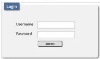
Login Username Password SubmitAfter connecting to the WebGUI's address in a web browser, the login screen will appear. Please enter the appropriate user name and password then click "Submit" to log in.
Note: The default user name and password is "admin".

text_image
Window Layout Picture Audio Input EDID HDCP Mode OSD Settings Logo Settings Ethernet Setup Information Logout Power OnOn the left side of the browser you will see the following menu tabs where all primary functions of the unit are controllable via the built in WebGUI. The individual functions will be introduced in the following sections.
Clicking the red "Logout" tab will automatically log the currently connected user out of the WebGUI and return to login page. Clicking on the "Power" button will toggle the unit's current power state between on (green) and stand-by (red).
UPPER TAB WINDOWS:
This upper section of the web interface is visible on every tab and provides control over the unit's operational mode, source selection, and output resolution as well as containing basic information about the currently connected source and display devices.
- Source: This section displays the currently detected resolution for the sources connected to each input.
2. Display:
- Resolution: Use the dropdown to select the preferred output resolution for the unit.
Note: Both outputs will always share the same output resolution, even in Matrix mode. - Sink A/B Native: Displays the native resolution of both connected displays as reported by their respective EDIDs.
3. Video Mode:
- Video Mode: Use the dropdown to select the unit's operational mode.
Available options are: Matrix, PiP, PoP, Quad, and Presets 1\~4.
Note: Switching between video modes will cause the output to briefly go to black, but audio output will not be affected if the selected audio source is the same in both modes.
- Win 1\~4: Select the video source to use in each window of a multiwindow mode (PiP/PoP/Quad/Preset).
Note: Only available when a multi-window mode is active.
- Out A\~B: Select the video source for each output in Matrix mode.
Note: Only available when Matrix mode is active.
WINDOW LAYOUT TAB:
This tab provides control over the position, size, aspect, priority, and other settings of each window in multi-viewer modes. A graphical representation of the layout is also provided. When the unit is in Matrix mode, only a limited selection of controls are available.
Note: Only the information from the currently selected window/input is displayed. A window's position and size cannot exceed the current output resolution.
- Selection: In multi-windowing modes, use the dropdown to select the window to modify. In Matrix mode select the input to modify.
Note: Changes made while a "Preset" video mode is selected will automatically be applied and saved to that preset.
- Display: Enable or disable the currently selected window.
Note: Not available in Matrix mode.
- Position X/Y: Set the X and Y coordinate position of the upper left corner of the currently selected window. Click on the "Save" button, after making changes, to make them active.
Note: Not available in Matrix mode.
- Size Width/Height: Set the horizontal and vertical size of the currently selected window. Click on the "Save" button, after making changes, to make them active.
Note: Not available in Matrix mode.
- Priority: Select the layer priority of the currently selected window. Priority 1 is at the front and priority 4 is at the back.
Note: Not available in Matrix mode.
- Aspect Ratio: Use the dropdown to select a fixed aspect ratio for the currently selected window or input. Available options are: Full, 16:9, 16:10, 4:3, Best Fit, and User. In multi-windowing modes the aspect ratio will be based on the window's current height. Selecting the "Full" aspect ratio will return the window to the current mode's default size and shape for that window. Selecting "Best Fit" will automatically set the ratio based on the window's current source resolution.
Note: The "User" aspect ratio is not available in Matrix mode.
-
Mirror: Turning this switch on will flip the currently selected window/input horizontally.
-
Border: This switch enables or disables the color border around the currently selected window or input.
-
Border Color: Use the dropdown to select the color to use for the border of the currently selected window/input. Available colors are: Black, red, green, blue, yellow, magenta, cyan, white, dark red, dark green, dark blue, dark yellow, dark magenta, dark cyan, gray.
-
Reset: Reset the current window/input to its default settings based on the currently selected mode.
-
Visual Layout Window: When in a multi-windowing mode, individual windows may be selected, moved and resized simply by clicking and dragging on them in the layout window. To select a window, click on it and the information will be displayed on the left. Click and drag the center of a window to reposition it. Click and drag the bottom right corner of a window to manually resize it. The results of a change will be displayed on the outputs as soon as the mouse button has been released.
Note: Not available in Matrix mode.
PICTURE TAB:
This tab provides controls over each input's contrast, brightness, saturation, hue, and sharpness levels.
Note: All picture settings are per-input and are mode-independent.
-
Input Select: Use the dropdown to select the input to modify.
-
Reset: Reset the current input to its default settings.
-
Contrast: This slider provides control over the overall contrast of the currently selected source video.
-
Brightness: This slider provides control over the overall brightness of the currently selected source video.
-
Saturation: This slider provides control over the overall saturation of the currently selected source video.
-
Hue: This slider provides control over the hue shift of the currently selected source video.
-
Sharpness H/V: These sliders provide control over the amount of sharpness processing to apply to the currently selected source video. Note: Horizontal and vertical processing is independently controlled, providing finer control over the image quality.
AUDIO TAB
This tab provides control over the audio output behavior of the unit, including routing selection and muting.
Note: Due to Matrix mode only supporting a single "window", changing modes between a multi-windowing mode and Matrix mode when an audio source is set to windows 2\~4 will result in the source reverting to window 1.
-
OUT A Source: Use the dropdown to choose the audio source to pair with video output A.
-
IN 1\~4: Always use the audio from the specified input.
• WIN 1\~4: Always use audio from the source currently displayed in the specified window.
Note: WIN 2\~4 is not available as a source in Matrix mode.
-
OUT B Source: Use the dropdown to choose the audio source to pair with video output A.
-
IN 1\~4: Always use the audio from the specified input.
- WIN 1\~4: Always use audio from the source currently displayed in the specified window.
Note: WIN 2\~4 is not available as a source in Matrix mode.
- OUT A Mute: Click the switch to toggle between muted and unmuted audio on output A.
- OUT B Mute: Click the switch to toggle between muted and unmuted audio on output A.
INPUT EDID TAB
This unit provides the option of three standard EDIDs, two sink sourced EDIDs and four user uploaded EDIDs that can be assigned to all inputs at the same time, or to each input independently.
Note: In most cases, assigning a new EDID to an input will cause the affected input to briefly blink out while the source adapts to the new information.
-
EDID Mode: Use the dropdown to select how to assign EDIDs to the unit's inputs. Selecting "Independent" allows for a different EDID to be assigned to each input, selecting "All" allows for a single EDID to be assigned to all inputs.
-
All EDID: Select the EDID to assign to all inputs.
Note: Only available in "All" EDID Mode.
- IN 1\~4 EDID: Select the EDID to assign to the specified input.
Note: Only available in "Independent" EDID Mode.
- User 1\~4 Update: To update any of the unit's 4 User EDIDs, click the "Choose File" button to open the file selection window and then select the EDID file (*.bin format) located on your local PC. After selecting the file, click the "Update" button to begin the EDID upload process.
Note: In some rare cases it is possible for custom or external EDIDs to cause compatibility issues with certain sources. If this happens, it is recommended to switch to one of the 3 default EDIDs for maximum compatibility.
HDCP MODE TAB
This tab provides control over the HDCP settings for all inputs.
-
HDCP Mode Input 1\~4: Use the dropdown to select the HDCP behavior for each input.
-
HDCP Support Off: Completely disables support for HDCP on that input.
- Refer to Source: Makes the input port support the same HDCP version as required by the connected source.
- Refer to Display: Makes the input support the HDCP version of the currently connected displays.
OSD SETTINGS TAB
This tab provides control over the behavior of the OSD menu and informational display.
- Menu Position: Use the dropdown to set the position of the OSD menu on the output. Available choices are: Top Left, Top Right, Bottom Right, and Bottom Left.
- Menu Timeout: Set the length of time, in seconds, that the OSD menu will continue to be displayed if there is no user input, or disable the timeout completely.
- Info. Timeout: Set the length of time, in seconds, that the informational OSD will be displayed after a signal or source change, or disable the timeout completely.
-
Info. Display: Enable or disable the informational OSD.
-
Menu Transparency: Set the transparency level of the background of the OSD menu with a range from Off (opaque) to 10 (mostly transparent).
- Menu background: Set the color of the background of the OSD menu. Available choices are: Gray, Black, and Blue.
LOGO SETTINGS TAB
This tab provides control over the user uploaded logo graphic. Controls include positioning, an uploading a new logo directly from the WebGUI and an option to reset the logo to a built in default image that can be used for testing.
-
Display: Enable or disable displaying the logo graphic.
-
Reset: Resets the logo and installs a default test image.
Note: The reset process can take a few moments. Progress information will be displayed on the OSD while the default logo is being installed. The
unit will automatically reboot when it is finished.
- Position X/Y: Sets the position of the logo's upper left corner, within the output. The position values are a relative percentage of the available output resolution.
- Logo Update: To upload a graphic logo, please click the "Choose File" button to open the file selection window and then select the graphic logo file (8-bit *.bmp format, 960x540 max resolution) located on your local PC. After selecting the file, click the "Update" button to upload the logo to the unit.
Note: The upload process can take a while, depending on the size of the logo. Progress information will be displayed on the OSD while the logo is being installed. The unit will automatically reboot when it is finished.
ETHERNET TAB
This tab provides controls to change the network settings for the unit. You can manually set the IP address, netmask and gateway address in "Static IP" mode, or you can obtain an IP address automatically by enabling DHCP.
Note: The unit's default Static IP address is 192.168.1.50. If the IP address is changed then the IP address required for WebGUI/Telnet access will also change accordingly.
- IP Mode: Click this button to toggle between the Static IP and DHCP modes. In DHCP mode, the unit will attempt to automatically obtain its IP configuration details from a local DHCP server. In Static mode the unit will use the manually assigned IP configuration information.
- Static IP Config: When the unit is in Static IP mode the IP address, netmask and gateway addresses may be manually set here. Click "Save" to apply and use the newly entered address.
- Link Status: Displays the unit's current IP configuration and the unit's MAC address.
SETUP TAB
Provides a way to update firmware and reset various sections within the unit. Control over the unit's Auto Sync Off feature, storing/recalling presets as well as configuring the WebGUI login settings is also provided here.
- Preset Save: Select a preset from the dropdown list and then click the "Save" button to store the unit's current video window configuration to the currently selected preset.
- Preset Recall: Select a preset from the dropdown list and then click the "Recall" button to activate the currently selected preset.
Note: this can also be achieved by selecting a Preset from the Video Mode dropdown at the top of the WebGUI.
- Auto Sync Off: Sets the amount of time to continue outputting sync with a black screen if there are no live sources and no operations have been executed on the unit. Setting this to "Always On" forces the unit to always output sync.
- Firmware Update: To update the unit's firmware, click the "Choose File" button to open the file selection window and then select the firmware update file (*.bin format) located on your local PC. After selecting the file, click the "Upgrade" button to begin the firmware update process. After the upgrade is complete, the unit will reboot automatically.
- User EDID Reset: Press this button to reset the unit's User EDIDs to their factory default states.
- Factory Reset: Press this button to reset the unit to its factory default state. After the reset is complete, the unit will reboot automatically.
- Web Login Settings: WebGUI login settings can be set here.
- Username/Password: To change the login username and password, enter the new information in the spaces provided and press "Save".
Note: The default user name and password is "admin".
- Timeout: Set the length of time to wait, in minutes, before logging out a user due to inactivity. Setting this to "0" disables the timeout. disables the timeout.
INFORMATION TAB
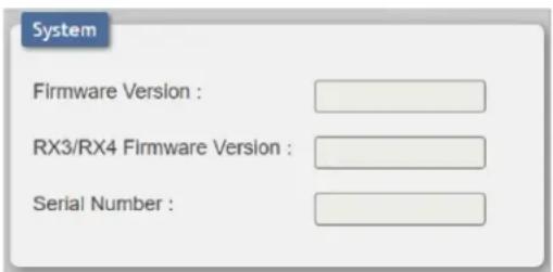
text_image
System Firmware Version : RX3/RX4 Firmware Version : Serial Number :This tab displays the unit's serial number as well as the current firmware versions.
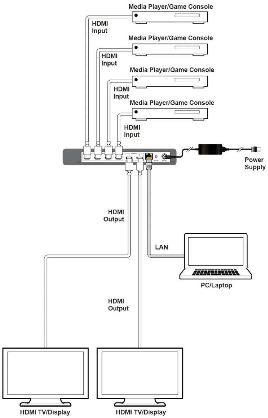
CONNECTION DIAGRAM
flowchart
graph TD
    A["HDMI TV/Display"] --> B["Media Player/Game Console"]
    A --> C["HDMI Input"]
    A --> D["HDMI Output"]
    A --> E["LAN"]
    A --> F["PC/Laptop"]
    G["HDMI TV/Display"] --> H["Media Player/Game Console"]
    G --> I["HDMI Input"]
    G --> J["HDMI Output"]
    G --> K["LAN"]
    G --> L["Power Supply"]
VIDEO SPECIFICATIONS
| SUPPORTED RESOLUTIONS (HZ) | INPUT OUTPUT | |
| HDMI HDMI | ||
| 720x400p@70/85 | √ | x |
| 640x480p@60/72/75/85 | √ | 60Hz |
| 720x480i@60 | √ | x |
| 720x480p@60 | √ | √ |
| 720x576i@50 | √ | x |
| 720x576p@50 | √ | √ |
| 800x600p@56/60/72/75/85 | √ | 60Hz |
| 848x480p@60 | √ | x |
| 1024x768p@60/70/75/85 | √ | 60Hz |
| 1152x864p@75 | √ | x |
| 1280x720p@50/60 | √ | √ |
| 1280x768p@60/75/85 | √ | 60Hz |
| 1280x800p@60/75/85 | √ | 60Hz |
| 1280x960p@60/85 | √ | 60Hz |
| 1280x1024p@60/75/85 | √ | 60Hz |
| 1360x768p@60 | √ √ | |
| 1366x768p@60 | √ | √ |
| 1400x1050p@60 | √ | √ |
| 1440x900p@60/75 | √ | 60Hz |
| 1600x900p@60RB | √ | √ |
| SUPPORTED RESOLUTIONS (HZ) | INPUT OUTPUT | |
| HDMI HDMI | ||
| 1600x1200p@60 | √ | √ |
| 1680x1050p@60 | √ | √ |
| 1920x1080i@50/60 | √ | x |
| 1920x1080p@24/25/30 | √ | √ |
| 1920x1080p@50/60 | √ | √ |
| 1920x1200p@60RB | √ | √ |
| 2560x1440p@60RB | √ | x |
| 2560x1600p@60RB | √ | x |
| 2048x1080p@24/25/30 | √ | x |
| 2048x1080p@50/60 | √ | x |
| 3840x2160p@24/25/30 | √ | √ |
| 3840x2160p@50/60 (4:2:0) | √ | x |
| 3840x2160p@24, HDR10 x x | ||
| 3840x2160p@50/60 (4:2:0), HDR10 x x | ||
| 3840x2160p@50/60 (4:4:4) | √ | √ |
| 4096x2160p@24/25/30 | √ | √ |
| 4096x2160p@50/60 (4:2:0) | √ | x |
| 4096x2160p@24, HDR10 x x | ||
| 4096x2160p@50/60 (4:2:0), HDR10 x x | ||
| 4096x2160p@50 (4:4:4) | √ | √ |
DIGITAL AUDIO
| HDMI INPUTS 1~2/ ALL OUTPUTS | |
| LPCM | |
| Max Channels 8 Channels | |
| Sampling Rate (KHz) 32, 44.1 | 48, 88.2, 96, 176.4, 192 |
| BITSTREAM | |
| Supported Formats Standard & High-Definition | |
| HDMI INPUTS 3~4 | |
| LPCM | |
| Max Channels 2 Channels | |
| Sampling Rate (KHz) 48 | |
| BITSTREAM | |
| Supported Formats None | |
PLEASE READ THE FOLLOWING TERMS AND CONDITIONS CAREFULLY BEFORE USING THIS HARDWARE, COMPONENTS AND SOFTWARE PROVIDED BY, THROUGH OR UNDER A-NeuVideo, INC (COLLECTIVELY, THE "PRODUCT"). By using installing or using the Product, you unconditionally signify your agreement to these Terms and Conditions. If you do not agree to these Terms and Conditions, do not use the Product and return the Product to A-NeuVideo, Inc. at the return address set forth on the Product's packing label at your expense. A-NeuVideo, Inc. may modify these Terms and Conditions at anytime, without notice to you.
RESTRICTIONS ON USE OF THE PRODUCT
It is your responsibility to read and understand the installation and operation instructions, both verbal and in writing, provided to you with respect to the Product. You are authorized to use the Product solely in connection with such instructions. Any use of the Product not in accordance with such instructions shall void any warranty pertaining to the Product. Any and all damages that may occur in the use of the Product that is not strictly in accordance with such instructions shall be borne by you and you agree to indemnify and hold harmless A-NeuVideo, Inc. from and against any such damage.
The Product is protected by certain intellectual property rights owned by or licensed to A-NeuVideo. Any intellectual property rights pertaining to the Product are licensed to you by A-NeuVideo, Inc. and/or its affiliates, including any manufacturers or distributors of the Product (collectively, "A-NeuVideo") for your personal use only, provided that you do not change or delete any proprietary notices that may be provided with respect to the Product.
The Product is sold to you and any use of any associated intellectual property is deemed to be licensed to you by A-NeuVideo for your personal use only. A-NeuVideo does not transfer either the title or the intellectual property rights to the Product and A-NeuVideo retains full and complete title to the intellectual property rights therein. All trademarks and logos are owned by A-NeuVideo or its licensors and providers of the Product, and you may not copy or use them in any manner without the prior written consent of A-NeuVideo, which consent may be withheld at the sole discretion of A-NeuVideo.
The functionality and usability of the Product is controlled by A-NeuVideo, Inc. from its offices within the State of Texas, United States of America. A-NeuVideo makes no representation that materials pertaining to the Product are appropriate or available for use in other locations other than the shipping address you provided with respect thereto. You are advised that the Product may be subject to U.S. export controls.
DISCLAIMERS AND LIMITATION OF LIABILITY
A-NeuVideo may change or modify the Product at any time, from time to time.
THE PRODUCT IS PROVIDED "AS IS" AND WITHOUT WARRANTIES OF ANY KIND EITHER EXPRESS OR IMPLIED. A-NEUVIDEO DOES NOT WARRANT OR MAKE ANY REPRESENTATIONS REGARDING THE USE OR THE RESULTS OF THE USE OF THE PRODUCT'S CORRECTNESS, ACCURACY, RELIABILITY, OR OTHERWISE.
A-NeuVideo has no duty or policy to update any information or statements pertaining to the Product and, therefore, such information or statements should not be relied upon as being current as of the date you use the Product. Moreover, any portion of the materials pertaining to the Product may include technical inaccuracies or typographical errors. Changes may be made from time to time without notice with respect to the Product.
TO THE FULLEST EXTENT PERMISSIBLE PURSUANT TO APPLICABLE LAW, A-NEUVIDEO DISCLAIMS ALL WARRANTIES, EXPRESS OR IMPLIED, INCLUDING, BUT NOT LIMITED TO IMPLIED WARRANTIES OF MERCHANTABILITY, FITNESS FOR A PARTICULAR PURPOSE AND NON-INFRINGEMENT. A-NEUVIDEO DOES NOT WARRANT THE ACCURACY, COMPLETENESS OR USEFULNESS OF ANY INFORMATION WITH RESPECT TO THE PRODUCT. A-NEUVIDEO DOES NOT WARRANT THAT THE FUNCTIONS PERTAINING TO THE PRODUCT WILL BE ERROR-FREE, THAT DEFECTS WITH RESPECT TO THE PRODUCT WILL BE CORRECTED, OR THAT THE MATERIALS PERTAINING THERETO ARE FREE OF DEFECTS OR OTHER HARMFUL COMPONENTS. A-NEUVIDEO WILL USE ITS REASONABLE EFFORTS TO CORRECT ANY DEFECTS IN THE PRODUCT UPON TIMELY WRITTEN NOTICE FROM YOU NOT TO EXCEED 10 BUSINESS DAYS AFTER RECEIPT BY YOU OF THE PRODUCT, BUT YOU (AND NOT A-NEUVIDEO) ASSUME THE ENTIRE COST OF ALL NECESSARY SERVICING, REPAIR AND CORRECTION THAT WAS CAUSED BY YOU UNLESS OTHERWISE AGREED TO IN A SEPARATE WRITING BY A-NEUVIDEO.
UNDER NO CIRCUMSTANCES, INCLUDING, BUT NOT LIMITED TO, NEGLIGENCE, SHALL A-NEUVIDEO BE LIABLE FOR ANY SPECIAL OR CONSEQUENTIAL DAMAGES THAT RESULT FROM THE USE OF, OR THE INABILITY TO USE THE PRODUCT IN ACCORDANCE WITH ITS SPECIFICATIONS, EVEN IF A-NEUVIDEO OR ITS REPRESENTATIVES HAVE BEEN ADVISED OF THE POSSIBILITY OF SUCH DAMAGES. IN NO EVENT SHALL A-NEUVIDEO'S TOTAL LIABILITY TO YOU FROM ALL DAMAGES, LOSSES, AND CAUSES OF ACTION (WHETHER IN CONTRACT, OR OTHERWISE) EXCEED THE AMOUNT YOU PAID TO A-NEUVIDEO, IF ANY, FOR THE PRODUCT.