
PowerCheck 1557 - Measurement Seaward - Free user manual and instructions
Find the device manual for free PowerCheck 1557 Seaward in PDF.


| Product Type | Portable Electrical Safety Tester |
| Brand | Seaward |
| Model | PowerCheck 1557 |
| Category | Measurement |
| Dimensions (approx.) | 150 x 70 x 30 mm |
| Weight (approx.) | 200 g (including battery) |
| Power Supply | 9V alkaline battery (PP3) |
| Display | LCD, 3½ digits, max reading 1999 |
| AC Voltage Range | 0 – 600 V |
| DC Voltage Range | 0 – 600 V |
| Resistance Range | 0 – 20 MΩ |
| Continuity Test | Yes, with audible beeper |
| Diode Test | Yes |
| Safety Rating | CAT III 600 V |
| Operating Temperature | 0°C to 40°C |
| Storage Temperature | -10°C to 50°C |
| Humidity | ≤ 80% RH (non-condensing) |
| Overload Protection | Fuse 500mA/250V |
| Maintenance | Clean with a dry lint-free cloth; do not use solvents. |
| Battery Replacement | When low battery indicator appears |
| Spare Parts / Repairability | No user-serviceable parts; contact Seaward service center. |
| Accessories Included | Test leads, battery, carry case, manual |
| Certifications | CE, UKCA |
Frequently Asked Questions - PowerCheck 1557 Seaward
User questions about PowerCheck 1557 Seaward
0 question about this device. Answer the ones you know or ask your own.
Ask a new question about this device
Download the instructions for your Measurement in PDF format for free! Find your manual PowerCheck 1557 - Seaward and take your electronic device back in hand. On this page are published all the documents necessary for the use of your device. PowerCheck 1557 by Seaward.
USER MANUAL PowerCheck 1557 Seaward
Operating Instructions

SEAWARD
Bracken Hill, South West Industrial Estate,
Peterlee, Co. Durham. SR8 2SW. England.
Tel: +44 (0)191 586 3511 Fax: +44 (0)191 586 0227
www.seaward.co.uk
sales@seaward.co.uk
service@seaward.co.uk
Limited Warranty & Limitation of Liability
SEAWARD Electronic Limited guarantees this product for a period of 1 year. The period of warranty will be effective at the day of delivery.
© Copyright 2008
All rights reserved. Nothing from this edition may be multiplied, or made public in any form or manner, either electronically, mechanically, by photocopying, recording, or in any manner, without prior written consent from SEAWARD Electronic Limited. This also applies to accompanying drawings and diagrams.
Due to a policy of continuous development SEAWARD Electronic Limited reserves the right to alter the equipment specification and description outlined in this publication without prior notice and no part of this publication shall be deemed to be part of any contract for the equipment unless specifically referred to as an inclusion within such contract.
Disposal of Old Product

natural_image
Symbol of a trash bin crossed with no text or numbers, representing waste sorting or disposal (no text present)This product has been designed and manufactured with high quality materials and components that can be recycled and reused.
When the crossed out wheelie bin symbol is attached to a product it means the product is covered by the European Directive 2002/96/EC.
Please familiarise yourself with the appropriate local separate collection system for electrical and electronic products.
Please dispose of this product according to local regulations. Do not dispose of this product along with normal waste material. The correct disposal of this product will help prevent potential negative consequences for the environment and human health.
Operating Instructions
PC1557 PAT and Installation Tester Checkbox
The PowerCheck 1557 is designed to be a full instrument verification system capable of testing all types of both installation testers and PAT testers.
The PowerCheck conforms with BSEN61010-1 and BSEN61326.
Contents
- User Notes
- Safety Notes
- Description
- Specifications
- General Overview
- PAT functionality
- Installation tester functionality
- Maintenance
- Cleaning
- Contact
1.0 User Notes
These operating instructions are intended for the use of competent personnel.
The PowerCheck 1557 has been designed for operation in a dry environment.
The following symbols are used in these operating instructions and on the PowerCheck 1557
Warning of electrical danger!
Indicates instructions must be followed to avoid danger to persons.
Important, follow the documentation!
This symbol indicates that the operating instructions must be adhered to in order to avoid danger.
2.0 Safety Notes
The PowerCheck 1557 has left the factory in a perfectly safe state. To maintain this state and ensure safe operation of the unit, all notes and warnings in these instructions must be observed at all times.

The PowerCheck 1557 is intended to prove
verification on a regular basis. It is not intended to replace annual calibration of the test equipment. It is also suggested that the PowerCheck is annually calibrated.

use test equipment which comply with IEC61010-1 and test leads which comply with IEC61010-031 with the PowerCheck 1557.

Using the PowerCheck 1557 in ways not described
by this manual may lead to damaging either the PowerCheck 1557 or the Measuring Device being checked.
3.0 Description
The PowerCheck 1557 is comprised of the following features:-
a) The ability to perform verification of PAT testers including;
i) 2 different earth bond values.
ii) 3 different insulation values
iii) 4 different flash test values
iv) 3 different PE current values
v) 3 different touch current values
b) The ability to perform verification of voltage measuring equipment.
c) The ability to perform verification of continuity measuring test equipment including;
i) 2 different continuity values
ii) to verify the voltage and current outputs meet the requirements of IEC1557
d) The ability to perform verification of insulation measuring test equipment including;
i) 3 different insulation values
ii) to verify the voltage and current outputs meet the requirements of IEC1557
e) The ability to perform verification of loop impedance measuring test equipment including;
i) 3 different loop impedance values
f) The ability to perform verification of RCD test equipment including;
i) No tripping of any series in-line RCD protection
ii) 3 different current ranges values
iii) 3 different test time values
iv) to verify the current outputs meet the requirements of IEC1557
4 Specifications
4.1 Environmental Specifications
The PowerCheck 1557 has been designed to be used in a dry environment.
Maximum barometric elevation for use is 2000M.
Overvoltage category IEC 60664/IEC 61010, 300V CAT II.
Pollution Degree 2 according IEC61010-1.
Protective system IP40 according to IEC 60529.
Electromagnetic compatibility (EMC) interference, immunity and emitted interference conforming to IEC 61326-1.
Operating temperature range 0^ C to 40^ C.
Storage temperature range -25°C to 65°C.
4.2 Mains Supply
Mains Supply Voltage 230V 10%
Mains Supply Frequency 50Hz 1Hz
4.3 PAT Electrical Test Specification
| Earth Bond | 0.2Ω, 2.0Ω | ±2% | ±20mΩ |
| Insulation | 0.5MΩ, 1MΩ, 2MΩ | ±2% | |
| PE Current | see reference table | ±2% | |
| Touch Current see reference table | ±2% | ||
| Flash | see reference table | ±2% |
| Mains | Supply | 210V | 220V | 230V | 240V | 250V | |
| Flash Test Type A (mA) | 0.5MΩ | 1.37 | 1.43 | 1.50 | 1.57 | 1.63 | |
| 1MΩ | 0.91 | 0.96 | 1.00 | 1.04 | 1.09 | ||
| 2MΩ | 0.55 | 0.57 | 0.60 | 0.63 | 0.65 | ||
| Flash Test Type B (mA) | 0.5MΩ | 2.74 | 2.87 | 3.00 | 3.13 | 3.26 | |
| 1MΩ | 1.37 | 1.43 | 1.50 | 1.57 | 1.63 | ||
| 2MΩ | 0.68 | 0.72 | 0.75 | 0.78 | 0.82 | ||
| PE / Touch Current (mA) | 0.5MΩ | 0.42 | 0.44 | 0.46 | 0.48 | 0.50 | |
| 1MΩ | 0.21 | 0.22 | 0.23 | 0.24 | 0.25 | ||
| 2MΩ | 0.11 | 0.11 | 0.12 | 0.12 | 0.13 |
FLASH TEST Type A are the values obtained for PAT test equipment which conform with EN50191. This includes the Supernova series of testers.
FLASH TEST Type B are the values obtained for PAT test equipment which do not conform with EN50191.
| Mains Supply | 210V 2 | 20V 230V | 240V | 250V | |
| FLASH CLII TEST | For verification of functionality only | ||||
4.4 Installation Electrical Test Specification
| Continuity | 0.5Ω, 2.0Ω ±2% ±20mΩ | |
| Continuity voltage | 4V < Un <24V | ±5% |
| Continuity current | In > 200mA 2R load | ±5% |
| Insulation | 0.25MΩ, 0.5MΩ, 1MΩ | ±2% |
| Insulation voltage | 250V, 500V, 1000V | ±5% |
| Insulation current | 0.1mA < In <15mA | ±5% |
| Voltage | mains input voltage | |
| Loop Impedance | 1Ω, 180Ω | ±5% |
| RCD test time | 30ms, 40ms, 250ms | ±3ms |
| RCD test current | 10mA, 30mA, 100mA | ±5% |
5 General Overview
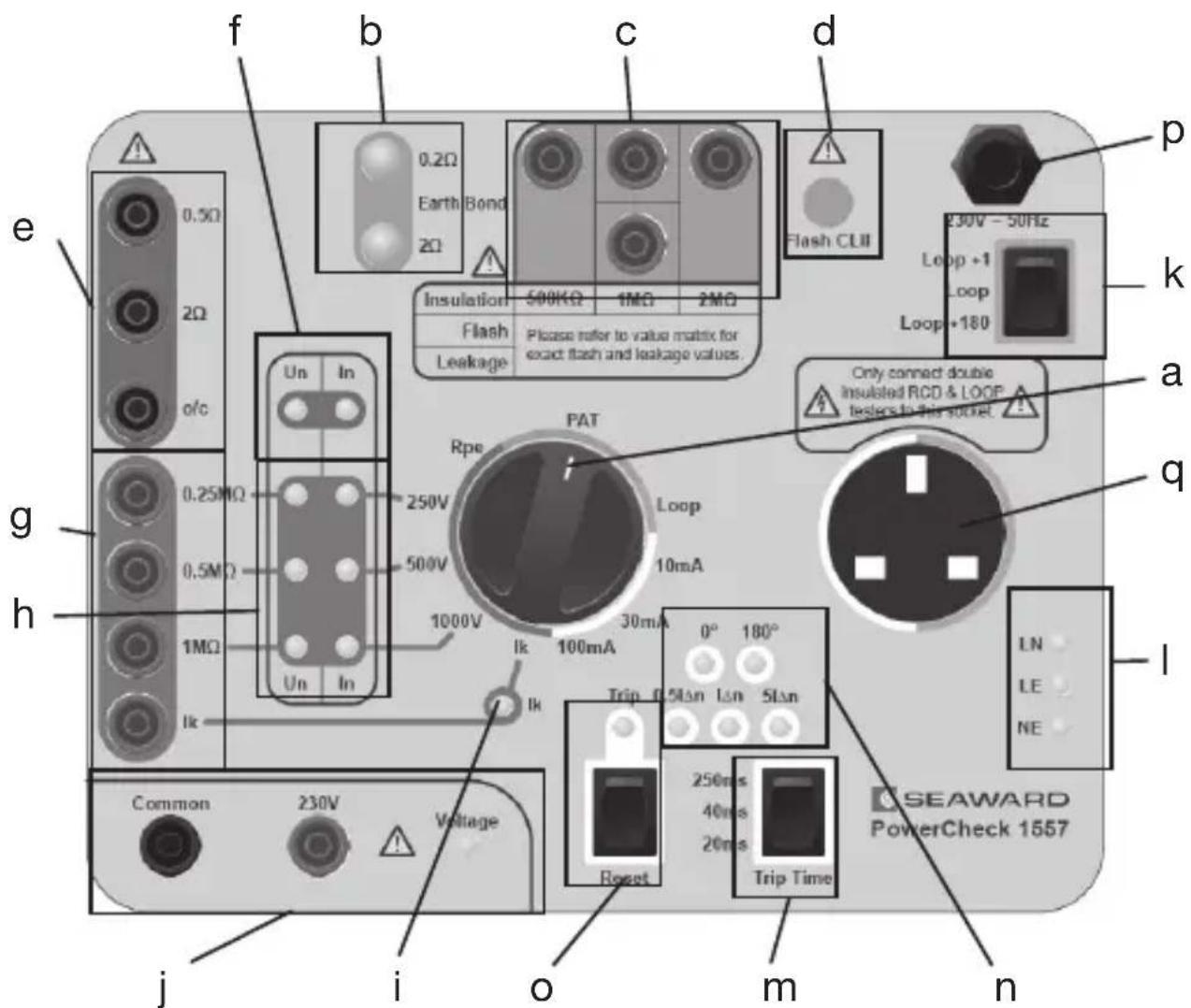
Figure 1: Front Panel
The PowerCheck 1557 comprises of the following elements;
5.1 General
a) Rotary switch which is used to select the required test functionality.
5.2 PAT Functionality
b) 2x Earth Bond test terminals.
c) 4x Insulation, PE/Touch Current and Flash test terminals which are used to obtain 3 different measurement values.
d) A Class II Flash test terminal.
5.3 Installation Tester Functionality
e) 2x Continuity measurement terminals and 1 voltage verification terminal.
f) Continuity voltage and current verification LEDs.
g) 3x Insulation measurement terminals and 1 current verification terminal.
h) Insulation voltage and current verification LEDs.
i) Insulation short current verification LED.
j) A voltage output and LED.
k) A Loop Impedance measurement selection switch.
I) Mains socket indication LEDs.
m) An RCD test time selection switch.
n) 5x RCD verification LEDs.
o) A reset LED and switch.
p) A mains power lead.
q) Loop/RCD mains outlet socket.
6.0 PAT Function Operation
6.1 Connections
Connect the PAT tester to a mains supply. Connect the PowerCheck 1557 mains plug into the EUT socket on the PAT tester. On the PowerCheck 1557 use the rotary switch to select the PAT function.
6.2 Earth Bond
The PowerCheck 1557 includes two Earth Bond test points, 0.2Ω and 2Ω. Connect one end of the earth bond probe to the PAT tester and clip the other end onto the appropriate resistance value stud. Perform an earth bond test. The PAT tester will indicate the test measurement taken.

Do not perform an Earth Bond test with >25A test setting.
The PowerCheck 1557 is protected by a thermal monitoring device. If the Earth Bond measurements start measuring open circuit after excessive testing then allow the PowerCheck 1557 to cool down before proceeding.
6.3 Insulation
The PowerCheck 1557 includes three Insulation test points, 0.5MΩ, 1.0MΩ and 2.0MΩ. These test points are selected by moving the link between the 4 red test terminals. See Figure2, Figure 3 and Figure 4.

Do not perform an Insulation test with >500Vdc test setting.

Figure 2: 500KΩ selected

Figure 3: 1MΩ selected

Figure 4: 2MΩ selected
Select the value required and perform an Insulation test. The PAT tester will indicate the test measurement taken.
6.4 Class I Flash Test
The PowerCheck 1557 includes three Class I Flash test currents, the value of this current is dependant on the mains voltage. The test point is selected by moving the link between the 4 red test terminals (see Figure 2, Figure 3 and Figure 4). The value selected is referenced to a table printed in the lid of the PowerCheck 1557. Select the test current required and perform a Flash test. The PAT tester will indicate the test measurement taken.

Do not perform a Flash test with >1500Vac test setting.
6.5 Class II Flash Test
The PowerCheck 1557 includes one Class II Flash test current, the value of this current is dependant on the mains voltage. Disconnect the black link which is used to select the Class I Flash test current value. Connect the Flash probe to the PAT tester and to the Flash CL II terminal on the front of the PowerCheck 1557 (see Figure 5). Perform a Flash test, the PAT tester will indicate the test measurement taken.

Do not perform a Flash test with >3000Vac test setting.

Figure 5: Flash CLII connection
6.6 PE Current Test
The PowerCheck 1557 includes three PE Current test currents, the value of these is dependant on the mains voltage. These test currents are selected by moving the link between the 4 red test terminals (see Figure 2, Figure 3 and Figure 4). The value selected is referenced to a table printed in the lid of the PowerCheck 1557. Select the test current required and perform a PE Current test. The PAT tester will indicate the test measurement taken.

Do not perform a PE Current Test if the mains voltage is outside of the ±10% specification.
6.7 Touch Current Test
The PowerCheck 1557 includes three Touch Current test currents, the value of these is dependant on the mains voltage. These test currents are selected by moving the PAT's touch current probe between 3 of the red test terminals (see Figure 6, Figure 7 and Figure 8). The value selected is referenced to a table printed in the lid of the PowerCheck 1557. Select the test current required and perform a Touch Current test. The PAT tester will indicate the test measurement taken.

Do not perform a Touch Current Test if the mains voltage is outside of the ±10% specification.

Figure 6: Touch Current value 1

Figure 7: Touch Current value 2

Figure 8: Touch Current value 3
7.0 Installation Function
7.1 Connections
Connect the PowerCheck 1557 Mains plug into a mains outlet socket.
7.2 Voltage
Connect the Installation tester between the Common and 230V test terminals, turn on the Installation tester and select Voltage. When the Voltage LED is illuminated 230Vac is present at the terminals, the Installation tester will measure this voltage. If the voltage goes off during testing unplug the PowerCheck 1557 from the mains supply and re-connect.

This voltage is dependant on the incoming mains supply. The Voltage will be present independent of the test type selected on the PowerCheck 1557.
7.3 Continuity
Select the Rpe function on the PowerCheck 1557, turn on the Installation tester and select the Continuity test.

not perform a Continuity test with >25A test setting.
7.3.1 Connect the Installation tester between the Common and the 0.5Ω terminals. Perform a Continuity test and ensure that the Installation tester measures within specification.
7.3.2 Connect the Installation tester between the Common and the 2.0Ω terminals. Perform a Continuity test and ensure that the Installation tester measures within specification. If the In LED indication is illuminated for the duration of the test then the Continuity test current meets the requirements of IEC1557.
7.3.3 Connect the Installation tester between the Common and the o/c terminals. Perform a Continuity test. If the Un LED indication is illuminated for the duration of the test then the Continuity test current meets the requirements of IEC1557.
7.4 Insulation
7.4.1 Select the 250V function on the PowerCheck 1557, turn on the Installation tester and select the Insulation test. Setup the Installation tester to output 250V. Connect the Installation tester between the Common and 0.25MΩ terminals. Perform an Insulation test and ensure that the Installation tester measures within specification. Ensure that both the Un and In LEDs are illuminated, this indicates that the Insulation voltage and current meet the requirements of IEC1557.
7.4.2 Connect the Installation tester between the Common and 0.5MΩ terminals. Perform an Insulation test and ensure that the Installation tester measures within specification.
7.4.3 Connect the Installation tester between the Common and 1.0MΩ terminals. Perform an Insulation test and ensure that the Installation tester measures within specification.
7.4.4 Select the 500V function on the PowerCheck 1557, turn on the Installation tester and select the Insulation test. Setup the Installation tester to output 500V. Connect the Installation tester between the Common and 0.5MΩ terminals. Perform an Insulation test and ensure that the Installation tester measures within specification. Ensure that both the Un and In LEDs are illuminated.
7.4.5 Connect the Installation tester between the Common and 0.25MΩ terminals. Perform an Insulation test and ensure that the Installation tester measures within specification.
7.4.6 Connect the Installation tester between the Common and 1.0MΩ terminals. Perform an Insulation test and ensure that the Installation tester measures within specification.
7.4.7 Select the 1000V function on the PowerCheck 1557, turn on the Installation tester and select the Insulation test. Setup the Installation tester to output 1000V. Connect the Installation tester between the Common and 1.0MΩ terminals. Perform an Insulation test and ensure that the Installation tester measures within
specification. Ensure that both the Un and In LEDs are illuminated.
7.4.8 Connect the Installation tester between the Common and 0.25MΩ terminals. Perform an Insulation test and ensure that the Installation tester measures within specification.
7.4.9 Connect the Installation tester across the Common and 0.5MΩ terminals. Perform an Insulation test and ensure that the Installation tester measures with specification.
7.4.10 Select the Ik function on the PowerCheck 1557, turn on the Installation tester and select the Insulation test. Setup the Installation tester to output 250V. Connect the Installation tester between the Common and Ik terminals. Perform an Insulation test and ensure that the Ik LED is illuminated.
7.4.11 Select the Ik function on the PowerCheck 1557, turn on the Installation tester and select the Insulation test. Setup the Installation tester to output 500V. Connect the Installation tester between the Common and Ik terminals. Perform an Insulation test and ensure that the Ik LED is illuminated.
7.4.12 Select the Ik function on the PowerCheck 1557, turn on the Installation tester and select the Insulation test. Setup the Installation tester to output 1000V. Connect the Installation tester between the Common and Ik
terminals. Perform an Insulation test and ensure that the Ik LED is illuminated.
7.5 Loop Impedance
Plug the PowerCheck 1557 into a wall mains socket. Select the Loop function on the PowerCheck 1557.
If the LN and LE LEDs are not illuminated then the mains supply does meet the requirements in order to perform Loop tests, testing is inhibited.
Connect the Installation tester to the mains outlet socket on the front of the PowerCheck 1557, turn on the Installation tester and select the Loop Impedance test.
Do not perform a Loop Impedance test with >25A test setting.
7.5.1 Ensure that the Loop Impedance rocker switch is in the Loop position, perform a Loop test and note the value.
7.5.2 Switch the Loop Impedance rocker switch to the Loop+1 position. Perform a Loop test. Ensure that the Installation measures 1 more than the measurement obtained in 7.5.1. Ensure the measurement is within specification.
7.5.3 Switch the Loop Impedance rocker switch to the Loop+180 position. Perform a Loop test. Ensure that the
Installation measures 180Ω more than the measurement obtained in 7.5.1. Ensure the measurement is within specification.
7.6 RCD
Plug the PowerCheck 1557 into a wall mains socket. Select the 10mA RCD test current on the PowerCheck 1557.
If the LN and LE LEDs are not illuminated then the mains supply does meet the requirements in order to perform Loop tests, testing is inhibited.
Connect the Installation tester to the mains outlet socket on the front of the PowerCheck 1557, turn on the Installation tester and select the RCD test.
7.6.1 Setup the Installation tester so that it will test 0° 0.5lΔn using the same test current that has been selected on the PowerCheck 1557. Perform an RCD test. The 0° and 0.5lΔn LED will be illuminated. The simulated RCD will not trip for 0.5lΔn tests.
7.6.2 Setup the Installation tester so that it will test 180° 0.5lΔn using the same test current that has been selected on the PowerCheck 1557. Perform an RCD test. The 180° and 0.5lΔn LED will be illuminated. The simulated RCD will not trip for 0.5lΔn tests.
7.6.3 Setup the Installation tester so that it will test 0° IΔn using the same test current that has been selected on the PowerCheck 1557. Select a trip time on the PowerCheck 1557. Perform an RCD test. The 0° and IΔn LED will be illuminated. The simulated RCD will trip as indicated by the illuminated Trip LED. The Installation tester will measure the test time selected on the PowerCheck 1557. In order to reset the simulated RCD press the Reset switch, the Trip LED will go off.
7.6.4 Setup the Installation tester so that it will test 180° IΔn using the same test current that has been selected on the PowerCheck 1557. Select a trip time on the PowerCheck 1557. Perform an RCD test. The 180° and IΔn LED will be illuminated. The simulated RCD will trip as indicated by the illuminated Trip LED. The Installation tester will measure the test time selected on the PowerCheck 1557. In order to reset the simulated RCD press the Reset switch, the Trip LED will go off.
7.6.5 Setup the Installation tester so that it will test 0° 5lΔn using the same test current that has been selected on the PowerCheck 1557. Select a trip time on the PowerCheck 1557. Perform an RCD test. The 0° and 5lΔn LED will be illuminated. The simulated RCD will trip as indicated by the illuminated Trip LED. The Installation tester will measure the test time selected on the PowerCheck 1557. In order to reset the simulated RCD press the Reset switch, the Trip LED will go off.
7.6.6 Setup the Installation tester so that it will test 180° 5lΔn using the same test current that has been selected on the PowerCheck 1557. Select a trip time on the PowerCheck 1557. Perform an RCD test. The 180° and 5lΔn LED will be illuminated. The simulated RCD will trip as indicated by the illuminated Trip LED. The Installation tester will measure the test time selected on the PowerCheck 1557. In order to reset the simulated RCD press the Reset switch, the Trip LED will go off.
7.6.7 Repeat steps 7.6.1 to 7.6.6 for the 30mA and 100mA test ranges.
8.0 Maintenance
8.1 The PowerCheck 1557 is extremely robust and should always be kept free from dust.
8.2 Ensure the PowerCheck 1557 is kept dry with no surface moisture on the unit.
8.3 The case of the PowerCheck 1557 should be regularly inspected to ensure no physical damage.
8.4 Ensure the insulation of the power cable is fully intact and that no sharp creases have occurred in the cable.
8.5 If any of the above conditions have been observed then the PowerCheck 1557 must be appropriately secured to prevent any further use.
9.0 Cleaning
9.1 Clean the external case and front panel of the PowerCheck 1557 with a clean dry cloth.
10.0 Contact
For help or advice contact:
Tel: 0191 5878718
For Service and Calibration contact:
Service Department
Seaward Electronic
Bracken Hill
South West Industrial Estate
Peterlee
Co Durham SR8 2SW
England
Tel: 0191 5878739 / 0191 5878737
Email: service@seaward.co.uk
369A552 Rev 4


- Operating Instructions
- SEAWARD
- Limited Warranty & Limitation of Liability
- Disposal of Old Product
- PC1557 PAT and Installation Tester Checkbox
- Contents
- User Notes
- Safety Notes
- Description
- Specifications
- Environmental Specifications
- Mains Supply
- General Overview
- General
- PAT Functionality
- Installation Tester Functionality
- PAT Function Operation
- Connections
- Earth Bond
- Insulation
- Class I Flash Test
- Class II Flash Test
- PE Current Test
- Touch Current Test
- Installation Function
- Connections
- Voltage
- Continuity
- Insulation
- Loop Impedance
- RCD
- If the LN and LE LEDs are not illuminated then the mains supply does meet the requirements in order to perform Loop tests, testing is inhibited.
- Maintenance
- Cleaning
- Contact
Brand : Seaward
Model : PowerCheck 1557
Category : Measurement