
0070-08112 - Security Camera Ernitec - Free user manual and instructions
Find the device manual for free 0070-08112 Ernitec in PDF.


| Product Type | Eyeball Network Camera |
| Brand | Ernitec |
| Model | 0070-08112 |
| Power Supply | DC 12V / PoE (IEEE 802.3af) |
| Network Interface | 10/100Mbps Ethernet with PoE |
| Video Output | CVBS analog video (1 channel) |
| Audio | Audio input and output (on supported models) |
| Alarm Interface | Alarm input/output (on supported models) |
| Storage | Micro SD card slot (up to 128GB) |
| Fill Light Modes | Intelligent dual, warm, infrared, off |
| Night Vision | Yes (infrared and warm light) |
| Adjustable Angle | Pan: 0-360°, Tilt: 0-80°, Rotation: 0-360° |
| Mounting Type | Ceiling or wall mount (with included accessories) |
| Intelligent Analysis | Perimeter, virtual fence, loitering, converse, personnel count |
| AI Multi-object Detection | Face, full body, vehicle detection |
| Personnel Counting | Yes (query by year, month, day; chart and list) |
| Reset Button | Long press 5 seconds to restore default settings |
| Cleaning | Soft dry cloth; use neutral cleanser for stubborn dirt |
| Operating Environment | Indoor/Outdoor (with insect and moisture protection) |
| Safety Compliance | LPS standard power adapter required; local electrical safety standards |
| Included Accessories | Quick Setup Guide, accessory package, location sticker |
Frequently Asked Questions - 0070-08112 Ernitec
User questions about 0070-08112 Ernitec
0 question about this device. Answer the ones you know or ask your own.
Ask a new question about this device
Download the instructions for your Security Camera in PDF format for free! Find your manual 0070-08112 - Ernitec and take your electronic device back in hand. On this page are published all the documents necessary for the use of your device. 0070-08112 by Ernitec.
USER MANUAL 0070-08112 Ernitec
Precautions
Fully understand this document before using this device, and strictly observe rules in this document when using this device. If you install this device in public places, provide the tip "You have entered the area of electronic surveillance" in an eye-catching place. Failure to correctly use electrical products may cause fire and severe injuries.
| WARNING | It alerts you to moderate dangers which, if not avoided, may cause minor or moderate injuries. |
| CAUTION | It alerts you to risks. Neglect of these risks may cause device damage, data loss, device performance deterioration, or unpredictable results. |
| NOTE | It provides additional information. |
WARNING
Strictly observe installation requirements when installing the device. The manufacturer shall not be held responsible for device damage caused by users' non-conformance to these requirements.
Strictly conform to local electrical safety standards and use power adapters that are marked with the LPS standard when installing and using this device. Otherwise, this device may be damaged.
Use accessories delivered with this device. The voltage must meet input voltage requirements for this device.
If this device is installed in places with unsteady voltage, ground this device to discharge high energy such as electrical surges in order to prevent the power supply from burning out. When this device is in use, ensure that no water or any liquid flows into the device. If water or liquid unexpectedly flows into the device, immediately power off the device and disconnect all cables (such as power cables and network cables) from this device.
Do not focus strong light (such as lighted bulbs or sunlight) on
this device. Otherwise, the service life of the image sensor may be shortened.
- If this device is installed in places where thunder and lightning frequently occur, ground the device nearby to discharge high energy such as thunder strikes in order to prevent device damage.
CAUTION
- Avoid heavy loads, intensive shakes, and soaking to prevent damages during transportation and storage. The warranty does not cover any device damage that is caused during secondary packaging and transportation after the original packaging is taken apart.
- Protect this device from fall-down and intensive strikes, keep the device away from magnetic field interference, and do not install the device in places with shaking surfaces or under shocks.
- Clean the device with a soft dry cloth. For stubborn dirt, dip the cloth into slight neutral cleanser, gently wipe the dirt with the cloth, and then dry the device.
- Do not jam the ventilation opening. Follow the installation instructions provided in this document when installing the device.
- Keep the device away from heat sources such as radiators, electric hangers, or other heat equipment.
- Keep the device away from moist, dusty, extremely hot or cold places, or places with strong electric radiation.
- If the device is installed outdoors, take insect- and moisture-proof measures to avoid circuit board corrosion that can affect monitoring.
- Remove the power plug if the device is idle for a long time.
- Before unpacking, check whether the fragile sticker is damaged. If the fragile sticker is damaged, contact customer services or sales personnel. The manufacturer shall not be held responsible for any artificial damage of the fragile sticker.
Special Announcement
- All complete products sold by the manufacturer are delivered along with nameplates, quick setup guide and accessories after strict inspection. The manufacturer shall not be held responsible for counterfeit products.
- The manufacturer will update this manual according to product function enhancement or changes and regularly update the software and hardware described in this manual. Update information will be added to new versions of this manual without prior notice.
- This manual may contain misprints, technology information that is not accurate enough, or product function and operation description that is slightly inconsistent with the actual product, the final interpretation of company is as a standard.
- This manual is only for reference and does not ensure that the information is totally consistent with the actual product. For consistency, see the actual product.
NOTE
For more information, please refer to website.
1 Open Package Examination
Open the package, check the appearance of product for no obvious damage, and confirm the item list for table 1-1 is consistent.
Table 1-1 Packing list
| Component | Quantity | Remark |
| Eyeball Network Camera | 1 | |
| Quick Setup Guide | 1 | |
| Accessory package | 1 | |
| Location sticker | 1 |
2 Device Structure
2.1 Device Ports
NOTE
Different devices may have different interfaces, multi-head cables, and fill lights; Please refer to the actual product.
Figure 2-1 Hardware interfaces

Table 2-1 Hardware interfaces description
| ID | Port Name | Description |
| 1 | SD card slot | Install a SD card. ⚪NOTEBefore installing a SD card, make sure the card not in write protection state.Before removing the SD card, make sure the card not in write protection state.Otherwise, the data may be lost,or the SD card may be damaged. |
| 2 | CVBS video out | Output an analog video signal. You can connect the camera to a TV monitor through this interface to view the analog video. |
| 3 | Reset button | Long press the reset button for 5 seconds to restore the original settings. |
Fill light settings
Camera's fill light has four modes, they are intelligent dual light (current fill light will switch to warm light after an alarm is triggered, and will switch back to the original fill light for 30s after the alert is released.), warm light, infrared lamp and none (Close the fill light and the color of image will stay in previous mode).
The different cameras can be set different fill light modes, please set fill light modes according to the actual scene.
Day mode: It can be used in the scene with sufficient ambient light for 24 hours, do not turn on the fill light, and the image is in color. Night mode: it can be used in the scene where there is insufficient ambient light for 24 hours, turn on the fill light (it can be selected according to the four modes of the fill light).
Auto mode: Automatically switch the fill light mode according to the luminance of the environment.
Timing mode: Set the start and end time of the day, this time period is day mode for camera.
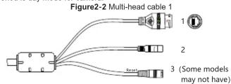
Table 2-2 Multi-head cable description
| ID | Core | Description | Remark |
| 1 | Network access interface | Connects to a standard Ethernet cable or PoE. The green light is on, the network connection is normal; The yellow light flashes when the data is transmitted. Some models maybe not have the lights; Please refer to the actual product. | Support PoE supply. |
| 2 | Power supply (DC 12V) | Connects to a 12V direct current (DC) power supply. | |
| 3 | Reset button | Long press the reset button for 5s to restore the original settings. |

| ID | Core | Description | Remark |
| 1 | Network access interface | Connect to a standard Ethernet cable or PoE. The green light is on, the network connection is normal; The yellow light flashes when the data is transmitted. Some models maybe not have the lights; Please refer to the actual product. | Support PoE supply. |
| 2 | Audio output | Connect to an external audio device such as a speaker. | Applied for camera with audio function |
| 3 | Audio input port | Receive an analog audio signal from devices such as a sound pickup device. | |
| 4 | Power supply (DC 12V) | Connect to a 12V direct current (DC) power supply. | |
| 5 | Reset button | Long press the reset button for 5s to restore the original settings. | Applied for some models |
| 6 | G | Alarm output COM | Applied for alarm function |
| OUT | Alarm output | ||
| G | Alarm input COM | ||
| IN | Alarm input |
2.2 Camera Dimensions
NOTE
Different devices may have different dimensions; Please refer to the actual product.
Figure 2-4 Dimensions Unit: mm

Device Installation
Installation Steps:
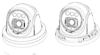
Step 1 Open the package, take out the camera, and disassemble camera's decorate cover, as shown in figure 3-1.
Figure 3-1 Disassemble camera
natural_image
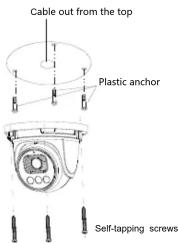
Technical line drawing of two identical mechanical components with circular features and mounting brackets (no text or symbols)Step 2 Stick the installation location sticker on the ceiling or wall, drill three holes following the marks on the sticker. Push the plastic anchors into he holes, as shown in figure 3-2.
Step 3 Correspond the camera to plastic anchors, fix it to the ceiling (or wall) by using self-tapping screws.
Figure 3-2 Camera installation
NOTE
You can route cables from the top or from the side. If you use the top routing method, drill a hole in the installation surface first, as shown in figure 3-2, If you use the side routing method, please cut the compression ring outlet, and route the multi-head cable out from the side gap at the bottom of the camera.
Step 4 Connected the multi-connector cable, the camera is connected to screen to adjust monitoring perspective, then tighten the decorate cover, as shown in figure 3-3.
Figure 3-3 Finish installation

NOTE
The camera's monitoring angle can be adjusted by three-axis rotation: horizontal rotation, up and down rotation, axial rotation of the lens, adjust the direction of the camera and aim the lens at the target.
1 The hemisphere can rotate up and down range of 0 to 80^ ;
2 the hemisphere can rotate left and right range of 0 to 360^ ;
3 The ball lining can rotate 360^ left and right.
Quick Configuration(e.g IE)
4.1 Login
Step 1 Open the Internet Explorer, enter the IP address of IP camera (default value: 192.168.0.120 in the address box, and press Enter. The login page is displayed as shown in figure 4-1. Step 2 Input the user name and password.
NOTE
- The default user name is admin. The default password is admin. Modify the password when user logs into the system for first time to ensure system security. - It is advised to restart the device three minutes later after modifying password to ensure modified successfully
• You can change the system display language on the login page.
Figure 4-1 Login

Step3 Click Login, the main page is displayed.
4.2 Modify IP address
Choose Configuration > Device > Local Network, the Local Network page is displayed.
Enter the IP address in the IP Address box and click Apply as shown in figure 4-2.
After the success of the IP address setting, please use the new IP address to log in the Web interface.
Figure 4-2 Local Network
Local Network

4.3 Browsing Video
To ensure the real-time video can be played properly, you must perform the following operation when you log in the web for the first time: If user can access the web immediately, please ignore the steps of adding trusted sites.
Step 1 the Internet Explorer. Choose Tools > Internet options > Security > Trusted sites > Sites, in the display dialog box, click Add, as shown in figure 4-3.
Figure 4-3 Adding a trusted site

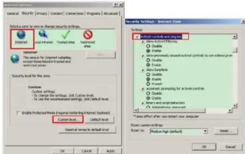
Step 2 In the Internet Explorer, choose Tool > Internet Options > Security > Customer level and set Download unsigned ActiveX control and initialize and script ActiveX controls not marked as safe for scripting under ActiveX controls and plug-ins to Enable, as shown in figure 4-4.
Figure 4-4 Configuring ActiveX control and plug-in
Step 3 Download and install the player control as prompted.
NOTE
If the repair tips displayed when installing the control, please ignore the prompt, and continue the installation, the login page is displayed when the control is loaded.
To browse a real-time video, click Live Video. The Live Video page is displayed, as shown in figure 4-5.
Figure 4-5 Live Video

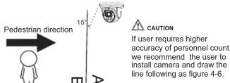
1 Personnel Count: User can query the data of personnel count, through year, month, day. The statistics can be downloaded. The data can be shown by line chart, histogram, list.
2 AI Live video: Click the icon to view the snapshots of human face or license plate (click "Face" or "Plate" to switch). The bottom page will show the captured images of vehicle and human face.
Figure 4-6 Installation of personnel count
4.4 Intelligent Analysis
At "Configuration > Intelligent Analysis" interface, user can set the parameters of Perimeter, Single Virtual Fence, Double Virtual Fence, Multi Loiter, Converse and Personnel Count, as shown in figure 4-7.
Figure 4-7 Intelligent Analysis

4.5 AI Multi object
At "Configuration > AI Multi object" interface, user can enable face detection, full body detection, vehicle detection, set the other parameters of detection, as shown in figure 4-8.
Figure 4-8 AI Multi-object

NOTE
For better capture performance, it is recommended to use 6mm focus length lens or above.
Brand : Ernitec
Model : 0070-08112
Category : Security Camera