MAC-12000 - Heating Ravanson - Free user manual and instructions
Find the device manual for free MAC-12000 Ravanson in PDF.


| Product Type | Fan Heater |
| Brand | Ravanson |
| Model | MAC-12000 |
| Dimensions (W x D x H) | 20 x 15 x 30 cm |
| Weight | 1.5 kg |
| Power Supply | 220-240 V ~ 50/60 Hz |
| Power Consumption | 2000 W |
| Heating Element | Ceramic PTC |
| Number of Heat Settings | 2 (1000 W / 2000 W) |
| Fan Modes | Cool Air Only, Warm Air |
| Thermostat | Adjustable Thermostat |
| Oscillation | Yes, 70° |
| Safety Features | Overheat Protection, Tip-Over Switch |
| Housing Material | High-Grade Plastic |
| Control Type | Rotary Knobs |
| Noise Level | 45 dB |
| Room Coverage | Up to 25 m² |
| Maintenance | Clean air intake grille regularly with a vacuum |
| Spare Parts Available | Replacement filter, fan motor (service center) |
| Repairability Index | Moderate |
| Included Accessories | User Manual |
Frequently Asked Questions - MAC-12000 Ravanson
User questions about MAC-12000 Ravanson
0 question about this device. Answer the ones you know or ask your own.
Ask a new question about this device
Download the instructions for your Heating in PDF format for free! Find your manual MAC-12000 - Ravanson and take your electronic device back in hand. On this page are published all the documents necessary for the use of your device. MAC-12000 by Ravanson.
USER MANUAL MAC-12000 Ravanson
ENG User's manual Local Air Conditioner
natural_image
Line drawing of a portable air conditioner unit with control panel and ventilation slots (no text or symbols)MODEL:
MAC-12000; MAC-9000
Producent/Manufacturer/Tillverkare/Produsenten:
Ravanson®
RAVANSON LTD Sp. z o.o.
natural_image
Line drawing of a portable air conditioner unit with wheels and a handle (no text or symbols)Przód
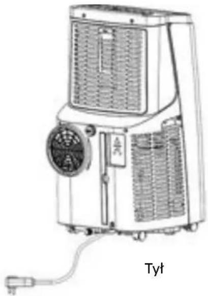
natural_image
Line drawing of a portable air heater unit with cooling fan and ventilation slots (no text or symbols)natural_image
Pure structural diagram of a truss or beam with diagonal bracing (no text or symbols)1

natural_image
Simple line drawing of a rectangular shape with an oval cutout on the left side (no text or symbols)2
USTAWIENIE
natural_image
Three technical diagrams showing vertical cylindrical components with labeled sections A and B, and a separate 3D view of a mechanical component (no text or symbols present)natural_image
Pure diagram of a door with double-headed arrows indicating direction, no text or symbols present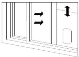
natural_image
Diagram showing two arrows pointing to a window with a vertical arrow and a horizontal arrow, no text or symbols present.natural_image
Line drawing of a portable air conditioner unit with a hand inserting a hose (no text or symbols)natural_image
Line drawing of a portable air conditioner unit connected to a door (no text or symbols)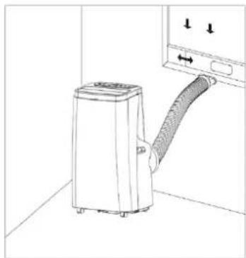
natural_image
Line drawing of a portable air conditioner unit with a coiled hose, mounted on a wall (no text or symbols)natural_image
Line drawing of an air conditioner unit with fan and cooling fan (no text or symbols)natural_image
Line drawing of an air conditioner unit with a cup pouring liquid from the side arm (no text or symbols)natural_image
Technical line drawing of a portable air conditioner unit with fan and vent (no text or symbols)Ostrzeżenie!!!
When you use electric devices, comply with the basic precautions to reduce the risk of fire, electric shock and/or personal injuries.
Be sure to carefully review this manual before using the product for the first time and keep it at hand for future reference.
Before first use, always read the safety instructions and warnings included in this guide.
Failure to observe the below mentioned safety warnings and safety guidelines for may cause to electric shock, fire and/or serious injuries Keep safety instructions and warnings at hand for future reference GENERAL SAFETY GUIDELINESS
This appliance is not intended for use by children under the age of 8 or other persons, without assistance or supervision, if their physical, sensory or mental capabilities prevent them from using it safely or by persons without experience and knowledge on the use thereof. People using this product must understand the risks related to the use of the appliance. Do not allow children to use the appliance as a toy. Cleaning and maintenance by children without supervision is not allowed.
Children are not aware of dangers that may arise during the use of electric devices. Keep the appliance and corresponding cord out of the reach of children under the age of 8.
Children should be supervised to ensure that they do not play with the appliance.
WARNING! Do not operate the appliance with a damaged cord.
Damaged power cord must be replaced by manufacturer, authorized service centre or other qualified persons in order to avoid risk.
Do not allow the power cord to touch sharp edges or hot surfaces.
Damaged cord poses a risk of electric shock
The plug must fit the socket.
The plug must not be modified in any way.
It is recommended to connect the device to the power supply network equipped with a residual current device (RCD) with a switch-off current of 30mA or less.
Installation must comply with the regulations in force in the country where the device is used. If you have any doubts concerning the electrical system, ask a qualified electrician.
The device must be placed so as the access to the electrical socket is not obstructed.
Do not use any extension cord for the air-conditioner unless it has been inspected and tested by a qualified electrician or electrical part supplier.
Do not use outside. Do not expose to rain. Protect against humidity. Do not operate with wet hands.
Do not operate with wet hands. Prevent water from spilling onto the unit.
Do not leave the unit running unattended.
Do not tilt or turn over the unit.
Do not unplug while the unit is operating
Do not use an extension cord or an adapter plug.
Do not put objects on the unit.
Do not climb or sit on the unit.
Do not insert fingers or other objects into the air outlet.
Do not touch the air inlet or the aluminium fins of the unit.
Do not operate the unit if it is dropped, damaged or showing signs of product malfunction.
Use only a soft damp (not wet) cloth with mild detergent to clean the appliance. Do not use solvents, petrol or other measures that would damage the device.
Transport in an original packaging that protects against mechanical damages.
The appliance must be repaired only by a qualified person and with the use of original spare parts.
WARNING! Ventilation openings in the device housi adjacent partitions must be perfectly patent and free from any obstacles.
WARNING! Do not put any objects through the device openings.
WARNING! Do not damage the cooling circuit.
WARNING! Do not use electric devices inside chambers designated for food storage, unless they are the type recommended by the manufacturer.
Before dismounting, assembly or cleaning the air-conditioner, unplug it.
The air-conditioner must always be stored and transported in the upright position as otherwise the compressor can be damaged permanently.
Place the air-conditioner in the destination place and wait 24 h before switching it on.
Avoid restarting the air-conditioner less than 4 minutes after switching it off as the compressor may be damaged otherwise.
Do not use the plug to switch the air-conditioner on and off. Always use the ON/OFF switch on the control panel.
Despite operating the unit in accordance with its intended use and in accordance with all safety guidelines, it is impossible to eliminate all residual risk factors.
PLEASE NOTE!
Any service maintenance other than regular filter cleaning or replacements should be carried out by the authorized repair team.
The failure to comply with this requirement can render your guarantee void.
WARNING!
The air-conditioner contains eco-friendly natural gas propane R290. Before switching the device on, ensure the cooling circuit has not been damaged. A direct contact with evaporating R290 medium can lead to skin frostbiting and eye irritation.

Appliance shall be installed, operated and stored in a room with a floor area larger than 10 m^2
Keep any required ventilation openings clear of obstruction;
Servicing shall be performed only as recommended by the manufacturer.
The appliance shall be stored in a well-ventilated area where the room size corresponds to the room area as specified for operation.
Any person who is involved with working on or breaking into a refrigerant circuit should hold a current valid certificate from an industry-accredited assessment authority, which authorizes their competence to handle refrigerants safely in accordance with an industry recognized assessment specification.
If a leak is detected, immediately evacuate all persons from the store, ventilate the room and contact the local fire department to advise them that a propane leak has occurred.
Symbols

This unit uses a flammable refrigerant.

Read the USER MANUAL carefully before operation.

Further information is available in the USER MANUAL, SERVICE MANUAL

Service personnel are required to carefully read the USER MANUAL and SERVICE MANUAL before operation
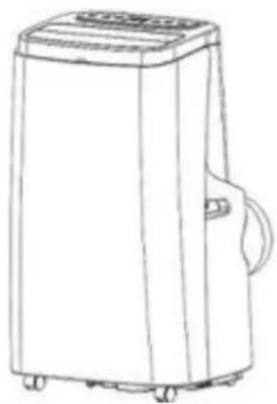
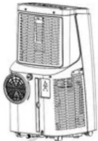
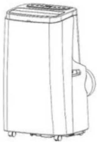
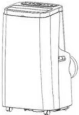
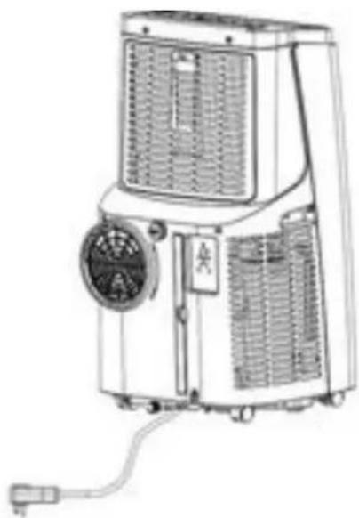
PRODUCT DIAGRAM
natural_image
Line drawing of a portable air conditioner unit with wheels and a handle (no text or symbols)FRONT VIEW
natural_image
Line drawing of an air conditioning unit with fan and control panel (no text or symbols)BACK VIEW
| Model | MAC-12000 | MAC-9000 |
| Cooling Capacity 12000 Btu (3,53 Kw) | 9000 Btu (2,63 kW) | |
| Heating Capacity | 8 | 0 |
| Power Supply | 2 | 2 |
| Cooling Rated Input Power/Current | 1357 W | 1010 W |
| Hrating Rated Input Power/Current | 1020 W | 843 |
| Noise Level | 6 | 5 |
| Maximum Refrigerant Charge | R 2 | 9 |
| Net Weight | 26,0 kg | 25,5 kg |
| Maximum Design Pressure Exhaust Suction | 1,8 MPa 0,6 MPa | 1,8 MPa 0,6 MPa |
| Minimum Room Size | 10 m^2 | 10 m^2 |
| Fuse type and rating: | 5ET/SMT, AC 250V, 3.15A | 5ET/SMT, AC 250V, 3.15A |
The Max operation temperature for the air conditioner Cooling: 35/24°C; heating: 20/12 °C; Temperature operation range: 7-35°C.
0
0
0
Unpacking
Unpack the carton and take the appliance and accessories out.
Check the device after unpacking for any damage or scratches on it.
Accessories:
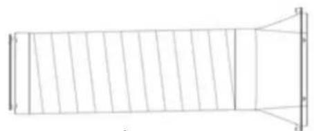
- Exhaust Pipe Assembly
- Window Sealing Plate Assembly
natural_image
Pure technical line drawing of a rectangular structure with internal vertical divisions and a right-angle triangular extension (no text or symbols)1

natural_image
Simple line drawing of a rectangular shape with an oval cutout on the left side (no text or symbols)2
Place the unit on a firm, level surface in an area with at least 50cm of free space around it allow for proper air circulation.
Do not operate in close proximity to walls, curtains, or other objects that may block inlet and outlet. Keep the air inlet and outlet free of obstacles.
If tipped more than 45°, allow the unit to set upright for at least 24 hours before start up.
Never install the unit where it could be subject to:
- Heat sources such as radiators, heat registers, stoves or other products that products that produce heat.
- Direct sunlight
- Mechanical vibration or shock
- Excessive dust
- Lack of ventilation, such as cabinet or bookcase
- Uneven surface
WARNING! Install
Install the unit in rooms which exceed 10 m ^2 .Do not install the unit in a place where
i n f l a m m a b l e
g a
Attach the exhaust hose
The air conditioner requires being vented outside so that the exhaust air can escape the room which coming from the appliance contains waste heat and moisture.
Do not replace or extend exhaust hose which will result in decreased efficiency, even worse shut down the unit due to low backpressure.
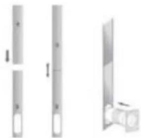
Step 1: Extend the adjustable window kit the length of your window. Connect the exhaust hose to the window kit.
natural_image
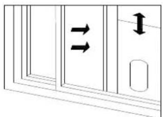
Three technical illustrations of vertical cylindrical components with internal cutouts, shown from different angles (no text or symbols)Step 2: Close your window to secure the kit in place. It needs to hold the windows kit firmly in place, secure the window kit with duct tape if required. It is recommended that the gap between the adapter and the sides of the window should be sealed off for maximum efficiency.
natural_image
Pure diagram of a door with double-headed arrows indicating direction, no text or symbols present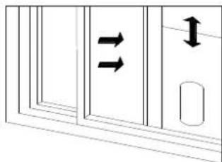
natural_image
Pure diagram of a door with double-headed arrows indicating direction, no text or symbols presentStep 3: Attach the hose connector to the exhaust air outlet of unit.
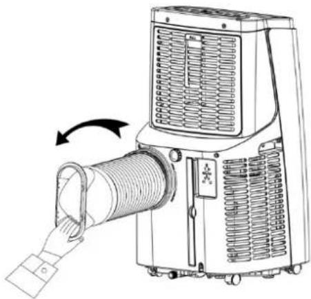
natural_image
Line drawing of an air conditioner unit with a hand inserting a hose (no text or symbols)Step4: Adjusting the length of the flexible exhaust hose, and avoid bends in the hose. Then place AC near an electrical outlet.
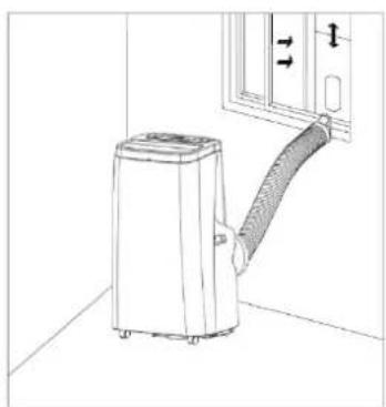
natural_image
Line drawing of a portable air conditioner unit connected to a door (no text or symbols)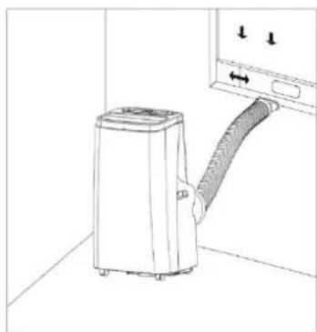
natural_image
Line drawing of a portable air conditioner unit with a coiled hose, connected to a wall-mounted door (no text or symbols)Step7: Adjust the louver at the air outlet, and then switch on the unit
Control Panel and Display
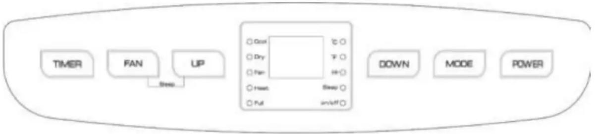
flowchart
graph LR
    A["TIMER"] --> B["FAN"]
    B --> C["UP"]
    C --> D["Down"]
    D --> E["MODE"]
    E --> F["POWER"]
    C --> G["Sleep"]
    G --> H["Cool"]
    G --> I["Dry"]
    G --> J["Fan"]
    G --> K["Head"]
    G --> L["Full"]
    G --> M["Sweep"]
    G --> N["In/Off"]
1: When the machine is powered on for the first time, the buzzer will play power-on music, and then the machine will get into standby status.
2: Power Key: press the key to turn on and turn off the machine. In the case of power on, press the key to turn off the machine; in the case of power off, press the key to turn on the machine.
3: Mode Selection Key: In the case of power on, press the key to switch between cooling fan dehumidifying mode.
4: Up Key and Down Key: press the two keys to change the setting temperature or setting time, operate as follows:
While setting temperature, press up key or down key to select the required temperature (not available in fan or dehumidifying mode).
While setting time, press up key or down key to select the required time.
5: Wind Speed Selection Key:
1) In cooling and fan mode, press the key to select high, low wind speed operation. But limited by
anti-cold conditions, under certain conditions, it may not run according to the set wind speed.
2) In dehumidifying mode, pressing the key is invalid, and the fan will forcibly choose low wind speed operation.
6: Timing Key:
In the case of power on, press the key to close timing; in the case of power off, press the key to open timing.
Press the key, when the timing symbol flashes, press up and down key to select the required timing value.
Timing values can be set in 1-24 hours and the timing value is adjusted up or down by one hour.
7: Sleep Mode:
In the cooling Mode, Press the UP and Fan Key to turn on the sleep mode, then the unit will work on Energy-Saving and quiet type.
Remote control
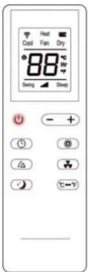
Instructions of key operation of the high-quality remote control are as follows:
- Power: Press the key to turn on or turn off the machine.
- Mode: press the key to switch between cooling, dehumidification, fan and heating (single cold with no such function) mode.
- Up: press (+) he key to increase temperature and timing set value.
- Down: press the key to reduce temperature and timing set value.
- Fan: press the key to select high, medium and low wind speed output circularly.
- Timer: press the key to set timing value. Timing value can be set with 1-24 hours and the timing value is adjusted upwards or downwards by one hour.
- Cleaning: Press Ⓞ louver will swing up and down.
- press the key to switch between Celsius and Fahrenheit.
- Sleep Mode: Press the key to turn on the sleep mode.
Cooling your room
Select the cool mode to lower the temperature in your room.
Press MODE button repeatedly until the LED of COOL operation lights up.
Press UP/DOWN button to adjust the temperature which is displayed on the screen.
Heating your room
Press MODE button repeatedly until the LED of HEAT operation lights up.
Press UP/DOWN button to set the temperature higher than the room temperature. The fan speed can also be set.
Note: The drainage hose should be attached to the unit for continuous operating.
Ventilating your room
Press MODE button repeatedly until the LED of FAN operation lights up.
In ventilation mode the room air is circulated, but not cooled.
Press FAN button repeatedly to select the fan speed as desired
Dehumidifying your room
Press DEHUM button or mode button on the remote control, the LED of DEHUM operation lights up. The fan speed is unable to select. User should connect the hose to the drain outlet at the bottom of the unit. The drain hose is needed as well as in heat operation mode.
Note: in this mode, the fan speed switches over to low speed and cannot be selected.
Sleep mode
The sleep mode can be activated when in cool mode and heat mode.
Protection function
Frost Protection Function:
In cooling, dehumidifying or economic power saving mode, if the temperature of the exhaust pipe is too low, the machine will automatically enter protection status; if the temperature of the exhaust pipe rises to a certain temperature, it can automatically revert to normal operation.
Overflow Protection Function:
When water in the water pan exceeds the warning level, the machine will automatically sound an alarm, and the "FULL" indicator light will flash. At this point, you need to move the drainage pipe connecting the machine or the water outlet to sewer or other drainage area to empty the water (details see Drainage Instructions at the end of this chapter). After the water is emptied, the machine will automatically return to the original state.
Automatic Defrosting (cooling models have this function): The machine has automatic defrosting function. Defrosting can be achieved through four - way valve reversing.
Protection Function of the Compressor
To increase the service life of the compressor, it has a 3-minute delay booting protection function after the compressor is turned off.
Drainage
Unscrew the drainage cover and unplug the water plug, the water will automatically flow into the water container.
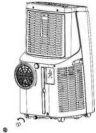
natural_image
Line drawing of a portable air conditioner unit with fan and cooling fan (no text or symbols)Continuous drainage (Optional) (only applicable to dehumidifying mode), as shown in figure:
1) Unscrew the drainage cover, and unplug the water plug.
2) Set the drainage pipe into the water outlet.
3) Connect the drainage pipe to the bucket.
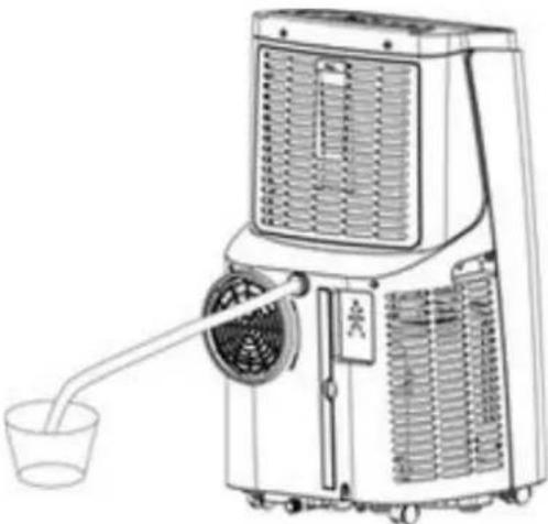
natural_image
Line drawing of an air conditioner unit with a cup pouring liquid from a side arm (no text or symbols)To avoid water spillage:
- As the negative pressure of condensate drain pan is large, tilt the drain hose downward toward the floor. It is appropriate that the degree of inclination should exceed 20 degrees.
- Straighten the hose to avoid a trap existing in the hose.
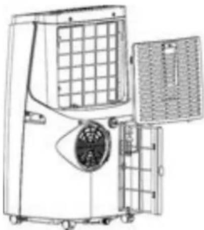
Cleaning the Air Filter (every two weeks)
Dust collects on the filter and restricts the airflow. The restricted airflow reduces the efficiency of the system and if it becomes blocked it can cause damage to the unit.
The air filter requires regular cleaning. The air filter is removable for easy cleaning. Do not operate the unit without an air filter, or the evaporator may be contaminated.
-
Clean the machine with a soft wet cloth.
-
Remove the filter mesh from the unit.
-
Use a clean rag to absorb the surface dust on the filter mesh. If the filter is extremely dirty, use tap water to flush the filter. Fully dry the filter before putting it back into the air inlet fence. A clean filter will increase the machine's capacity.
natural_image
Technical line drawing of an air conditioning unit with fan and vent (no text or symbols)Warning!!!
Do not touch the evaporator surface with bare-hand, or could cause injury of your fingers.
CLEANING UP OF REFRIGERANT
General Measures:
- Gas/vapor heavier than air. May accumulate in confined spaces, particularly at or below ground level.
- Eliminate every possible source of ignition.
- Use appropriate personal protection equipment (PPE).
- Evacuate unnecessary personnel, isolate, and ventilate area.
- Do not get in eyes, on skin, or on clothing. Do not breathe vapors or gas.
- Prevent entry to sewers and public waters.
- Stop the source of the release, if safe to do so. Consider the use of water spray to
d i s p e r s e v a p o
- Isolate the area until gas has dispersed. Ventilate and gas test area before entering.
C o n t a c t c o m p e
TROUBLESHOOTING
| Symptom Inspection Solution | ||
| The unit is not operating. Check the power connection in securely.Check if the water level indicator lights up?Check the room temperature. | Insert the power cord securely into the wall Outlet Empty the water tank and reinstall correctly.The range of operating temperature is 5-35°C. | |
| The unit does not cool/heat as it setting | Check the air filter for dirtCheck if the air duct is blocked.Check if the room temperature is too low or too hot.Set temp. level is higher/lower than currentTemperature | Clean the air filter as necessary.To dear the obstacle.This is normal. Allowing for more time to cool down when the unit is first turned on.Set the temperature at proper set-point according the manual. |
| Water Leakage | Overflow while moving the unit.Check if the drain hose is kinked or bends. | Empty the water tank before transportStraighten the hose to avoid a trap existing. |
| Excessive Noise | Check if the unit is securely positioned.Check if any loose, vibrating parts.Noise sounds like water lowing. | Place the unit on horizontal and firm groundSecure and tight the parts. Noise comes from flowing refrigerant. This is normal. |
STORAGE
Long-Term Storage - If you will not be using the unit for an extended period of time (more than a few weeks) it is best to clean the unit and dry it out completely. Please store the unit per the following steps:
- Unplug the unit.
- Drain the remaining water from the unit.
- Clean the filter and let the filter dry completely in a shaded area.
- Collect the power cord at the water tank.
- Re-install the filter at its position.
- Preserving the machine in ventilating, dry, non-corrosive gas and safe place indoor.
- The unit must be kept in upright position when in storage
ATTENTION:
The evaporator inside the machine has to be dried out before the unit is packed to avoid component damage and molds. Unplug the unit and place it in a dry open area for days to dry it out. Another way to dry the unit is to set the humidity point more than 5% higher than the ambient humidity to force the fan to dry the evaporator for a couple of hours.
WARNING!!!
Releasing refrigerant into atmosphere is strictly forbidden!
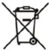
| T | h | e | s | y | m | b | o | l | ||
| o | t | h | e | r | h | o | u | s | e | |
| electronic equipment collection point where a suitable system is created to allow safe disposal | ||||||||||
| o | f | t | h | e | s | e | i | t | ||
| D | a | n | g | e | r | o | u | s | c | |
consequences for the environment and human health therefore correct handling of the equipment is very important. Certain substances which may adversely affect the environment over the life of the product and after use have been limited in this device.
Product fiche
| Supplier's name or trade mark RAVANSON LTD. Sp. z o.o. | ||
| Model identifier MAC-12000 MAC-9000 | ||
| Sound power level | 65 | |
| The name and GWP of the refrigerant used | R290 / 3 | |
| Refrigerant leakage contributes to climate change. Refrigerant with lower global warming potential (GWP) would contribute less to global warming than a refrigerant with higher GWP, if leaked to the atmosphere. This appliance contains a refrigerant fluid with a GWP equal to 3. This means that if 1 kg of this refrigerant fluid would be leaked to the atmosphere, the impact on global warming would be 3 times higher than 1 kg of CO2, over a period of 100 years. Never try to interfere with the refrigerant circuit yourself or disassemble the product yourself and always ask a professional. | ||
| Energy Efficiency Class | A2,60 ≤ EER < 3,10A3,10 ≤ COP < 3,60 | A2,60 ≤ EER < 3,10A2,30 ≤ COP < 2,60 |
| The indicative hourly electricity consumption Q SDw kWh/60 min | 1,3571,020 | 1,0100843 |
| Energy consumption “X,Y” kWh per 60 minutes, based on standard test results. Actual energy consumption will depend on how the appliance is used and where it is located. | ||
| The cooling capacity Prated (kW) | 3,53 | 2,64 |
| The heating capacity Prated (kW) | 2,58 | 2,07 |
| M | ||||
| Description Symbol Unit Value Value | ||||
| Rated cooling efficiency P | rated C k | W 3,53 2,64 | ||
| Rated heating efficiency P | rated | k | W | 2 |
| Nominal power consumption Cooling | P_EER | kW | 1,357 | 1,010 |
| Nominal power consumption Heating | P_COP | kW | 1,020 | 0,843 |
| Rated energy efficiency ratio | EERd | - | 2,61 | 2,63 |
| Rated efficiency ratio | COPd | - | 2,54 | 2,46 |
| Power consumed with the thermostat off | P_TO | W | - | - |
| Power consumption in standby mode | P_SB | W | 1,0 | 0,46 |
| Power consumption of single-/dual-channel air-conditioners | SD: Q_SD DD: Q_DD | SD: kWh/hDD: kWh/a | 1,3571,020 | 1,0100,843 |
| Sound power | LWA | dB (A) | 65 | 65 |
| Global Warming Potential | GWP | kg równoważników CO2 | 3 | 3 |
| Further information can be obtained from | RAVANSON LTD Sp. z o.o. ul.Mazowiecka 6, 09-100 Płońsk | |||
A
5
8
SV

| L | ä | s | n | o | g | g | r | a | n | t | |
| a | p | p | a | r | a | t | e | n | f | ö | |
| r | e | f | e | r | e | n | s | . | |||
| N | ä | r | d | u | a | n | v | ä | n | ||
| a | k | t | t | a | g | r | u | n | d | l | |
| r | i | s | k | e | n | f | ö | r | b |

S E R V I C E H A N D B
PRODUKTSHEMA
natural_image
Line drawing of a portable air conditioner unit with wheels and a handle (no text or symbols)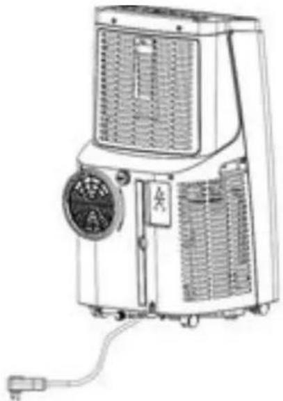
natural_image
Line drawing of an air conditioning unit with cooling fan, vent, and power outlet (no text or symbols)Framsida
Baksida
Framsida
Baksida
| Model | MAC-12000 | MAC-9000 |
| Kylkapacitet 12000 Btu (3,53 kW) 9000 Btu (2,63 kW) | ||
| Värmekapacitet 8000 Btu (2,58 kW) 7000 Btu (2,05 kW) | ||
| Nominell ström 220 – 240 V; 50 Hz 220 – 240 V; 50 Hz | ||
| Kylning.Nominellt effektbehov | 1357 W | 1010 W |
| Uppvärmning.Nominellt effektbehov / ström | 1020 W | 843 |
| Bullernivå 65 dB(A) 65 dB(A) | ||
| Maximal mängd köldmedium R290/230 g | R290/230 g | |
| Nettovikt 26,0 kg 25,5 kg | ||
| Maximalt dimensioneringstryckUttömma Sugning | 1,8 MPa0,6 MPa | 1,8 MPa0,6 MPa |
| Minsta rumsstorlek | 10 m^2 | 10 m^2 |
| Säkringstyp och -effekt | 5ET/SMT, AC 250V,3.15A | 5ET/SMT, AC 250V,3.15A |
Maximal drifttemperatur för luftkonditioneringsapparaten
natural_image
Pure technical line drawing of a mechanical component or structural frame without any text, numbers, or symbols1

natural_image
Simple line drawing of a rectangular shape with an oval cutout on the left side (no text or symbols)2
UPPSTÄLLNING
natural_image
Three technical illustrations of vertical cylindrical components with mounting holes, shown from different angles (no text or symbols)natural_image
Diagram showing two double-headed arrows pointing to a window frame with a handle (no text or symbols)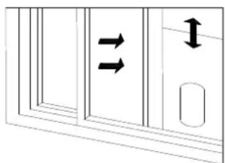
natural_image
Pure diagram of a door with double-headed arrows indicating flow or movement, no text or symbols presentnatural_image
Line drawing of a portable air conditioner unit with a hand inserting a hose (no text or symbols)natural_image
Line drawing of a portable air conditioner unit with a coiled hose, placed near a door (no text or symbols)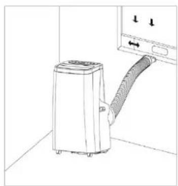
natural_image
Line drawing of a portable air conditioner unit with airflow direction indicator (no text or symbols)natural_image
Line drawing of an air conditioner unit with fan and cooling fan (no text or symbols)natural_image
Line drawing of an air conditioner unit with a cup pouring liquid from the side arm (no text or symbols)natural_image
Technical line drawing of an air conditioning unit with fan and vent (no text or symbols)Varning!!!
S E R V I C E H Å N D B
PRODUKTSKJEMA
natural_image
Line drawing of a portable air conditioner unit with wheels and a handle (no text or symbols)Front Bak
natural_image
Line drawing of an air conditioning unit with control panel and power outlet (no text or symbols)natural_image
Pure technical line drawing of a rectangular structure with internal vertical divisions and triangular ends (no text or symbols)1

natural_image
Simple line drawing of a rectangular shape with an oval cutout on the left side (no text or symbols)2
OPPSTILLING
natural_image
Three vertical metal bars with cutouts and a separate bracket, shown from different angles (no text or symbols)natural_image
Pure diagram of a door with double-headed arrows indicating direction, no text or symbols present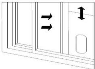
natural_image
Diagram of a door with double-headed arrows indicating flow or movement, no text or symbols presentnatural_image
Illustration of a portable air conditioner unit with a hand inserting a hose (no text or symbols visible)natural_image
Line drawing of a portable air conditioner unit next to a door with a hose (no text or symbols)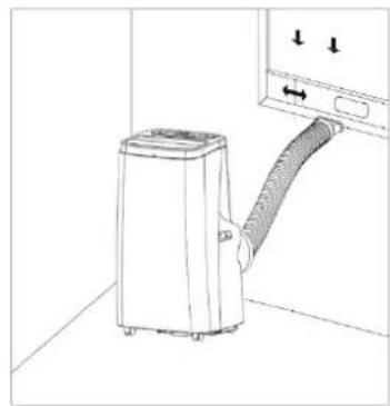
natural_image
Line drawing of a portable air conditioner unit with a hose inserted, showing airflow direction (no text or symbols)natural_image
Line drawing of an air conditioning unit with fan and cooling fan (no text or symbols)Kontinuerlig drenering (gjelder kun avfuktingsmodus) som vist på tegningen:
natural_image
Line drawing of a small outdoor air conditioner unit with a glass tube and cup, no text or symbols presentnatural_image
Technical line drawing of a mechanical device with internal components and mounting bracket (no text or symbols)Advarsel!!!
- Ravanson®
- USTAWIENIE
- Ostrzeżenie!!!
- PLEASE NOTE!
- WARNING!
- Symbols
- Unpacking
- Never install the unit where it could be subject to:
- WARNING! Install
- Attach the exhaust hose
- Control Panel and Display
- 5: Wind Speed Selection Key:
- 6: Timing Key:
- 7: Sleep Mode:
- Remote control
- Cooling your room
- Heating your room
- Ventilating your room
- Dehumidifying your room
- Sleep mode
- Protection function
- Frost Protection Function:
- Overflow Protection Function:
- Protection Function of the Compressor
- Drainage
- Continuous drainage (Optional) (only applicable to dehumidifying mode), as shown in figure:
- To avoid water spillage:
- Cleaning the Air Filter (every two weeks)
- Warning!!!
- CLEANING UP OF REFRIGERANT
- General Measures:
- TROUBLESHOOTING
- STORAGE
- ATTENTION:
- Releasing refrigerant into atmosphere is strictly forbidden!
- PRODUKTSHEMA
- UPPSTÄLLNING
- Varning!!!
- PRODUKTSKJEMA
- OPPSTILLING
- Kontinuerlig drenering (gjelder kun avfuktingsmodus) som vist på tegningen:
- Advarsel!!!
Brand : Ravanson
Model : MAC-12000
Category : Heating