
V35P - Tripod Camgear - Free user manual and instructions
Find the device manual for free V35P Camgear in PDF.


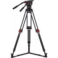
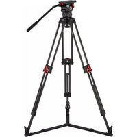
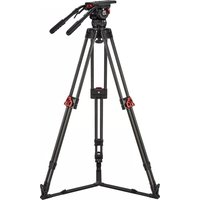
| Product Type | Professional Tripod |
| Brand | Camgear |
| Model | V35P |
| Maximum Height | 170 cm |
| Minimum Height | 35 cm |
| Folded Length | 85 cm |
| Weight | 5.2 kg |
| Maximum Load | 30 kg |
| Leg Sections | 3 |
| Lock Type | Flip locks |
| Head Type | Fluid head (optional, not included) |
| Material | Aluminum alloy |
| Bubble Level | Yes |
| Spreader | Mid-level spreader |
| Feet | Spiked feet with rubber pads |
| Power Supply | None (manual operation) |
| Maintenance | Clean with dry cloth; lubricate moving parts as needed |
| Safety | Ensure locks are tight before use; avoid overloading |
| Spare Parts Availability | Contact Camgear authorized service centers |
| Repairability | Modular design; parts can be replaced individually |
Frequently Asked Questions - V35P Camgear
User questions about V35P Camgear
0 question about this device. Answer the ones you know or ask your own.
Ask a new question about this device
Download the instructions for your Tripod in PDF format for free! Find your manual V35P - Camgear and take your electronic device back in hand. On this page are published all the documents necessary for the use of your device. V35P by Camgear.
USER MANUAL V35P Camgear
natural_image
Technical illustration of a mechanical device with a red diamond symbol overlay (no text or symbols present)Copyright © 2017
All right reserved throughout the world.
No part of this document may be stored in a retrieval system, transmitted, copied or reproduced in any way including, but not limited to, photocopy, photograph, magnetic or other record without the prior agreement and permission in writing of Camgear Inc.
Disclaimer
The information contained in this publication is believed to be correct at the time of printing.
Camgear Inc. reserves the right to make changes to the information or specifications without obligation to notify any person of such revision or changes.
Changes will be incorporated in new versions of the publication.
Camgear reserves the right to make changes to product design and functionality without notification.

are registered trademarks of Camgear Inc.
Published by
Camgear Inc.
Content
Safety 4
Left View 5
Right View 6
Installation 7
Illuminated Level Bubble 7
Mounting and Leveling the Head 7
Mounting and Dismounting the Camera 8
Mounting and Adjusting the Pan Bar 9
Configuring the Pan Bar 9
Balancing the Payload 10
Adjusting the Centre of Gravity (C of G) 10
Adjusting the Counterbalance 12
Adjusting the Drags 14
Transportation 14
Maintenance 15
Safety
Important information on the safe installation and operation of these products. Read this information before operating the products.
For your personal safety, read these instructions. Do not operate the product if you do not understand how to use it safely.
Save these instructions for future reference.
Warning Symbols Used in these Instructions

Where there is a risk of personal injury, injury to others, or damage to tripod system or associated equipment, comments appear, highlighted by the word 'WARNING!'. And supported by the warning triangle symbol.

Where there is a risk of damage to the product, associated equipment, process or surroundings, comments appear supported by the word 'CAUTION!'. And supported by the warning triangle symbol.
Health and Safety

WARNING! Risk of personal injury or injury to others. All personnel must be fully trained and adhere to correct manual handling techniques and Health & Safety regulations. It is the responsibility of the local organisation to enforce safe working practices at all times.
Mounting and Installation

WARNING! Do not install a head to a tripod that cannot support the combined mass weight of the head and its full payload.

WARNING! Risk of finger entrapment. Do not place fingers between the platform and the body of the fluid head.

CAUTION! Always lock the pan and tilt brakes when the camera is mounted but not in use or when levelling the fluid head on the tripod.

CAUTION! Hold the camera securely when mounting or dismounting camera from the fluid head and when making adjustments to the tripod height or footprint.

CAUTION! Always hold the pan bar when making adjustments to the counterbalance or camera position. Do not use the pan bar to lift or move the tripod and fluid head.

CAUTION! Do not attach heavy items to the pan bar and always remove the camera before transporting.

| 1 | Tilt brake |
| 2 | Quick release lock lever |
| 3 | Quick release safety button |
| 4 | Counterbalance control |
| 5 | Payload range shifter (boost button) |
| 6 | Battery compartment for level bubble |
| 7 | Illuminated level bubble |
| 8 | Tilt drag control |
| 9 | Rosette for left pan bar |
Right View

| 1 | Wedge plate |
| 2 | Sliding plate |
| 3 | Pan brake |
| 4 | Pan drag control |
| 5 | Bowl clamp |
| 6 | Sliding plate lock lever |
| 7 | Rosette for right pan bar |
Installation (1-8)
Illuminated Level Bubble
The fluid head is fitted with an illuminating level bubble which allows easy levelling in poor lighting conditions. The illumination is activated by firmly tapping the button and will automatically switch off after approximately 60 seconds.
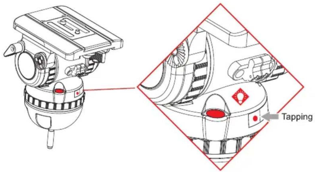
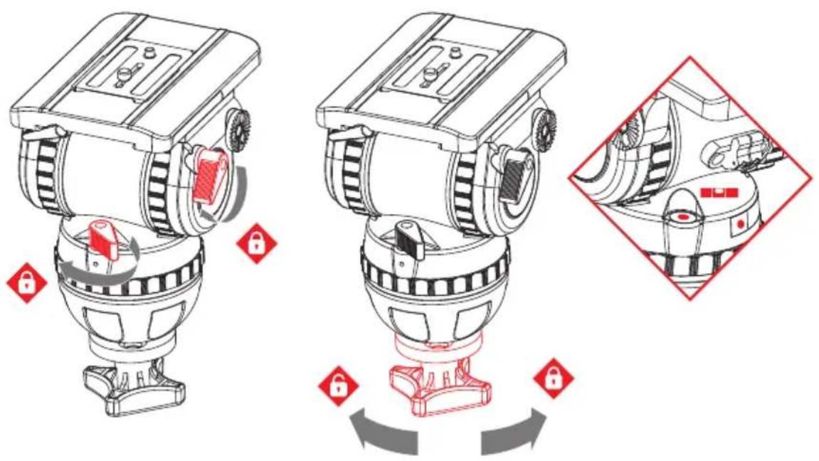
Mounting and Leveling the Head
- Apply the pan and tilt brakes and hold the head firmly with one hand.
- Remove the bowl clamp and place the fluid head on the tripod refitting the bowl clamp loosely. Tighten the tie down and check the level bubble remains central when the head is rotated through a full 360°.
Installation (2/8)
Mounting and Dismounting the Camera
-
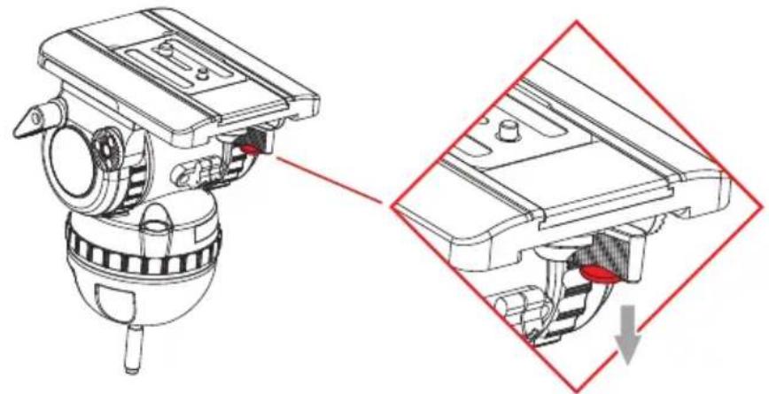
Apply the pan and tilt brakes.
-
Hold the camera plate or camera with one hand. Grasp the quick release lever with your thumb and index finger and pull down the safety button.
natural_image
Technical illustration of a mechanical device with a close-up view showing internal components and a red arrow indicating a downward motion (no text or symbols present)- With the safety button held down, move the lever as far as possible to the left.

natural_image
Technical illustration of a mechanical device with a close-up view showing internal components and directional arrows (no text or symbols)- The camera plate or camera will be released from the sliding plate.

natural_image
Technical line drawing of a mechanical device with red annotation lines indicating assembly or detail (no text or symbols present)-
Attach the camera plate to the camera around its centre of gravity.
-
Mount the camera plate and camera onto the sliding plate. It will lock automatically and the lever will click audibly back.
Installation (3/8)
Mounting and Adjusting the Pan Bar
Fit and adjust the pan bar to the desired position, tighten the clamp lever ensuring the teeth mesh fully.
To adjust the position of the pan bar, loosen the clamp lever sufficiently to allow the rosettes to rotate without attaching the teeth of rosette.

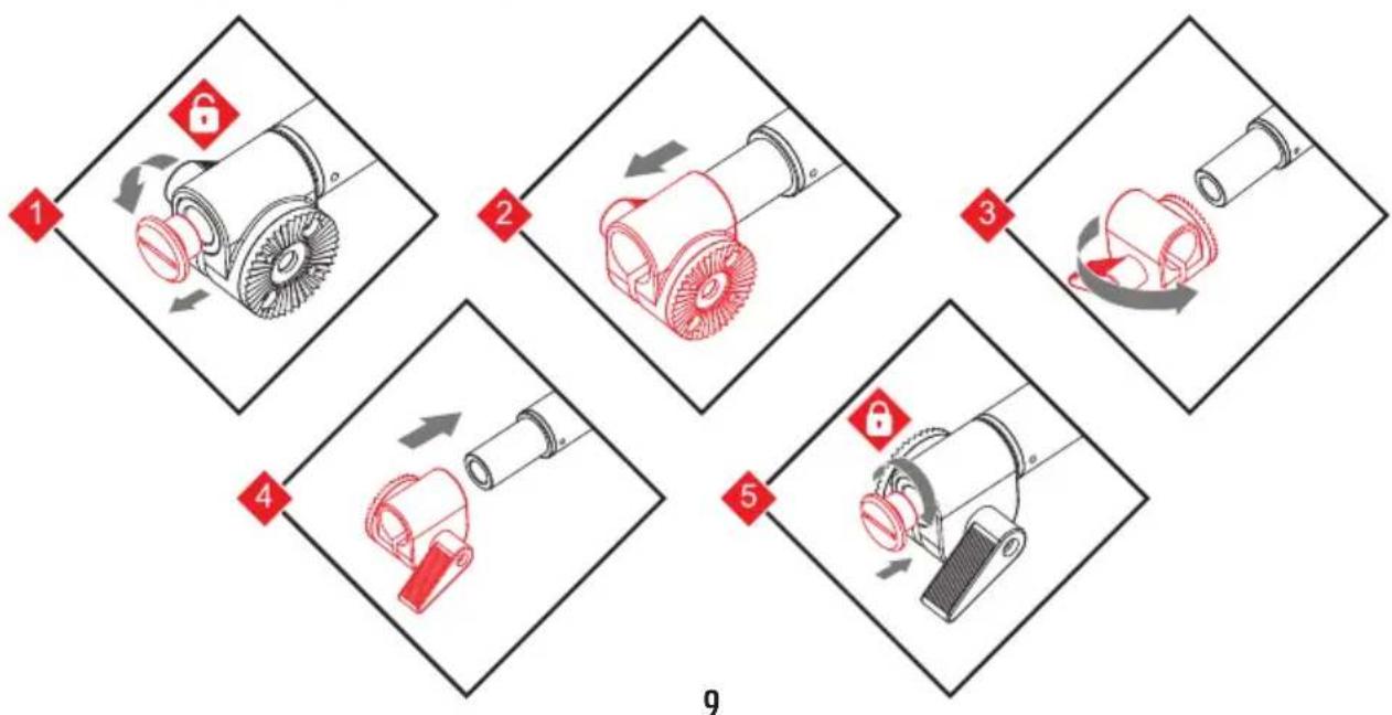
Configuring the Pan Bar
As standard, the pan bar is configured to mount on the right hand side of the fluid head. The pan bar can be configured for left hand
flowchart
graph TD
    A["1: Component 1"] --> B["2: Component 2"]
    B --> C["3: Component 3"]
    C --> D["4: Component 4"]
    D --> E["5: Component 5"]
    E --> F["6: Component 6"]
Installation (4/8)
Balancing the Payload
Before operating the fluid head, the payload (camera, lens and any other fitted accessories) must be correctly balanced to ensure safe and reliable operation.

WARNING! When balancing the payload, it is important to be aware of the potential danger that an unbalanced payload will fall away suddenly. Maintain a firm hold on the payload until the balance is set correctly.

WARNING! Risk of finger entrapment. Do not place fingers between the platform and the body of the fluid head.

CAUTION! Always hold the pan bar when making adjustments to the counterbalance or camera position.

CAUTION! The camera, pan bars and all fitted accessories must be mounted in their operational position before balancing the head. Any equipment fitted or adjusted later can break the balance status of the fluid head.
Adjusting the Centre of Gravity (C of G)
Before adjusting the counterbalance, the centre of gravity (C of G) of the payload must be centred precisely over the axis of the fluid head.

CAUTION! Ensure that the fluid head is level before adjusting the centre of gravity.
- Apply the tiltl brake and adjust the tilt drag to "1". Set the counterbalance control to lowest step, switch off the payload range shifter (boost button) and keep holding the camera. Note moving the counterbalance from one setting to another requires the head to pass the horizontal position to take affect.

Installation (5/8)
- Estimate the overall weight of the payload. Based on the overall weight, switch one boost button or numbers of boost buttons on as appropriate. Note switching the boost buttons takes affect as the fluid head passes the horizontal position.
V15P (with one boost button)
| Button off | 0-11.2 kg/0-24.7 lbs |
| Button on | 9.3-20.5 kg/20.5-45.2 lbs |
V20P (with one boost button)
| Button off | 0-16.8 kg/0-37 lbs |
| Button on | 9.3-26.1 kg/20.5-57.5 lbs |
V20S (with two boost buttons)
| Two button off | 0-11.2 kg/0-24.7 lbs |
| One button on | 9.3-20.5 kg/20.5-45.2 lbs |
| Two button on | 18.6-29.8 kg/41-65.7 lbs |
V25P (with two boost buttons)
| Two button off | 0-16.8 kg/0-37 lbs |
| One button on | 9.3-26.1 kg/20.5-57.5 lbs |
| Two button on | 18.6-35.4 kg/41-78 lbs |
V35P (with three boost buttons)
| Three button off | 0-16.8 kg/0-37 lbs |
| One button on | 9.3-26.1 kg/20.5-57.5 lbs |
| Two button on | 18.6-35.4 kg/41-78 lbs |
| Three button on | 27.9-44.7 kg/61.5-98.5 lbs |
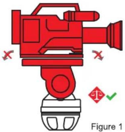
- Hold the pan bar firmly, disengage the tilt brake. Observe how the payload moves and where it stops. If the platform stops in a horizontal position (camera pointing directly forward) or falls away evenly in either direction, the balance is correct. (Figure 1)
- If the payload falls away in either direction (front or back heavy):
(A) Unlock the sliding balance plate by pushing back the red lever underneath the balance plate as far as possible. (Figure 2)
natural_image
Red video camera with warning symbols and a checkmark, labeled Figure 1 (no text or symbols on the device itself)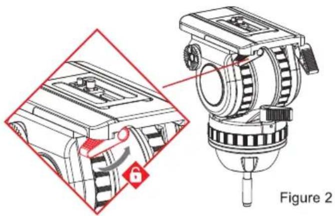
Installation (6/8)
(B) If the payload tilts backwards, slide it towards the front of the fluid head. Re-lock the sliding balance plate.

natural_image
Two red video cameras with camera bodies and motion arrows indicating rotation (no text or symbols)(C) If the payload tilts forwards, slide it towards the rear of the fluid head. Re-lock the sliding balance plate.

natural_image
Two red video cameras with rotating arms, shown in side and top views (no text or symbols)(D) Re-check the movement of the payload. If further adjustment is required, repeat steps (A) to (C).
Adjusting the Counterbalance
The fluid head is equipped with payload range shifter (boost button) and multiple step counterbalance adjuster to accurately balance the payload.
Note: Moving the counterbalance from one setting to another requires the head to pass the horizontal position to take affect.
- Set the counterbalance adjustment knob to the mid-range setting.
Installation (7/8)
- Tilt the payload approximately 30^ in both directions and release it. If the payload stays in the same position when released, the payload is correctly balanced.

natural_image
Red video camera icon with no text or symbols
natural_image
Red video camera icon with no text or symbols, featuring a stylized graphic and red X marks (no readable text or symbols)- If the payload continues to move backwards when released, the balance is set too low. Raise the balance adjuster setting by one increment and retest.

natural_image
Red video camera with a rotating button, no text or symbols visible
- If the payload continues to move upwards when released, the balance is set too high. Lower the balance adjuster setting by one increment and retest.

natural_image
Red mechanical device with rotating arrow, no visible text or symbols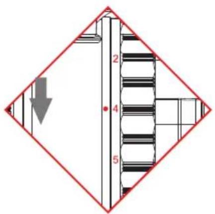
Installation (8/8)
- Tilt the payload through positive and negative angles of travel, checking that the payload remains at any angle of tilt unsupported.

natural_image
Two red video cameras with a green checkmark indicating selection (no text or symbols present)Note: If the payload angle falls away, repeat the balancing procedure (step 3 or 4) until balance is achieved.
Adjusting the Drags
The fluid head is equipped with multiple tilt and pan step drag controls. The drags help to eliminate jerks and vibrations when moving the fluid head during filming. The drags can also be fully disengaged.

CAUTION! Always set the drag to the index positions. Setting the drag between index positions can cause serious damage to the fluid head.
- Turn the pan and tilt drag to the required index position by aligning the index figure with the dot mark. Turn the brakes off and engage the drag by slowly panning or tilting the camera.
- Turn the drag controls to the 1 position to switch off the drag completely.
Transportation Head Settings
To ensure smooth and reliable operation over the long life of the fluid head, the following settings should be applied during transportation or periods of storage:
| Pan & Tilt Brake | OFF |
| Counterbalance | Maximum Step |
| Pan & Tilt Drags | Maximum Step |
Transporting with the Attached Pan Bar
To transport the fluid head with the pan bar attached, stow in the vertical position with the tripod legs to prevent damage.
Cleaning
Clean the fluid head regularly using a soft cloth. For heavier dirt use a soft brush and a mild detergent.
Changing the Battery
V12 fluid head is equipped the illuminated bubble level which is powered by two standard type button cell (CR1220, 3 V) located in the battery holder, which can be taken out by hand.

CAUTION! Make sure the correct polarity of the battery when replacing.
Routine Maintenance
Periodically operate the horizontal and vertical drags through their full range of indexing to ensure the engaging pins in fluid head stay lubricated.
- Copyright © 2017
- Disclaimer
- Content
- Safety 4
- Left View 5
- Right View 6
- Installation 7
- Transportation 14
- Maintenance 15
- Safety
- Warning Symbols Used in these Instructions
- Health and Safety
- Mounting and Installation
- Right View
- Installation (1-8)
- Illuminated Level Bubble
- Mounting and Leveling the Head
- Installation (2/8)
- Mounting and Dismounting the Camera
- Installation (3/8)
- Mounting and Adjusting the Pan Bar
- Configuring the Pan Bar
- Installation (4/8)
- Balancing the Payload
- Adjusting the Centre of Gravity (C of G)
- Installation (5/8)
- Installation (6/8)
- Adjusting the Counterbalance
- Installation (7/8)
- Installation (8/8)
- Adjusting the Drags
- Transportation Head Settings
- Transporting with the Attached Pan Bar
- Cleaning
- Changing the Battery
- Routine Maintenance
Brand : Camgear
Model : V35P
Category : Tripod