
HC24TB-4-2R-2 - Beer dispenser Perlick - Free user manual and instructions
Find the device manual for free HC24TB-4-2R-2 Perlick in PDF.


| Product Type | Beer Dispenser (Undercounter) |
| Brand | Perlick |
| Model | HC24TB-4-2R-2 |
| Dimensions (W x D x H) | 24 x 24 x 34 inches (610 x 610 x 864 mm) |
| Weight | 120 lbs (54 kg) |
| Power Supply | 115V / 60Hz, 5 amps |
| Cooling Type | Self-contained forced air cooling |
| Temperature Range | 38 – 42 °F (3 – 6 °C) |
| Number of Taps | 4 |
| Number of Kegs Capacity | 2 (half-barrel or slim quarter kegs) |
| Refrigerant Type | R290 (environmentally friendly) |
| NEMA Plug Configuration | 5-15P |
| Condenser Location | Right side (ventilated) |
| Main Functions | Beer dispensing, cooling, foam control |
| Cleaning and Maintenance | Weekly cleaning of drip tray; monthly coil cleaning; annual condenser cleaning |
| Safety Features | Leveling legs, automatic defrost, high-temperature alarm |
| Spare Parts Availability | All major components (tower, faucets, thermostat, fan) available via authorized Perlick distributors |
| Repairability | Modular design; user-replaceable parts for common failures |
| Warranty | 1 year parts and labor (limited) |
Frequently Asked Questions - HC24TB-4-2R-2 Perlick
User questions about HC24TB-4-2R-2 Perlick
0 question about this device. Answer the ones you know or ask your own.
Ask a new question about this device
Download the instructions for your Beer dispenser in PDF format for free! Find your manual HC24TB-4-2R-2 - Perlick and take your electronic device back in hand. On this page are published all the documents necessary for the use of your device. HC24TB-4-2R-2 by Perlick.
USER MANUAL HC24TB-4-2R-2 Perlick
| PROCEDURE FOR SWITCHING DIRECTION OF DOOR SWINGON PERLICK C-SERIES, 15 INCH, AND SIGNATURE SERIES CABINETS | |||
| NOTE: Changing the door mount is not advisable if you have a door with custom wood overlay.doing so may result in having a handle that is in an undesirable position. | |||
| Required:-Large Flat-Head Screwdriver-Regular Phillips-Head Screwdriver-Hinge Kit from Perlick-Plastic Putty Knife | HINGE KITSPart number 67439R to switch to Right HingingPart number 67439L to switch to Left Hinging | ||
 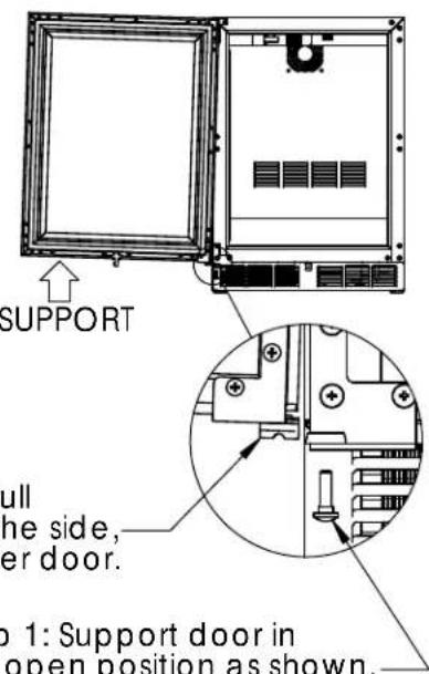 Step 2: Pdoor to tthen lowStep 4: Remove the Hole Plugsfrom the Top and Bottom HingeBracket mounting holes. Thenplace them in the holes on theopposite side made vacantin Step 3. Step 2: Pdoor to tthen lowStep 4: Remove the Hole Plugsfrom the Top and Bottom HingeBracket mounting holes. Thenplace them in the holes on theopposite side made vacantin Step 3. Step 5: Using thescrews from Step 3,-install the new Topand Bottom CabinetHinge Brackets. Step 5: Using thescrews from Step 3,-install the new Topand Bottom CabinetHinge Brackets.  Step 6: Removethe Top andBottom DoorHinge Bracketsand the PushPlunger Bracket.Save the screwsfor later. Step 6: Removethe Top andBottom DoorHinge Bracketsand the PushPlunger Bracket.Save the screwsfor later. | |||
 | Perlick CorporationMilwaukee, WI 53223 | DOOR HINGEREVERSAL | SCALE 1:24DRAWN 3/28/201167439 |
| THIS DOCUMENT/PUBLICATION/SOFTWARE/DRAWING CONTAINS PROPRIETARY INFORMATION WHICH IS THE PROPERTY OF THE PERLICK CORPORATION, IT MAY NOT BE REPRODUCED OR TRANSMITTED IN ANY FORM, ELECTRONCOR MECHANICAL, INCLUDING PHOTOCOPYING, RECORDING, OR USED IN ANYINFORMATION STORAGE, TRANSMISSION, OR RETRIEVAL SYSTEM, WITHOUT WRITTEN PERMISSION FROM THE PERLICK CORPORATIONCOPYRIGHT 2001 PERLICK CORPORATION. ALL RIGHTS RESERVED. | |||
PROCEDURE FOR SWITCHING DIRECTION OF DOOR SWING ON PERLICK C-SERIES, 15 INCH, AND SIGNATURE SERIES CABINETS

Step: 7 Remove the Front Panel from the Door Assembly by removing the inner mounting screws, 4 per side, from the perimeter of the assembly. Rotate the Front Panel 180°, the top becomes the bottom. Reattach using the same screws and mounting holes.
Step 8: Remove Perlick nameplate from Door Front using Plastic Putty Knife. Install new Perlick nameplate (included)
Step9: Insert bearing into Top Door Hinge Bracket.
Step 10: Insert V-block into Bottom Door Hinge Bracket, see NOTE below, and attach with E-Clip.
NOTE: ORIENTATION
Step 11: Attach the Top and Bottom Door Hinges and Push Plunger using screws removed in Step 6.
Step 12: Place Lower V-Block into Lower Cabinet Hinge with notch parallel to cabinet.
Step 13: Lift the Door Assembly and insert top pin into bearing. Then move door toward cabinet and align V-Blocks.
Step 14: Insert and tighten Lower Hinge Pin to complete assembly.

Perlick Corporation
Milwaukee, WI 53223
DOOR HINGE REVERSAL
SCALE 1:24
DRAWN DAS3/2010E1
67439
THIS DOCUMENT/PUBLICATION/SOFTWARE/DRAWING CONTAINS PROPRIETARY INFORMATION WHICH IS THE PROPERTY OF THE PERLICK CORPORATION. IT MAY NOT BE REPRODUCED OR TRANSMITTED IN ANY FORM, ELECTRONIC OR MECHANICAL, INCLUDING PHOTOCOPYING, RECORDING, OR USED IN ANYINFORMATION STORAGE, TRANSMISSION, OR RETREVAL SYSTEM, WITHOUT WRITTEN PERMISSION FROM THE PERLICK CORPORATION. COPYRIGHT 2001 PERLICK CORPORATION. ALL RIGHTS RESERVED.
Brand : Perlick
Model : HC24TB-4-2R-2
Category : Beer dispenser