MRT-327 - Intercom RTS - Free user manual and instructions
Find the device manual for free MRT-327 RTS in PDF.


| Product Type | Intercom System |
| Brand | RTS |
| Model | MRT-327 |
| Dimensions (approx.) | 150 mm × 80 mm × 30 mm (height x width x depth) |
| Weight (approx.) | 200 g |
| Power Supply | 12V DC, 500 mA (adapter included) |
| Main Functions | Two-way audio communication, door release, call button, night vision (if camera equipped), volume control |
| Connection Type | Wired (2-wire or 4-wire standard) |
| Number of Inner Stations | Up to 2 units, expandable |
| Outdoor Unit Material | Aluminum alloy with weatherproof coating |
| Outdoor Unit Camera | 1/4" CMOS, 640×480 resolution, IR LEDs for night vision |
| Audio | Full-duplex, noise reduction |
| Operating Temperature | -10°C to 50°C |
| Maintenance & Cleaning | Wipe with a soft, dry cloth. Do not use solvents or abrasive cleaners. |
| Safety | Low voltage (SELV) - safe for indoor use. Keep away from water. |
| Spare Parts & Repairability | Contact RTS customer service for replacement parts. Repairs should be carried out by qualified personnel. |
| Package Contents | Indoor monitor, outdoor panel, power adapter, screws, user manual |
| Warranty | 2 years |
Frequently Asked Questions - MRT-327 RTS
User questions about MRT-327 RTS
0 question about this device. Answer the ones you know or ask your own.
Ask a new question about this device
Download the instructions for your Intercom in PDF format for free! Find your manual MRT-327 - RTS and take your electronic device back in hand. On this page are published all the documents necessary for the use of your device. MRT-327 by RTS.
USER MANUAL MRT-327 RTS
The product information and design disclosed herein were originated by and are the property of Telex Communications, Inc. Telex reserves all patent, proprietary design, manufacturing, reproduction, use and sales rights thereto, and to any article disclosed therein, except to the extent rights are expressly granted to others.
COPYRIGHT NOTICE
Copyright 2006 by Telex Communications, Inc. All rights reserved. Reproduction, in whole or in part, without prior written permission from Telex is prohibited.
WARRANTY NOTICE
See the enclosed warranty card for further details.
CUSTOMER SUPPORT
Technical questions should be directed to:
Customer Service Department
RTS/Telex Communications, Inc.
12000 Portland Avenue South
Burnsville, MN 55337 USA
Telephone: 800-392-3497
Fax: 800-323-0498
RETURN SHIPPING INSTRUCTIONS
Customer Service Department
Telex Communications, Inc. (Lincoln, NE)
Telephone: 402-467-5321
Fax: 402-467-3279
Factory Service: 800-553-5992
Please include a note in the box which supplies the company name, address, phone number, a person to contact regarding the repair, the type and quantity of equipment, a description of the problem and the serial number(s).
SHIPPING TO THE MANUFACTURER
All shipments of product should be made via UPS Ground, prepaid (you may request from Factory Service a different shipment method). Any shipment upgrades will be paid by the customer. The equipment should be shipped in the original packing carton. If the original carton is not available, use any suitable container that is rigid and of adequate size. If a substitute container is used, the equipment should be wrapped in paper and surrounded with at least four (4) inches of excelsior or similar shock-absorbing material. All shipments must be sent to the following address and must include the Proof of Purchase for warranty repair. Upon completion of any repair the equipment will be returned via United Parcel Service or specified shipper, collect.
Factory Service Department
Telex Communications, Inc.
8601 East Cornhusker Hwy.
Lincoln, NE 68507 U.S.A.
Attn: Service
This package should include the following:
TABLE OF CONTENTS
SECTION 1: DESCRIPTION AND SPECIFICATIONS ..... 1-1
1.1 DESCRIPTION 1-1
1.1.1 GENERAL 1-1
1.1.2 FEATURES 1-1
1.1.3 OPERATIONAL CONTROLS 1-1
1.1.4 CONNECTORS 1-1
1.1.5 INDICATORS 1-1
1.2 SPECIFICATIONS 1-2
1.2.1 GENERAL 1-2
1.2.2 MICROPHONE PREAMPLIFIER 1-2
1.2.3 CURRENT SOURCE 1-2
1.2.4 SPEAKER AMPLIFIER 1-2
1.2.5 HEADPHONE AMPLIFIER 1-2
1.2.6 CALL LIGHT 1-2
1.2.7 TALK-OFF 1-2
1.2.8 CONNECTORS 1-2
1.2.9 MECHANICAL 1-2
SECTION 2: INSTALLATION 2-1
2.1 USER-INSTALLED OPTIONS 2-1
2.1.1 BALANCED MICROPHONE INPUT 2-1
2.1.2 CARBON MICROPHONE INPUT 2-1
2.1.3 UNSWITCHED MICROPHONE BALANCED (USMB) OUTPUT 2-1
2.1.4 HEADPHONE GAIN BOOST 2-1
2.1.5 LOCAL POWERING OPTION 2-1
2.2 SPEAKER MUTING TRIMMER ADJUSTMENT 2-1
2.3 MECHANICAL INSTALLATION 2-3
2.4 ELECTRICAL INSTALLATION 2-3
2.4.1 INTERCOM LINES, J4 AND J5 2-3
2.4.2 EXTERNAL SPEAKER, J27 2-3
2.4.3 HEADSET 2-3
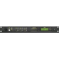
The Model MRT327 is a two-channel intercom station for use in RTS TW intercom systems. It may be used as a headset station or as a speaker station (with an optional MCS325 Modular Speaker). The MRT327 may be installed in optional console or rack mount configurations (see Figure 1-2).
1.1.2 FEATURES
Features of the MRT327 include:
- Call signaling: The MRT327 can send and receive 20 kHz call signals.
- Dual-Action Momentary/Latching Mic Switch: The Mic on/off switch can be used as a momentary push-to-talk switch or as a latching on/off switch.
- The MRT327 can receive 24 kHz "talk-off" signals for deactivation of the MRT327 microphone from a remote location.
- Microphone limiter: The microphone preamplifier circuit contains a limiter which helps to equalize output for different voice levels.
- Optional Microphone/Speaker and Headset Configurations: The standard MRT327 accepts an unbalanced, dynamic-mic headset or a dynamic microphone used in conjunction with an external speaker connected at the rear panel. It also has a jack for an optional Model MCP5 or MCP6 gooseneck panel microphone. Additionally, the MRT327 may be internally modified for use with a carbon or balanced-dynamic microphone. It can also be modified to provide the microphone audio as an unswitched, balanced output.
- Powering Options: The MRT327 receives operating power from the intercom line. It may be internally modified for local powering from a separate de power supply or batteries.
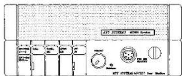
1.1.3 OPERATIONAL CONTROLS
See Figure 1-1.
CHANNEL 1-2: Selects either channel 1 or channel 2 for intercommunication.
CALL : Sends call signal to all stations on channel,
PANEL MIC: Selects microphone input from either the dynamic-mic headset connector or from the panel mic jack.
SPKR ON: Activates output to the rear panel speaker jack.
MIC ON: Turns the microphone on or off. The mic on/off LED is lit when the microphone is on.
VOLUME: Adjusts headphone/external speaker volume.
Sidetone: When an external speaker is used, this trimmer may be used to cancel acoustic feedback between the microphone and speaker. When a headset is used, this trimmer adjusts the level of the user's own voice in his or her headset.
1.1.4 CONNECTORS
1.1.4.1 Front Panel
DYN MIC HEADSET: Accepts a monaural, dynamic-microphone headset.
Panel Microphone: The MRT327 may be optionally fitted with a gooseneck panel microphone by pulling out the plug located in the upper-right corner of the front panel. The panel microphone jack accepts an optional RTS Model MCP5 (12-inch) or MCP6 (20-inch) gooseneck panel microphone.
1.1.4.2 Rear Panel
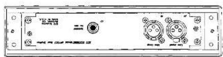
Line Input/ Line Loop : These are the intercom channel connectors. The connectors are parallel-wired for loop-through connection to additional stations.
Speaker: A 1/4-inch phone jack accepts an external speaker such as the Model MCS325 (8-ohms minimum).
1.1.5 INDICATORS
CALL: flashes for incoming call on currently selected channel.
MIC ON: Lights when microphone is switched on.
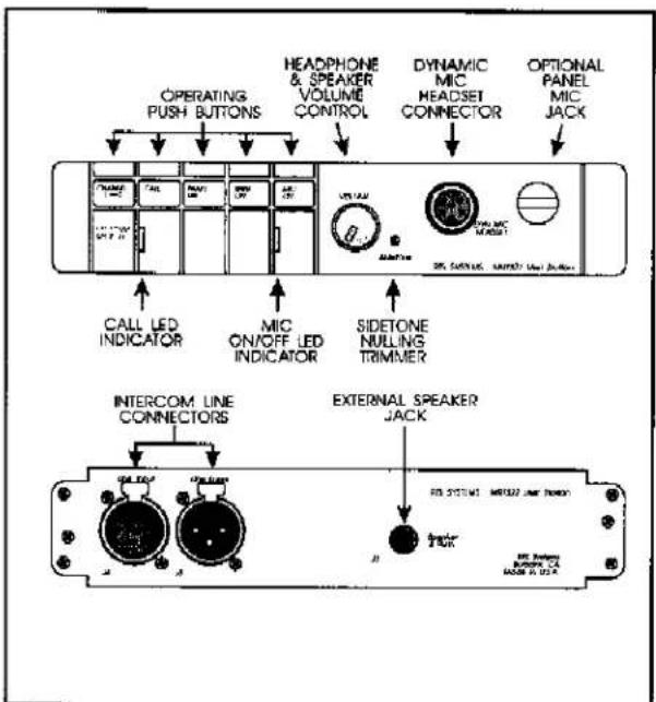
Figure 1-1 MRT327 Reference View
1.2 SPECIFICATIONS
1.2.1 GENERAL
Input DC Voltage
TW Mode: 18 to 35 volts DC
Local Power; 15 to 35 volts DC (12 to 15 volts DC, reduced performance)
DC Current Drawn from TW Line
Quiescent: 45 mA ±10%
Operating, 25-ohm phones: 75 mA ±10%
Operating, 25-ohm phones + call light: 90 mA ±10%
Operating, 8-ohm speaker: 240 mA ±10%
Operating, 8-ohm speaker + call light: 300 mA ±10%
Notes:
Operating current is measured with output level at 10 dB below clipping.
Local power option draws no current from TW line.
Impedance Across Line
10,000 ohms, minimum (designed for use with 200-ohm "TW" intercom lines)
Environmental Temperature
Operating: 0°C to 60°C
Storage: -40°C to 85°C
Humidity
Operating and Storage: 5% to 95%, non-condensing
Noise Contribution
(Ch 1): >-60 dBμ
(Ch 2): >-80 dBμ
1.2.2 MICROPHONE PREAMPLIFIER
Input Impedance
470 ohms ± 5% (dynamic mic)
Source Impedance
200 ohms, nominal
Maximum Input Level
150 millivolts
Frequency Response
(-54 dBu input): 100 Hz to 8 kHz ±3 dB
Limiter Range
30 dB
Carbon Mic Excitation Current
10 mA, nominal
1.2.3 CURRENT SOURCE
Transfer Ratio
3.3 mA/volt = 3.3 millisiemens
Output
±5 mA into 200 ohms = ±1 volt peak, nominal
1.2.4 SPEAKER AMPLIFIER
Maximum Voltage Gain
30 dB
Frequency Response
100 Hz to 8 kHz ±4 dB
Output Power
1.5 watts into 8 ohms nominal
Speaker DIM (speaker muting during mic activation)
adjustable, -4 to -30 dB (Factory set to -6 dB)
1.2.5 HEADPHONE AMPLIFIER
Voltage Gain
34 dB
Output Voltage
8 volts peak-to-peak into 25 ohms nominal
Output power
1/2 watt peak into 25 ohms
Frequency Response
150 Hz to 10 kHz ±3 dB
Headphone Impedance Range
25 to 600 ohms (600 to 2000 ohms with reduced levels)
Sidetone Adjustment Range
-20 dB to full on
1.2.6 CALL LIGHT
Signalling Frequency
20 kHz ±100 Hz
Flashing Rate
5 Hz ±2 Hz
1.2.7 TALK-OFF
Frequency
24 kHz nominal
1.2.8 CONNECTORS
Dynamic Microphone Headset
XLR type 6-pin female
Panel Microphone
1/4-inch standard phone jack, 3-circuit
Line Input
One (1) XLR type 3-pin female and one (1) XLR type
3-pin male, wired in parallel
1.2.9 MECHANICAL
Dimensions (Height x Width x Depth)
1.71" x 8.85" x 9.0" (44 mm x 224 mm x 228 mm)
Weight
2.75 pounds, 1.25 kilograms
Construction/Finish
Aluminum case, thermoplastic front panel, light gray finish
SPECIFICATION NOTES
0 dBm is a power level corresponding to 0.775 volts rms into 600 ohms (1 milliwatt)
dBu is a power level like dBm, but without the 600 ohm reference

A.
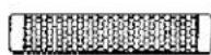
B.


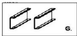

K.

L.


N.

0.
Main Components
A. MRT327 User Station
B. MCS325 Modular Speaker
Optional Components
C. MCP1 Rack Mount Kit (For Two Main Components)
D. MCP2 Rack Mount Kit (For Single Main Component)
E. MCP3 Console Mount Kit
F. MCP4 Tandem Mount Kit
G. MCP8 Side Channels (pair)
H. MCP7 Hand-Held Microphone w/6-pin connector
I. MCP6 Panel Mount Microphone 20"
J. MCP5 Panel Mount Microphone 12"
Most Common Package Configurations
K. Desk Top Headset Station, includes: MRT327 User Station (A) MCP8 Side Channels (G)
L. Console Mount Headset Station, includes MRT327 User Station (A)
MCP3 Console Mount Kit (E)
M. Portable Speaker Station, includes:
MRT327 User Station (A)
MCS325 Modular Speaker (B)
MCP4 Tandem Mount Kit (F)
MCP7 Hand-Held Microphone (H)
N. Rack Mount Speaker Station, includes:
MRT327 User Station (A)
MCS325 Modular Speaker (B)
MCP1 Rack Mount Kit (C)
MCP5 (J) or MCP6 (I) Panel Mic
O. Rack Mount Headset Station, includes: MRT327 User Station (A) MCP2 Rack Mount Kit (D)
Figure 1-2
Optional Components and Configurations
SECTION 2: INSTALLATION
2.1 USER-INSTALLED OPTIONS
To install options, the top cover of the MRT327 must be removed as shown in Figure 2-1. The following numbered paragraphs are keyed to the numbered items in Figure 2-2.
2.1.1 BALANCED MICROPHONE INPUT
The microphone input is factory configured for use with unbalanced type dynamic microphones. The input can be modified for use with balanced dynamic microphones.
- Cut traces W1 and W2 across T1 on the top side of the board.
- Install a 600:600 ohm, LM9003 type transformer (RTS part number 2306-0001-05) at T1 on the circuit board.
2.1.2 CARBON MICROPHONE INPUT
This procedure adds a carbon mic headset/handset jack to the back panel of the MRT327.
- Install resistors R6 (68 kohm), R7 (820 ohm) and R101 (100 ohm, 1/2 W).
- Install capacitors C4 (.033μF/50V mono) and C5 (.1 μF/50V mono).
- Install diode D1 (IN6263).
- Drill a 3/8-inch diameter hole on the rear panel, and install a Switchcraft number M114B phone jack (RTS part number 2013-0048-00).
- Wire phone jack as follows using 24 AWG wire:
Tip: to E1 on MRT327 board Ring: to E3 on MRT327 board Sleeve: to E2 on MRT327 board
2.1.3 UNSWITCHED MICROPHONE BALANCED (USMB) OUTPUT
This procedure adds an unbalanced microphone output to route the MRT327 microphone signal to external equipment. The output is taken before the microphone on/off switching circuitry.
- Install resistor R27 (220 ohm)
- Install capacitor C13 (22μF, 50V electrolytic)
- Install a 600:600 ohm, LM9003 type transformer (RTS part number 2306-0001-05) at T2 on the circuit board.
- Balanced output is obtained at pads E4 and E5 on the circuit board.
2.1.4 HEADPHONE GAIN BOOST
This modification raises the gain of the headphone amplifier from 26 dB to 34 dB for use with headphones that are outside the normal impedance range of 25 to 600 ohms.
- Install R42 (1.2 kohm)
- Install C30 (10 μF, 25V electrolytic).
2.1.5 LOCAL POWERING OPTION
This modification lets you use a separate power source to power the MRT327. This procedure can be used, for example, to power the MRT327 when wire resistance for long cable runs reduces the supply voltage from the intercom system below a usable level.
Use a dc power supply with a minimum output of +14 Vdc at 500 mA. Connect the positive side to pad E10. Connect negative side to either pad E11 or E12.
2.2 SPEAKER MUTING TRIMMER ADJUSTMENT
The speaker muting trimmer is accessible with the top cover removed. This trimmer adjusts the amount of speaker muting (also called speaker DIM) when the microphone is activated. Normally some amount of muting is required to prevent feedback between the microphone and speaker. Muting is factory preset at -6 dB. Turn trimmer R32 counterclockwise to increase speaker muting.
Note
If the MRT327 is always used as a speaker station and is not used with headphones, it may be possible to stop feedback using the Sidetone trimmer (accessible through the front panel) instead of removing the top cover and readjusting the speaker muting trimmer.

LIFT LEFT SIDE OF TOP COVER, AND SLIDE THE RIGHT SIDE BACK FAR ENOUGH TO CLEAR TAB ON FRONT PANEL BEFORE LIFTING UP.
Figure 2-1 Top Cover Removal

Figure 2-2 User-Installed Options / Speaker Muting Trimmer Location
2.3 MECHANICAL INSTALLATION
Dimensional requirements for the various mounting configurations are illustrated in Section 5 (See drawing number OD6916). Allow an additional 4.0 inches (102 mm) of rear panel clearance for connectors. The MRT327 has no special ventilation space requirements.
2.4 ELECTRICAL INSTALLATION
2.4.1 INTERCOM LINES, J4 AND J5
Intercom line connectors J4 and J5 are wired in parallel for loop-through connection to other intercom stations. Connector pin-outs are as follows:
Pin 1: Common (audio and DC)
Pin 2: CH 1/+DC input voltage
Pin 3: CH 2
2.4.2 EXTERNAL SPEAKER, J27
The SPEAKER OUTPUT jack provides an output for an external speaker (8 ohms minimum). The external speaker is connected using a 1/4-inch phone plug as follows;
Tip: Speaker high
Ring: Speaker low
Sleeve: No connection
2.4.3 HEADSET
Headphones should be 25-600 ohms. Lower impedance headphones are not recommended. Headphones with good acoustic isolation (20 to 40 dB) improve communication in high-noise environments and allow the user to listen at a less tiring, lower volume. The headset jack is wired as follows:
Pin 1: Balanced mic* low/unbalanced mic common
Pin 2: Balanced*/unbalanced mic high
Pin 3: Headphone/mic switch common
Pin 4: Headphone high
Pin 5: Headphone high
Pin 6: Mic switch high
*Balanced mic optional, see paragraph 2.1.1.
-
Tap the CHANNEL 1-2 button to select the desired channel.
-
Tap the PANEL MIC button once to select the optional panel mic jack (button in); tap it again to select the dynamic mic headset jack (button out).
-
The MIC ON button has two modes of operation:
a For push-to-talk operation, press and hold the button while talking. When you release the button the microphone will shut off.
b. For hands-free talk, tap the button once to turn on the microphone. Tap the button again to turn off the microphone.
The mic LED indicator lights when the mic is on.
- Tap the SPKR ON button once to activate the optional external speaker (button in). Tap it again to turn the speaker off (button out).
- Adjust the headphone / speaker listening level using the VOLUME control.
- The Sidetone trimmer may be used in either of two ways:
a. When using a headset, the Sidetone trimmer may be used to adjust the level of the user's own voice in the headphones. While speaking into the microphone, adjust the trimmer for the desired voice level.
b. When using an external speaker and a panel microphone instead of headset, the Sidetone trimmer may be used to minimize feedback between the speaker and the microphone. While talking into the microphone, adjust the trimmer to minimize the speaker output.
- To send a call signal, select the channel to be called, then press and hold the CALL button. The call LED will light while the button is pressed. When the called station responds, release the CALL button.
The call LED will flash when there is an incoming call signal on the currently selected channel. To respond, activate the microphone and begin talking.
SECTION 4: PARTS LISTS
4.1 WHERE TO OBTAIN PARTS
Telex Communications, Inc. 12000 Portland Avenue South Burnsville, MN 55337 U.S.A. Telephone: (877) 863-4169 Fax: (800) 323-0498
4.2 FINAL ASSEMBLY
Reference AS6593 Drawing in Section 5 for item numbers.
| FINAL ASSEMBLY | ||
| Item No. | Description | RTS Part No. |
| 1 | Front Panel Assy. Complete (See list below for breakdown.) | 9020659100 |
| 2 | Rear Panel Assy, Complete (See list below for breakdown.) | 9020659200 |
| 3 | Case Top/Bottom | 9060626000 |
| 4 | Printed Keycap. CALL | 9150669801 |
| 5 | Printed Keycap. PANEL MIC | 9150669802 |
| 6 | Printed Keycap. SPKR ON | 9150669803 |
| 7 | Printed Keycap. MIC ON | 9150669804 |
| 8 | Printed Keycap. CHANNEL 1-2 | 9150669805 |
| 9 | Switch Stem | 2705002100 |
| 10 | Volume Knob | 2703003700 |
| 11 | Case Screw | 9160630500 |
| 12 | Screw, Machine, CR PH. #4-40 x 3/8 | 51845039 |
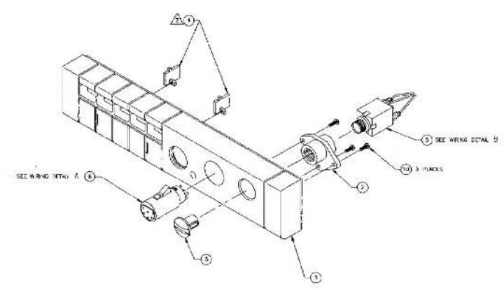
4.3 FRONT PANEL ASSEMBLY
Reference AS6591 Drawing in Section 5 for item numbers.
| FRONT PANEL ASSEMBLY | ||
| Item No. | Description | RTS Part No. |
| 1 | Bezel, Screened | 9070659100 |
| 2 | Bushing Adaptor | 9110627300 |
| 3 | Plug, Panel Microphone | 4501006300 |
| 4 | Lightpipe, Call Indicator | 4501006200 |
| 5 | Phone Jack With Metal Bushing (Panel Mic) | 2013004800 |
| 6 | Connector Insert, 6-pin Female (Dynamic Mic Headset) | 2018007700 |
PARTS LIST ABBREVIATIONS: CD, Ceramic Disk; CF, Carbon Film; CM, Ceramic Monolithic; EL, Electrolytic; LP, Denotes Local Purchase Item; MF, Metal Film; Rad, Radial Leads; Tant, Tantalum.
4.4 REAR PANEL ASSEMBLY
Reference AS6592 Drawing in Section 5 for item numbers.
| REAR PANEL ASSEMBLY | ||
| Item No. | Description | RTS Part No. |
| 1 | Rear Panel, Screened | 9080659200 |
| 2 | PC Board Assy. Complete (See list below for parts breakdown.) | 9030658000 |
| 3 | Screw, Machine, CR PH, #4-40 x 1/4 | 51845038 |
| 4 | Nut, Keps, #4-40 | 51745000 |
| 5 | Terminal | 43965P3 |
| 6 | Nut, Keps, #6-32 | 51745004 |
| 7 | Tubing | LP |
4.5 PC BOARD ASSEMBLY
| PC BOARD ASSEMBLY | ||
| Ref No. | Description | RTS Part No. |
| C1 | Capacitor, EL, Rad, 100 μF, 50V, 20% | 1513R1074I |
| C2 | Capacitor, EL, 10 μF, 25V | 1513R1064F |
| C6 | Capacitor, EL, 47 μF, 16V | 1513R4764E |
| C7, C8 | Capacitor, CM, 0.1 μF, 50V | 1511R1042I |
| C9 | Capacitor, EL, 10 μF, 25V | 1513R1064F |
| C10 | Capacitor, CD, 47 pF, 50V | 1510R4702I |
| C11 | Capacitor, CM, 0.1 μF, 50V | 1511R1042I |
| C12 | Capacitor, EL, 1 μF, 50V | 1513R1054I |
| C14 | Capacitor, CM, 0.22 μF, 50V | 1511R2242I |
| C15 - C17 | Capacitor, CM, 0.1 μF, 50V | 1511R1042I |
| C19 | Capacitor, CM, 0.1 μF, 50V | 1511R1042I |
| C20 | Capacitor, CD, 220 pF, 100V | 1510R8212R |
| C21 | Capacitor, EL, 1 μF, 50V | 1513R1054I |
| C22 | Capacitor, EL, 22 μF, 50V | 1513R2263I |
| C23 | Capacitor, CM, 0.1 μF, 50V | 1511R1042I |
| C24, C25 | Capacitor, EL, 10 μF, 25V | 1513R1064F |
| C26 | Capacitor, CD, 470 pF, 50v | 1510R4712I |
| C27, C28 | Capacitor, CM, 0.1 μF, 50V | 1511R1042I |
| C29 | Capacitor, EL, Rad, 220 μF, 16V, 20% | 1513R2274E |
| C31 | Capacitor, CM, 0.1 μF, 50V | 1511R1042I |
| C32 | Capacitor, EL, Rad, 100 μF, 50V, 20% | 1513R1074I |
| C34 | Capacitor, CM, 0.1 μF, 50V | 1511R1042I |
| C35 | Capacitor, CD, 470 pF, 50v | 1510R4712I |
| C36 | Capacitor, CD, 10 pF, 500V | 1510R1002I |
| C36 | Capacitor, CD, 100pF, 50V | 1510R1012I |
| C37 | Capacitor, CM, 0.1 μF, 50V | 1511R1042I |
| C38 | Capacitor, EL, 47 μF, 16V | 1513R4764E |
| C39 | Capacitor, EL, 22 μF, 50V | 1513R2263I |
| C40 | Capacitor, CM, 0.1 μF, 50V | 1511R1042I |
| C41, C42 | Capacitor, EL, Rad, 100 μF, 50V, 20% | 1513R1074I |
| C43 | Capacitor, EL, 22 μF, 50V | 1513R2263I |
| C44 | Capacitor, EL, 22 μF, 50V | 1513R2263I |
| C45 | Capacitor, EL, 1000 μF, 16V | 1513R1084E |
| C46 | Capacitor, EL, 10 μF, 25V | 1513R1064F |
| C47 | Capacitor, CM, 0.1 μF, 50V | 1511R1042I |
| C48 | Capacitor, EL, 4700 μF, 25V | 1513R4784F |
| C49 | Capacitor, EL, Rad, 100 μF, 50V, 20% | 1513R1074I |
| C50 | Capacitor, CD, 0.1 μF, 500V | 1510R1042Q |
| C51 | Capacitor, EL, 1 μF, 50V | 1513R1054I |
| C51 | Capacitor, EL, 1 μF, 50V | 1513R1054I |
| C52 | Capacitor, CM, 0.1 μF, 50V | 1511R1042I |
| C53 | Capacitor, EL, 1 μF, 50V | 1513R1054I |
| C54 | Capacitor, CM, 0.1 μF, 50V | 1511R1042I |
| C55 | Capacitor, EL, 22 μF, 50V | 1513R2263I |
| C56 | Capacitor, NPO Mono, 0.0033 μF, 50V | 1511R3321I |
| C57 | Capacitor, Mylar, 0.047 μF, 100V | 1514R4732L |
| C58 | Capacitor, CM, 0.1 μF, 50V | 1511R1042I |
| C59 | Capacitor, CD, 100pF, 50V | 1510R1012I |
| C60 | Capacitor, CM, 0.1 μF, 50V | 1511R1042I |
| C61 | Capacitor, NPO Mono, 0.0033 μF, 50V | 1511R3321I |
| C62 | Capacitor, Mylar, 0.047 μF, 100V | 1514R4732L |
| C63 | Capacitor, CM, 0.1 μF, 50V | 1511R1042I |
| C64 | Capacitor, CD, 100pF, 50V | 1510R1012I |
| C66 | Capacitor, CD, 47 pF, 50V | 1510R4702I |
| C67 | Capacitor, EL, 1 μF, 50V | 1513R1054I |
| C68, C69 | Capacitor, CM, 0.1 μF, 50V | 1511R1042I |
| C70 | Capacitor, CM, 0.001 μF, 50V | 1511R1022I |
| C71 | Capacitor, CM, 0.01 μF, 50V | 1511R1032I |
| C72 | Capacitor, EL, 47 μF, 16V | 1513R4764E |
| D2 - D4 | Diode, 1N914B | 160109140B |
| D5 - D9 | Diode, 1N4004, 1A, 400V | 1601400400 |
| D10 | Diode, 1N914B | 160109140B |
| D11, D12 | Diode, 1N4004, 1A, 400V | 1601400400 |
| D13 | Diode, 1N5245B Zener, Voltage Reg 15V | 160152450B |
| D14 | Diode, 1N5365B Zener, Voltage Reg 36V | 160153650B |
| D15, D16 | Diode, 1N4004, 1A, 400V | 1601400400 |
| D17 - D20 | Diode, 1N914B | 160109140B |
| D21 | Diode, 1N4004, 1A, 400V | 1601400400 |
| D23 - D28 | Diode, 1N914B | 160109140B |
| DS1, DS2 | LED, Red, Striking Bright, AND 180GRP | 1801002700 |
| FB1-FB8 | #73 Shield Bead | 2404000100 |
| J1 | Connector, Top Entry, 3-Pin Male | 2007013900 |
| J2 | Connector, Top Entry, 6-Pin Male | 2007013800 |
PARTS LIST ABBREVIATIONS; CD, Ceramic Disk; CF, Carbon Film; CM, Ceramic Monolithic; EL, Electrolytic; MF, Metal Film; Rad, Radial Leads; Tant, Tantalum.
| PC BOARD ASSEMBLY | ||
| Ref No. | Description | RTS Part No. |
| J3 | Jack, PC Mt, 3/8" H | 2013004900 |
| J4 | Connector, PC Mt, 3-Pin Male, NC3MDH | 2018001000 |
| J5 | Connector, PC Mt, 3-Pin Female, NC3FDH | 2018001100 |
| Q1 | Transistor, J305 | 1602030500 |
| Q2 | Transistor, 2N5210 | 1602521000 |
| Q3 | Transistor, J305 | 1602030500 |
| Q4, Q5 | Transistor, 2N5087 | 1602508700 |
| Q6 | Transistor, 2N5460 | 1602546000 |
| Q7 | Transistor, 2N5210 | 1602521000 |
| R1 | Resistor, CF, 1K Ohm, 1/4W, 5% | 140210015D |
| R2 | Resistor, CF, 2K Ohm, 1/4W, 5% | 140220015D |
| R3 | Resistor, CF, 100 Ohm, 1/4W, 5% | 52154305 |
| R4 | Resistor, CF, 470 Ohm, 1/4W, 5% | 140247005D |
| R5 | Resistor, CF, 200 Ohm, 1/4W, 5% | 140220005D |
| R8 | Resistor, CF, 470 Ohm, 1/4W, 5% | 140247005D |
| R9, R10 | Resistor, CF, 22K Ohm, 1/4W, 5% | 140222025D |
| R11, R12 | Resistor, CF, 470 Ohm, 1/4W, 5% | 140247005D |
| R13 | Resistor, CF, 22K Ohm, 1/4W, 5% | 140222025D |
| R14 | Resistor, CF, 10K Ohm, 1/4W, 5% | 140210025D |
| R15 | Resistor, CF, 5.1M Ohm, 1/4W, 5% | 140251045D |
| R16 | Resistor, CF, 22K Ohm, 1/4W, 5% | 140222025D |
| R17, R18 | Resistor, CF, 5.1M Ohm, 1/4W, 5% | 140251045D |
| R19 | Resistor, CF, 100K Ohm, 1/4W, 5% | 140210035D |
| R20 | Resistor, CF, 200 Ohm, 1/4W, 5% | 140220005D |
| R21 | Resistor, CF, 22K Ohm, 1/4W, 5% | 140222025D |
| R22, R23 | Resistor, CF, 100K Ohm, 1/4W, 5% | 140210035D |
| R24 | Resistor, CF, 220K Ohm, 1/4W, 5% | 140222035D |
| R25 | Resistor, CF, 15K Ohm, 1/4W, 5% | 140215025D |
| R26 | Resistor, CF, 10K Ohm, 1/4W, 5% | 140210025D |
| R28 | Resistor, CF, 180K Ohm, 1/4W, 5% | 140218035D |
| R29 | Resistor, CF, 220K Ohm, 1/4W, 5% | 140222035D |
| R30 | Trimpot, 10K Audio, Right Angle | 1406004400 |
| R31 | Resistor, CF, 22K Ohm, 1/4W, 5% | 140222025D |
| R32 | Trimpot, 100K | 1409001800 |
| R33 | Resistor, CF, 10K Ohm, 1/4W, 5% | 140210025D |
| R34 | Resistor, CF, 100K Ohm, 1/4W, 5% | 140210035D |
| R35 | Resistor, CF, 22K Ohm, 1/4W, 5% | 140222025D |
| R36 | Resistor, CF, 100K Ohm, 1/4W, 5% | 140210035D |
| R37 | Resistor, CF, 100 Ohm, 5%, 1/4W | 140210005D |
| R38 | Resistor, CF, 100K Ohm, 1/4W, 5% | 140210035D |
| R39 | Resistor, CF, 100 Ohm, 5%, 1/4W | 140210005D |
| R40 | Resistor, CF, 2.7 Ohm, 1/4W, 5% | 14022R705D |
| R41 | Resistor, CF, 22K Ohm, 1/4W, 5% | 140222025D |
| R43 | Resistor, CF, 2.7 Ohm, 1/4W, 5% | 14022R705D |
| R44 | Resistor, CF, 22K Ohm, 1/4W, 5% | 140222025D |
| R45 | Resistor, CF, 10 Ohm, 1/2W, 5% | 140210R05E |
| R46 | Resistor, CF, 22K Ohm, 1/4W, 5% | 140222025D |
| R47 | Resistor, CF, 10K Ohm, 1/4W, 5% | 140210025D |
| R48 | Resistor, CF, 22 Ohm, 1/4W, 5% | 140222R05D |
| R50,R51 | Resistor, CF, 22K Ohm, 1/4W, 5% | 140222025D |
| R52 | Trimpot, 10K Ohm Linear, Horiz | 1409006000 |
| R53,R54 | Resistor, MF, 60.4K, 1/4W, 1% | 140360422D |
| R55 | Resistor, CF, 22 Ohm, 1/4W, 5% | 140222R05D |
| R56,R57 | Resistor, MF, 20.0K, 1/4W, 1% | 140320022D |
| R58 | Resistor, CF, 100 Ohm, 5%, 1/4W | 140210005D |
| R59 - R61 | Resistor, CF, 100K Ohm, 1/4W, 5% | 140210035D |
| R62 | Resistor, CF, 10K Ohm, 1/4W, 5% | 140210025D |
| R63,R64 | Resistor, CF, 220K Ohm, 1/4W, 5% | 140222035D |
| R65 | Resistor, CF, 200 Ohm, 1/4W, 5% | 140220005D |
| R66 | Resistor, CF, 620 Ohm, 1/4W, 5% | 140262005D |
| R67 | Resistor, CF, 10 Ohm, 1/2W, 5% | 140210R05E |
| R68 | Resistor, MF, 301 Ohm, 1/4W, 1% | 140330102D |
| R69 | Resistor, MF, 3.01K, 1/4W, 1% | 140330112D |
| R70 | Resistor, CF, 1K Ohm, 1/4W, 5% | 140210015D |
| R71 | Resistor, MF, 3.3 Ohm, 1/8W, 1% | 14023R305B |
| R72 - R74 | Resistor, CF, 10K Ohm, 1/4W, 5% | 140210025D |
| R75 | Resistor, CF, 1K Ohm, 1/4W, 5% | 140210015D |
| R76 | Resistor, CF, 270K Ohm, 1/4W, 5% | 140227035D |
| R77 | Resistor, CF, 100K Ohm, 1/4W, 5% | 140210035D |
| R78 | Resistor, CF, 10K Ohm, 1/4W, 5% | 140210025D |
| R79 | Resistor, CF, 1K Ohm, 1/4W, 5% | 140210015D |
| R80 | Resistor, CF, 47K Ohm, 1/4W, 5% | 140247025D |
| R81 | Resistor, CF, 470K, 1/4W, 5% | 140247035D |
| R82 | Resistor, MF, 10.5K, 1/8W, 1% | 140310522D |
| R83 | Trim Pot, Cermet, 5K | 1409006600 |
| R84 | Resistor, CF, 2.2M Ohm, 1/4W, 5% | 140220045D |
| R85 | Resistor, CF, 470K, 1/4W, 5% | 140247035D |
| R86 | Resistor, CF, 150 Ohm, 1/4W, 5% | 140215005D |
| R87 | Resistor, CF, 10K Ohm, 1/4W, 5% | 140210025D |
| R88 | Resistor, CF, 47K Ohm, 1/4W, 5% | 140247025D |
| R89 | Resistor, MF, 8.25K, 1/4W, 1% | 140222045D |
| R90 | Trim Pot, Cermet, 5K | 1409006600 |
| R91 | Resistor, CF, 470K, 1/4W, 5% | 140247035D |
| R92 | Resistor, CF, 22K Ohm, 1/4W, 5% | 140222025D |
| R93 | Resistor, CF, 1M Ohm, 1/8W, 5% | 140210045D |
| R94,R95 | Resistor, CF, 51K Ohm, 1/4W, 5% | 140251025D |
| R96 | Resistor, CF, 100K Ohm, 1/4W, 5% | 140210035D |
| R97 | Resistor, CF, 180K Ohm, 1/4W, 5% | 140218035D |
| PC BOARD ASSEMBLY | ||
| Ref No. | Description | RTS Part No. |
| R98 | Resistor, CF, 100 Ohm, 5%, 1/4W | 140210005D |
| R99 | Resistor, CF, 1M Ohm, 1/8W, 5% | 140210045D |
| R100 | Resistor, CF, 220K Ohm, 1/4W, 5% | 140222035D |
| R102 | Resistor, CF, 1M Ohm, 1/8W, 5% | 140210045D |
| R103 | Resistor, CF, 150 Ohm, 1/4W, 5% | 140215005D |
| R104 | Resistor, CF, 100K Ohm, 1/4W, 5% | 140210035D |
| R105 | Resistor, CF, 1K Ohm, 1/4W, 5% | 140210015D |
| S1-S3 | Switch, Push Button, Alternate Action | 1911004600 |
| S4, S5 | Switch, Push Button, Momentary | 1911004700 |
| U1 | IC, Analog Switch, CD4053BE | 16034053BE |
| U2 | IC, LM833 | 1603083300 |
| U3 | IC, Amp, SGS TBA820M | 160308200M |
| U4 | IC, Op Amp, National LM386N-1 | 1603038600 |
| U5 | IC, MC34072D | 1603014300 |
| U6 | IC, Analog Switch, CD4053BE | 16034053BE |
| U7 | IC, Voltage Regulator, LP2950C2-5 | 1603014100 |
| U8 | IC, Voltage Regulator, National LM317T | 160303170T |
| U9 | IC, 4093B, Quad 2-input NAND | 160340930B |
| U10, U11 | IC, Tone Decoder, XR-L567 | 1603014200 |
| U12 | IC, 14001B | 160314001B |
| U13 | IC, 4013 | 160314001B |
| XDS1, XDS2 | 90-Degree LED Mount, Bivar T-1.75 | 1801002800 |
| XU1 | Socket, 16-Pin DIP | 2001000300 |
| XU2-XU5 | IC Socket, 8-Pin | 2001000100 |
| XU6 | Socket, 16-Pin DIP | 2001000300 |
| XU9 | IC Socket, 14-Pin | 2001000200 |
| XU10, XU11 | IC Socket, 8-Pin | 2001000100 |
| XU12, XU13 | IC Socket, 14-Pin | 2001000200 |
| Y1 | Crystal, 40 kHz | 3301001000 |
| Nut, Hex, #4-40 (Qty 1) | 1007002500 | |
| Washer, Compression, #4-40 (Qty 1) | 1006004100 | |
| Heatsink, Aham 361 (Qty 1) | 4502000700 | |
| Screw, #2-56 x 3/16, PH Phtl (Qty 2) | 1008200900 | |
| Screw, #4-40 x .375 (Qty 1) | 1008400300 | |
| Washer, Nylon, #4 (Qty 2) | 1008005300 | |
9030658000, B
SECTION 5: DRAWINGS
(Arranged in alphabetical order)
| Drawing Number | Title |
| AS6580 | PC Board Assembly |
| AS6591 | Front Panel Assembly |
| AS6592 | Rear Panel Assembly |
| AS6593 | Final Assembly |
| BD6593 | Block Diagram, MRT327 |
| OD6916 | Outline and Dimension Drawings (4 sheets) |
| PD6593 | Packaging Drawing |
| SD6580 | Schematic Diagram (2 sheets) |

| REVISIONS | ||||
| ZONE REV | DESCRIPTION | DATE | APPROVED | |
| A | REV AND REdrawn TO COMPLY WITH ARTWORK CHANGES.RKS | 5/29/90 | ||
| B | ACDED NOTE 4 PER ECO#3226.RCS | 10/9/90 | ||
| C | CHG. VIEW OF ASSEMBLY TO REFLECT REV E ARTWORK. | 13 MAY .94 | WK | |
SEE SEPARATE PARTS LIST 9030-6580-00
| INSTALL GROUND TEST POINT (SND TP) 3.12 ABOVE PCB SURFACE. APPLY TORQUE UNTL COMPRESSION WASHER COMPRESSES TO FAFL ITS ORGANAL HEIGHT. ANY HOLE NOT BEING USED (OPT PARTS, TEST POINTS, AND E ROLES) SHOULD BE MASKED SE WOLED SO DRING. APPLY GUPTOL OR EQUIV. TO TRM POIS R53 AND SIO AFTER THEY ARE SET PER TEST PROCEDURE. DO NOT APPLY ADHESIVE TO TRIMERS R52 AND R52. | UNLESS COUNDED SYSTEMS
DRAWN NO.### & ### APP REF.###
## ## ## ## ## ## ## ## ## ## ## ## ## ## ## ## ## ## ## ## ## ## ## ## ## ## ## ## ## ## ## ## ## ## ## ## ## ## ## ## ## ## ## ## ## ## ## ## ## ## ## ## ## ## ## ## ## ## ## ## ## ## ## ## ## ## ## ## ## ## ## ## ## ## ## ## ## ## ## ## ## ## ## ## ## ## ## ## ## ## ## ## ## ## ## ## ## ## ## ## # | ||||||
| APPROALS DATE | |||||||
| DRAWN R.K.BOOTS 5/29/90 | |||||||
| CHECKED | |||||||
| SIZE FLOW HD. DWD HD. AS6580 | |||||||
| SCALE =1/4 AS65801 | |||||||
NOTES:
1. INSTALL SHUND TEXT POINT (OND TR) 3.12 ABOVE
INSTALL GROUN
PCD SURFACE
FGB 304-002.
(2.) APPLY TORQUE UNTL COMPRESSION WASHER COMPRESSES
TO HALF ITS ORIGINAL HEIGHT.
3. ANY HOLE NOT BEING USED (OPT PARTS, TEST POINTS, AND E
NOLES) SHOULD BE MASKED BEFORE WAVE SO.DERING
(4.) APPLY GLYPTOL, OR EOUN., TO TRIM POTS RE3 AND RSD AFTER
THEY ARE SET PER TEST PROCEDURE, DO NOT APPLY ACRESME
C TRIMMERS RS2 AND \$32.
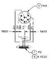
FRECE DUTLA
WRES ARE 28MG,
STRANZED VRY. (9' 10)

WRES.0711 B
WRES ARE 2840G.
SHAKED VX (5" UG)
SEE SEPARATE PARTS LIST 9020-6591-00
| 1 | SHRINK SLEEVE MIRE CONNECTIONS TO ITEMS 5 AND 6 (2 PLACES). |
| 2 | INSTALL LIGHTPipes (ITEM 4) THEN APPLY SOLDERING IRCH TO THE PROKUNDING GUIDE PING TO SET LIGHTPipes PERWANONLY IN PLACE. |
| ORDER BY: 2014-03-20 | DESCRIPTION NO.: | RFS SYSTEMS, NC DRAWING, OUTRUNS | ||||||||
| ITEMS BY: 2014-03-20 | APPROVAL NAME: | DATE: | ASSEMBLY DRAWING-FRONT PANEL, BRT327 | |||||||
| DRAWN BY: | XXX | ### | ||||||||
| CHECKED BY: | SPECIALTY: | SCALE: | ||||||||
| SHEET ID: | STRAWB: | R. COROLY: | ||||||||
| DWG BY: | SPECIALTY: | S. CHI: | ||||||||
| MARKS BY: | REV. NO.: DJ6C572 AS659* | REV. NO.: DJ6C572 AS659* | ||||||||
| ISO Date: 2014-03-20 | SPECIALTY: | AUSTO DATE: 2014-03-20 | SHEET 1 OF 1 | |||||||
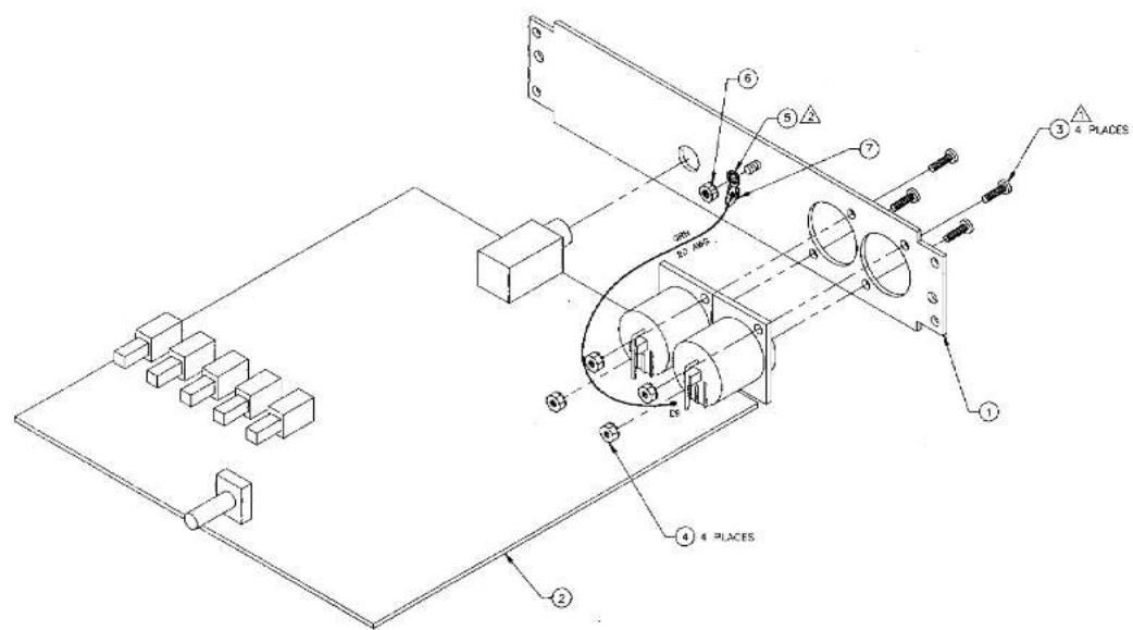
SEE SEPARATE PARTS LIST 9020-6592-00
△ APPLY ACHESME COMPOUND (LOGITE 425/TELEX JM328) TO THREADS OF SCRENS (ITEM 3) TO PREVENT NUTS FROM GETTING LOOSE.
2 SOLDER LUG (ITEM 5) MUST NOT COVE IN CONTACT WITH HEATSINK OF UB ON CIRCUIT BOARD.
NOTES: UNLESS OTHERWISE SPECIFIED
| UNLESS OTHERWISE SPECIFIED | COMPACT NO. | RTS SYSTEMSBURNY, CALIFICA USAASSEMBLY DRAWING-REAR PANEL,MODEL MRT327 | |||||
| RISKI: U.S. KAFIR & WELD ROOT ROOTSAND SUSTAINING ITEMS | |||||||
| INFORMATION AS IN PARTS | APPROVALS | DATE | |||||
| TOMATO: NO. | ORDER NAME: 4.000-01.000-AUG-02 | DRAWN: R.T.CRUG | 5/2/92 | ||||
| MATERIAL | CHECKEDS: M | 5/25/90 | |||||
| —— | ISSUED | ||||||
| NEXT ASSY | USED ON | TIME: —— —— | SHEET NO.NO:C160572 | DWG NO.AS8592 | REV.A | ||
| APPLICATION | SCALE 1/1 | AS33201/DWG | SHEET 1 OF 1 | ||||
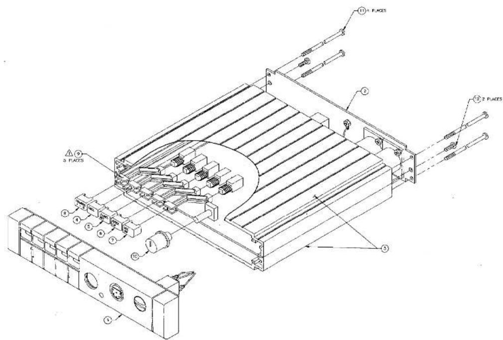
SEE SEPARATE PARTS LIS® 9010-6593-00
PUSH SWITCH STEM (ITEM 5) ONTO SWITCH UNI. IT LOCKS (5 PLACES)
NOTES: UNLESS OTHERWISE SPECIFIED
| ORDER BY: | DESCRIPTION: | RTS SYSTEMS NC WASHING CAPSIBLE NO. | |||||
| ITEMS NAME: | APPROVALS | DATE | |||||
| DRAWN BY:### ### ### ### ### | ### | RICHMONS | FINAL ASSEMBLY- MODEL MRT327 | ||||
| ISO### | CHECKED BY:### | ### | |||||
| REV### | ### | ||||||
| NOT APPI: USED BY:### | DRAWN | ### | ### | ### | |||
| APPLICATION: | TITLE | DJB05721 AS6593 | 100 | ||||
![graph TD A["Panel NO: LCK"] --> B["ON/O N C"] B --> C["CMC GATE"] C --> D["MC PREQAP (40dB MAX)"] D --> E["MC ON-DIFF CADS GATE"] E --> F["CLK BUFFER"] F --> G["CURRENT BLUT"] G --> H["LEFT SWITCH"] H --> I["POWER DOWN LINE TERM SWITCH"] I --> J["CH SELECT CADS GATE"] J --> K["SOFT ON SWITCH"] K -->…](/content/2026/05/980372/images/288eed39c245d9c3c231826a024c182a010a754be57a1cd41aedcb60f5066c5b.jpg)
| DATE: 01/24/2023 | DATE: 01/24/2023 | ||||
| APPROVED BY: N. NO. | APPROVED BY: N. NO. | ||||
| SHEET NAME: 01/24/2023 | SHEET NAME: N. NO. | ||||
| DATE: 01/24/2023 | DATE: 01/24/2023 | ||||
| APPROVED BY: N. NO. | APPROVED BY: N. NO. | ||||
| DATE: 01/24/2023 | DATE: 01/24/2023 |

| REV/REV | ||||
| 2016 | REV | LEXCH MCH | DATE | APPROVED |


| APPLICATIATION | APPLICATIATION | RDS SYSTEMS | |||
| DATE: 2017-03-28 | ORDER BY: 2017-03-28 | ||||
| APPROVALS | DATE | OUTLINE DRAWING-RACK MOUNT SPEAKERSTATION, MCS325/MRT327 | |||
| DRAWN BY: 2017-03-28 | CHECKED BY: 2017-03-28 | ||||
| DRAWN BY: 2017-03-28 | CHECKED BY: 2017-03-28 | ||||
| HOT AID | USED ON | CHECKED BY: 2017-03-28 | CHECKED BY: 2017-03-28 | D6B0572 | C6D916 |
| APPLICATION | SOLDEN BY: 2017-03-28 | SHEET 1 OF 4 | |||


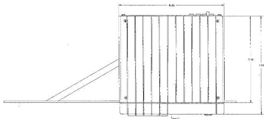


| DATE: 2016-04-20 | CONTACT NO. | RTS SYSTEMS | |||||
| APPROVED BY: 380000000000000000000000000000000000000000000000000000000000000000000000000000000000000000000000000000 | |||||||
| APPROVED | DATE | OUTLINE DRAWING-RACK MOUNT HEADSET | |||||
| ORDER | R.T.C.R.E. | 11/29/2016 | |||||
| CHECKED | ### | ### | |||||
| NOT ASSY | USED ON | PREF | ORDER | ITEMS FROM NO. D#G 5072 | REV. | ||
| DWG NO. CD6916 | |||||||
| APPLICATION | SCALE: V/H | DESCRIPTION: ### | |||||
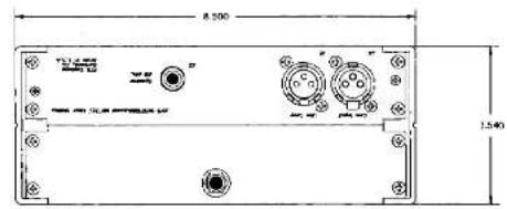

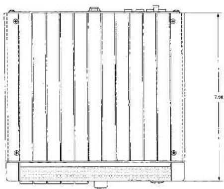

| NOT APPT. | USED ON | 170N | DATE: 11/18/30 | RTS SYSTEMS | ||||||
| APPROALS | DATE | |||||||||
| 2/18 | 2/18 | 2/18 | DRAWN, S. D. | 11/18/30 | OUTLINE DRAWING-TABLE-TOP SPEAKERSTATION, MCS325/MRT327 | |||||
| CHECKED | 1/2-1/16 | |||||||||
| APPROL | DATE: 11/04/29 | TWO NO.1605721 | CD8916 | |||||||
| APPLICATION | SCALE: 1/4 | |||||||||


| REV.01% | ||||
| 2018 | REV | DISCR.PROK | DATE | APPROVED |
| APPROVED BY: | CONTROL NO.: | RITS SYSTEMS | |||||
| VEGET DREAMS, OILSAGE | APPROVED | DATE | OUTLINE DRAWING -WEDDL MRT237CONSOLI WOUNT OPTION | ||||
| SHORT CREAM | 10510 CM | PANO | STOCK | DATE | |||
| APPROVED BY: | PANO | DATE | SHEET 4" A | ||||


Packaging Drawing, Model MRT327 Sheet 1 of 1
| DATE: 01/02/2015 | DATE: 01/02/2016 | RPG SYSTEMS | ||||
| AP-10000000000000000000000000000000000000000000000000000000000000000000000000000000000000000000000000000 | AP-100000000000000000000000000000000000000000000000000000000000000000000000000000000000000000000000 | PACAGA G DRANDING--MODEL MR 327 | ||||
| AP-100000000000000000000000000000000000000000000000000000000000000000000000000000000000000000000000 | ||||||
| DATE: 01/02/2015 | DATE: 01/02/2016 | DATE: 01/02/2017 | ||||
| AP-100000000000000000000000000000000000000000000000000000000000000000000000000000000000000000000 | AP-101111111111111111111111111111111111111111111111111111111111111111111111111111111111111111111111111111 | PACAGA G DRANDING--MODEL MR 327 | ||||


ON OIS AND RED AIR IS NOT INSTALLED ON THE SCHO
01 BREAKER OBL. NOET AS FOLLOWS TEN NO ORNTER SURVEGET TO IMPROVE YOU
- OFFICIAL "H (HEAVENED) GAIN BOOST" PARTS 030842
- AIE POT INSTALLED OR STANDARD APPURANCE INSTALLATION RACES OR CASH FROM 2014 TO 31 May
- OPTION: 2-008 (PROCESSED LIME LEVEL)
(OUTPUT-BALAMO) CIRCUIT PARTS 2.3.12 (800MM/600MM) ARE NOT INSTALLED ON STANDARDS
□
-
OPTIONAL "CARDON MICROPHONE" CIRCUIT PARTS R&D CART & ON ARE NOT INSTALLED ON STANDAY ASSOCULIES
-
OPTIONAL BALANCED MICROPHONE INPUT CINGUIT PART,
AXEEMILTEC
-
ON VALUES ARE WITH MICROPARAS/VOLTS.
-
RESISTORS ARE SHOWN IN CHAS
-
ALL RESISTORS ARE CABBEN TEL/4897-08
NOTES: IN THE CONTENTS PROTECTED
| CONTACT NO. | RTS SYSTEMS | ||
| Dram RHOULSON Checked | SCHEDULED DIAGRAM MPT327, WOLLAR USER STATUM | ||
| Arrived | SIZE FJ50 D 16C572. SD4580 | ||
- COPYRIGHT NOTICE
- WARRANTY NOTICE
- CUSTOMER SUPPORT
- RETURN SHIPPING INSTRUCTIONS
- SHIPPING TO THE MANUFACTURER
- TABLE OF CONTENTS
- SECTION 1: DESCRIPTION AND SPECIFICATIONS ..... 1-1
- SECTION 2: INSTALLATION 2-1
- 1.1.2 FEATURES
- 1.1.3 OPERATIONAL CONTROLS
- 1.1.4 CONNECTORS
- 1.1.4.1 FRONT PANEL
- 1.1.4.2 REAR PANEL
- 1.1.5 INDICATORS
- 1.2 SPECIFICATIONS
- 1.2.1 GENERAL
- 1.2.2 MICROPHONE PREAMPLIFIER
- 1.2.3 CURRENT SOURCE
- 1.2.4 SPEAKER AMPLIFIER
- 1.2.5 HEADPHONE AMPLIFIER
- 1.2.6 CALL LIGHT
- 1.2.7 TALK-OFF
- 1.2.8 CONNECTORS
- 1.2.9 MECHANICAL
- SPECIFICATION NOTES
- MAIN COMPONENTS
- OPTIONAL COMPONENTS
- MOST COMMON PACKAGE CONFIGURATIONS
- SECTION 2: INSTALLATION
- 2.1 USER-INSTALLED OPTIONS
- 2.1.1 BALANCED MICROPHONE INPUT
- 2.1.2 CARBON MICROPHONE INPUT
- 2.1.3 UNSWITCHED MICROPHONE BALANCED (USMB) OUTPUT
- 2.1.4 HEADPHONE GAIN BOOST
- 2.1.5 LOCAL POWERING OPTION
- 2.2 SPEAKER MUTING TRIMMER ADJUSTMENT
- NOTE
- 2.3 MECHANICAL INSTALLATION
- 2.4 ELECTRICAL INSTALLATION
- 2.4.1 INTERCOM LINES, J4 AND J5
- 2.4.2 EXTERNAL SPEAKER, J27
- 2.4.3 HEADSET
- SECTION 4: PARTS LISTS
- 4.1 WHERE TO OBTAIN PARTS
- 4.2 FINAL ASSEMBLY
- 4.3 FRONT PANEL ASSEMBLY
- 4.4 REAR PANEL ASSEMBLY
- 4.5 PC BOARD ASSEMBLY
Brand : RTS
Model : MRT-327
Category : Intercom