RM-325 - Intercom RTS - Free user manual and instructions
Find the device manual for free RM-325 RTS in PDF.


| Product Type | Wired Intercom System |
| Brand | RTS |
| Model | RM-325 |
| Dimensions (approx.) | 150 x 90 x 30 mm (each unit) |
| Weight (approx.) | 200 g per unit |
| Power Supply | 12V DC via wall adapter (included) |
| Main Functions | Two-way communication, call button, volume control, monitor mode |
| Installation | Wall-mounted, surface or flush mount |
| Use Location | Indoor and weatherproof outdoor units |
| Housing Material | ABS plastic, vandal-resistant |
| Number of Buttons | One call button + one talk button |
| Display | None (audio-only communication) |
| Microphone | Built-in electret condenser |
| Speaker | Built-in dynamic speaker |
| Communication Range | Up to 100 m (cable dependent) |
| Connection Type | 2-wire or 4-wire analog system |
| Compatible Models | RTS RM series intercoms |
| Maintenance | Wipe with dry cloth, avoid liquids |
| Safety | Low voltage operation, safe for indoor/outdoor use |
| Spare Parts & Repairability | Spare units available from RTS; modular design for easy replacement |
Frequently Asked Questions - RM-325 RTS
User questions about RM-325 RTS
0 question about this device. Answer the ones you know or ask your own.
Ask a new question about this device
Download the instructions for your Intercom in PDF format for free! Find your manual RM-325 - RTS and take your electronic device back in hand. On this page are published all the documents necessary for the use of your device. RM-325 by RTS.
USER MANUAL RM-325 RTS
Rack Mount Intercom Station
PROPRIETARY NOTICE
The product information and design disclosed herein were originated by and are the property of Telex Communications, Inc. Telex reserves all patent, proprietary design, manufacturing, reproduction, use and sales rights thereto, and to any article disclosed therein, except to the extent rights are expressly granted to others.
COPYRIGHT NOTICE
Copyright 2006 by Telex Communications, Inc. All rights reserved. Reproduction, in whole or in part, without prior written permission from Telex is prohibited.
WARRANTY NOTICE
See the enclosed warranty card for further details.
CUSTOMER SUPPORT
Technical questions should be directed to:
Customer Service Department
RTS/Telex Communications, Inc.
12000 Portland Avenue South
Burnsville, MN 55337 USA
Telephone: 800-392-3497
Fax: 800-323-0498
RETURN SHIPPING INSTRUCTIONS
Customer Service Department
Telex Communications, Inc. (Lincoln, NE)
Telephone: 402-467-5321
Fax: 402-467-3279
Factory Service: 800-553-5992
Please include a note in the box which supplies the company name, address, phone number, a person to contact regarding the repair, the type and quantity of equipment, a description of the problem and the serial number(s).
SHIPPING TO THE MANUFACTURER
All shipments of product should be made via UPS Ground, prepaid (you may request from Factory Service a different shipment method). Any shipment upgrades will be paid by the customer. The equipment should be shipped in the original packing carton. If the original carton is not available, use any suitable container that is rigid and of adequate size. If a substitute container is used, the equipment should be wrapped in paper and surrounded with at least four (4) inches of excelsior or similar shock-absorbing material. All shipments must be sent to the following address and must include the Proof of Purchase for warranty repair. Upon completion of any repair the equipment will be returned via United Parcel Service or specified shipper, collect.
Factory Service Department
Telex Communications, Inc.
8601 East Cornhusker Hwy.
Lincoln, NE 68507 U.S.A.
Attn: Service
This package should include the following:
TABLE OF CONTENTS
( ) PROPRIETARY NOTICE . . . . . . . . . . . . . . . . . . . . . . . . . . . . . . . . . . . . . . . . . . . . . . . . . . . . . . . . . . . . . . . . . . . . . . . . . . COPYRIGHT NOTICE
UNPACKING AND INSPECTION
WARRANTY INFORMATION.
CUSTOMER SUPPORT
RETURN SHIPPING INSTRUCTIONS
SECTION 1: DESCRIPTION AND SPECIFICATIONS.... 1-1
DESCRIPTION 1-1
GENERAL 1-1
FEATURES 1-1
CONNECTIONS & CONTROLS 1-1
SPECIFICATIONS 1-1
SYSTEM SPECIFICATIONS 1-1
GENERAL SPECIFICATIONS 1-1
INTERFACE REQUIREMENTS 1-2
HEADPHONE AMPLIFIER 1-2
MICROPHONE PREAMPLIFIER 1-2
CONNECTOR PIN CONFIGURATIONS 1-2
ALTERNATE POWERING METHODS 2.5
MOUNTING CONFIGURATIONS 2.7
INSTALLATION GUIDELINES 2-7
SECTION 3. REPLACEMENT PARTS 3-1
WHERE TO OBTAIN PARTS 3-1
MECHANICAL PARTS 3-1
ELECTRICAL PARTS 3-1
SECTION 4. DIAGRAMS 4-1
SECTION 1: DESCRIPTION AND SPECIFICATIONS
DESCRIPTION
GENERAL
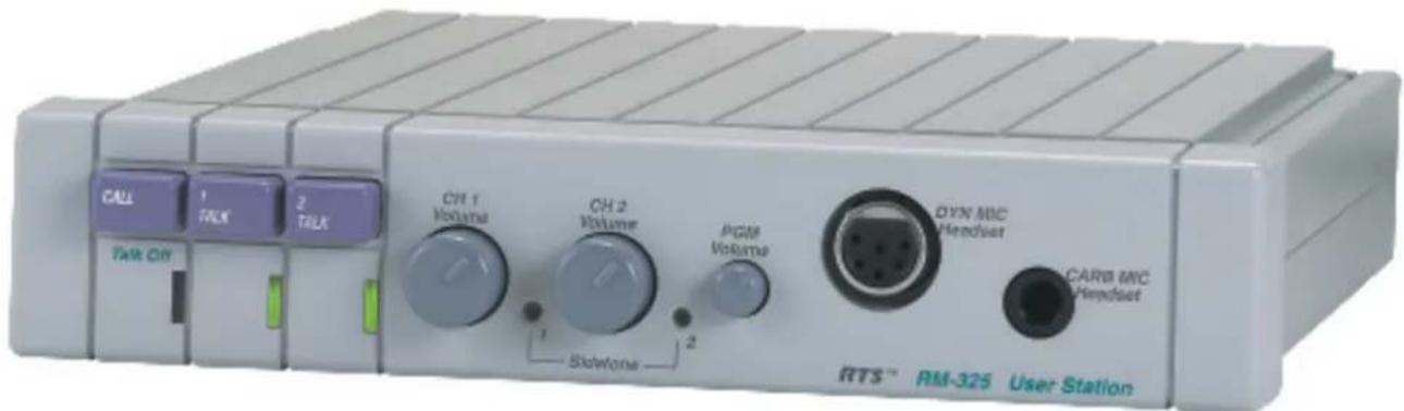
The RM-325 is a programmable, microprocessor controlled, rack-mounted intercom station for use with RTS™ two-wire intercom systems. Power for the RM-325 can be obtained from intercom channel one, channel two, or via "local power."
The RM-325 is a two-channel intercom station with connections for the intercom system, program input and headset/earset microphone or separate carbon microphone. When used with a stereo or mono headset/earset, the RM-325 allows full-duplex two channel voice communications. The 6-pin headset/earset connector accepts both 5 and 6-pin male XLR connectors.
FEATURES
Features of the RM-325 include:
- Call function that allows the user to send or receive signals to other devices on either of two intercom channels
- Send and receive microprocessor controlled Talk Off signal
- Other programmable options include: dual channel listen, stereo/mono, program input to the right or left headphone, enable/disable Talk Off, enable/disable Talk on one or both channels
- Powered externally, via the intercom system power supply on channel one, or via the auxiliary inputs connector
- Unswitched mic output at line level, via the auxiliary inputs connector
- Remote mic switch via either the carbon mic connector or via the auxiliary inputs connector
• Headset/earset jack set for intercom operation
CONNECTIONS & CONTROLS
The RM-325 has the following connections and controls:
- Two dual-mode talk switches, for latched or momentary operation
-
Separate volume controls for intercom channels 1 and 2
-
Separate sidetone controls for intercom channels 1 and 2
- Headset connections that accept an XLR type 5 or 6-pin male connector, or a 1/4" stereo phone plug
• Program input volume control - Program input from either a D-sub 15-pin male connector or a 1/4" stereo phone plug
- Line connector that accepts an XLR type 3-pin male connector for intercom lines and power input
- Line loop connector that accepts an XLR type 3-pin female connector for connection to additional intercom stations
- Connection for auxiliary inputs that accepts a D-sub 15-pin male connector
- Internal jumpers and dip switches that control several programmable options
SPECIFICATIONS
SYSTEM SPECIFICATIONS
DC Operating Limits:
5,000 ft. (#22 AWG wire), with power supply at one end
AC Operating Limits:
10,000 ft. (#22 AWG wire), "dry" line, with power supplies at both ends
System Capacitance:
0.3 μF, maximum (10,000 ft. cable at 30 pF/ft.)
GENERAL SPECIFICATIONS
Intercom System Power Supply Requirements:
30 VDC nominal (standard RTS™ line), 60 to 100 mA
"Local Power" Supply Requirements:
24 VDC nominal, 60 to 100 mA
Environmental Requirements:
Storage: -40°C to 125°C; 0% to 95% humidity, non-condensing
Operating: 0°C to 50°C; 0% to 95% humidity, non-condensing
Dimensions:
1.72" (44 mm) H x 8.2" (208 mm) W x 8" (203 mm) D
Weight:
2 lbs 12 oz (1.25 kg)
INTERFACE REQUIREMENTS
RTS™ Intercom Channel:
Output Level: 0.7 Vrms (0 dBu) nominal
Input Impedance: 200Ω ±5%
Bridging Impedance: greater than 10,000Ω
Call Signalling:
Send: 20 kHz ±100 Hz, 0.3 Vrms nominal
Receive: 20 kHz ±200 Hz, 100 mVrms
Talk Off Signalling:
Send: 24 kHz ±100 Hz, 0.3 Vrms nominal
Receive: 24 kHz ±200 Hz, 100 mVrms
Noise Contribution: less than -75 db on the line
Common Mode Rejection Ratio: greater than 40 dB
from the line
Program Input:
Maximum Input Level: 20 dBu
Nominal Input Level: -10 to +8 dBu
Frequency Response: 100 Hz to 12 kHz ±3 dB
Current Source:
Transfer Ratio: 3.3 mA/V = 3.3 millisiemans
Output: ±5 mA into 200Ω, ±1 Vpeak (limiter
threshold)
HEADPHONE AMPLIFIER
Voltage Gain:
30±3 dB from the line
Maximum Output:
150 mW into 50Ω
Frequency Response:
100 Hz to 8 kHz ±3 db nominal
Output Voltage Level:
8 volts peak-to-peak
Headphone Impedance:
50 to 600Ω
Sidetone:
20 dB minimum range, adjustable
MICROPHONE PREAMPLIFIER
Maximum Voltage Gain:
54 dB
Frequency Response:
100 Hz to 8 kHz, nominal
Input Impedance:
1,000Ω, balanced
Limiter Range:
30 dB
Total Harmonic Distortion:
Less than 0.2% nominal at Channel output
CONNECTOR PIN CONFIGURATIONS
Headset Connector
Type: 1/4" Stereo Plug
Tip Microphone input high
Ring Headphone high
Sleeve Common
Headset Connector
Type: XLR-6F
Pin 1 Headset microphone low
Pin 2 Headset microphone high
Pin 3 Common
Pin 4 Headphone left high
Pin 5 Headphone right high
Pin 6 (Center pin) Remote microphone control
(an XLR-5F does not have the center pin)
Intercom Line Input Connector
Type: XLR-3F
Pin 1 Common
Pin 2 Intercom channel 1 (audio) and +30 VDC
Pin 3 Intercom channel 2 (audio)
Intercom Line Loop Connector
Type: XLR-3M
Pin 1 Common
Pin 2 Intercom channel 1 (audio) and +30 VDC
Pin 3 Intercom channel 2 (audio)
Program Input Connector
Type: 1/4" Stereo Plug
Tip Program input high
Ring Program input low
Sleeve Common
Auxiliary Inputs Connector
Type: DB-15F
Pin 1 Program input high
Pin 2 Mono headphone high
Pin 3 Unswitched mic high
Pin 4 Foot switch channel 1
Pin 5 Foot switch channel 2
Pin 6 Local power (+24 VDC)
Pin 7 Remote mic switch
Pin 8 Not Used
Pin 9 Program input low
Pin 10 Mono headphone low
Pin 11 Unswitched mic low
Pin 12 Foot switch channel 1 common
Pin 13 Foot switch channel 2 common
Pin 14 Local power common
Pin 15 Remote mic switch common
NOTE: The numbers refer to the callouts in Figure 2-1.
- CALL Button and Indicator
The Call function allows the user to send or receive signals to other devices on the intercom channel selected. The CALL button operates in two ways:
Call receive:
When there is an incoming call the red CALL and TALK indicators will flash.
Call send:
To send a call signal to all stations on a channel, tap the TALK button for the desired channel, then press and hold the CALL button until a verbal response is received. The indicator will glow red.
- Talk-Off
To send a Talk-Off signal to all stations on a channel, turn off both TALK indicators, then tap the CALL button three quick taps. While the red CALL indicator is on, momentarily press the TALK button for the desired channel.
- TALK1 and TALK2 Buttons and Indicators
The TALK buttons activate the headset microphone on the selected channel and operates in two ways:
Latched Mode:
Tap the button once, then begin to talk. The indicator will glow green. Tap the button again when finished with a conversation.
Momentary Mode:
Press and hold the button to talk momentarily. The indicator will glow green while the button is held. Release the button when finished talking.
- CH1 and CH2 Volume Controls
Use these controls to adjust the headset/earset listen level for each channel.
- Sidetone Controls for Channel 1 and Channel 2
When using a headset, these controls adjust the level of your own voice heard in the earphones. To adjust the level for one channel, tap that channel's TALK button once to turn on the headset microphone. Then, use a small flat-blade screwdriver to increase or decrease your voice level while talking into the microphone.
- PGM Volume Control
Use this control to adjust the program input volume.
- DYN MIC Headset Connector
This connector accepts an RTS™ boom-microphone headset.
- CARB MIC Headset Connector
This connector accepts a carbon microphone headset/earset with a 1/4" stereo phone plug, or a remote mic switch with a 1/4" stereo phone plug.
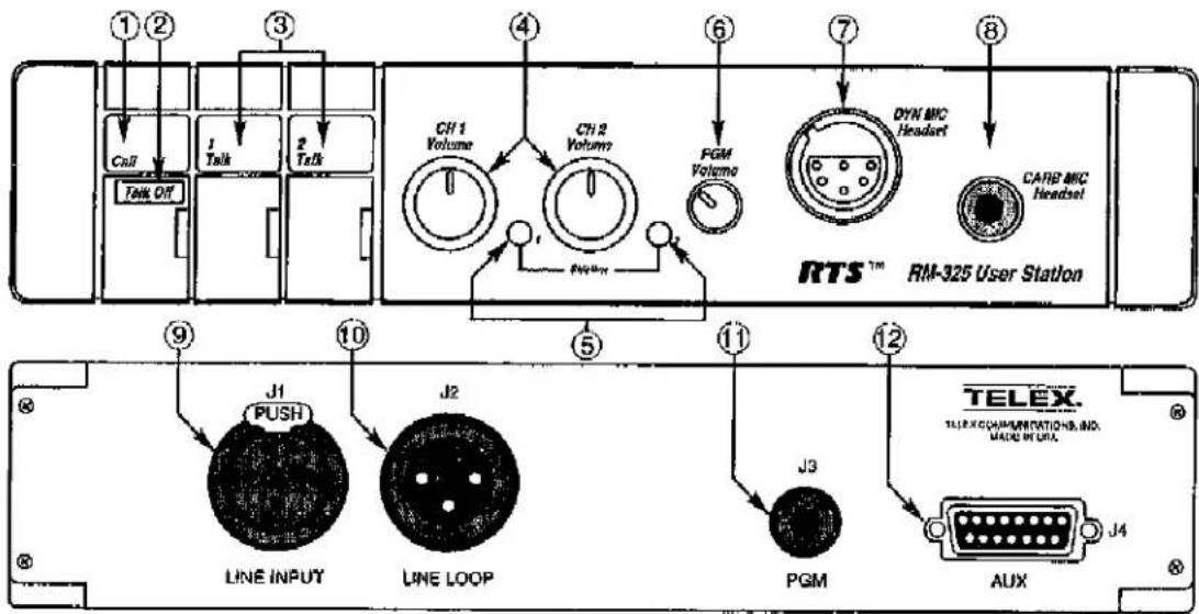
Figure 2-1. RM-325 Connections and Controls
- LINE INPUT Connector
The RM-325 intercom channel is connected via a 3-pin female connector. When the RM-325 is powered from the intercom system power supply, it will turn on with the intercom system.
- LINE LOOP Connector
The intercom system can be extended by attaching additional stations to this 3-pin male connector. Channel 1 and 2 audio, as well as system power is available here.
- PGM Input Connector
This connector accepts program input via a 1/4" stereo phone plug. In a television studio intercom system, the program input is usually the actual program audio signal. In another intercom system, the program input can be any auxiliary audio signal, such as background music.
- AUX Input Connector
This 15-pin connector provides an alternate method of connection for "local power," program input, foot switches, headphone and unswitched mic audio, and remote mic switch.
RM-325 OPERATION
This section describes operation of the RM-325 as supplied from the factory. Use of an RTS™ power supply to power the intercom system is assumed. For options, see the "Internal Switches and Jumpers" section. For use of an alternate power source, see the "Alternate Powering Methods" section.
Connecting a Headset
Connect a headset using one of the two headset connectors on the front panel. The DYN MIC headset connector is for a monaural or stereo dynamic-mic headset. The CARB MIC headset connector is for a monaural carbon-mic headset. Refer to the specifications for pin-outs of these connectors.
Connecting To the Intercom Channels
Connect the RM-325 to the intercom system using the LINE INPUT connector on the back panel.
If desired, connect additional intercom stations to the intercom system using the LINE LOOP connector on the back panel.
Adjusting the Sidetone
To adjust the level of your own voice heard in the earphones, tap the TALK button once to turn on the headset microphone. Then, use a small flat-blade
screwdriver to increase or decrease your voice level while talking into the microphone.
Using the Momentary Mode to Make a Call
- Tap the CALL button. The red CALL indicator will flash for approximately 30 seconds, indicating that a call signal is ready to be sent.
- While the CALL indicator is flashing, press and hold the desired TALK button to send the call signal.
- When a response is heard, release the TALK button to remove the call signal, then press and hold the TALK button again to begin your conversation.
- Release the TALK button when finished with your conversation.
Using the Latched Mode to Make a Call
- If the talk function is enabled for the desired channel, tap the TALK button for the channel to be called (the green TALK indicator should be lit).
- Press and hold the CALL button. The red CALL indicator will light while the button is pressed, indicating that a call signal is being sent. When a response is heard, release the CALL indicator and begin your conversation.
- Tap the TALK button again when finished with your conversation.
Receiving a Call
- When there is an incoming call on a channel, the red CALL indicator will flash. If the audio listen function is disabled on that channel, you will not be able to hear the incoming call.
- If a TALK indicator is also flashing, this indicates that you need to activate the talk function on that channel to begin your conversation.
- If no TALK indicator is flashing, this indicates that the talk function is already activated for that channel; simply begin your conversation.
Sending a Talk-Off Signal
The RM-325 can generate an inaudible signal which can be used to deactivate the microphones on other intercom stations connected to the intercom channel. (When the Talk-Off feature is enabled, it can be used with RTS ^TM models BP-318, BP-325, BP-350, MCE-325 and MRT-327). This feature is useful when there is a microphone activated on an unattended intercom station, and it is causing noise on the intercom channel. To send a Talk-Off signal:
- Turn off both TALK indicators on the RM-325.
- Tap the CALL button three quick taps. The red CALL indicator will turn on for a few seconds.
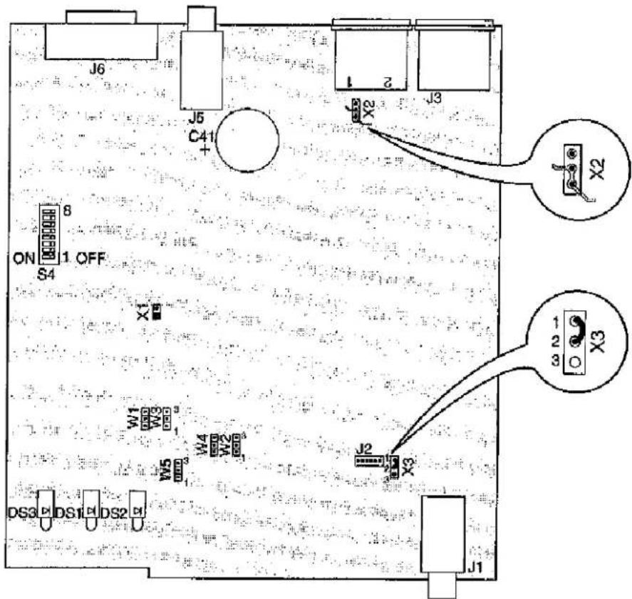
Figure 2-2. Internal Jumpers and Switches
- While the red CALL indicator is on, momentarily press the TALK button for the desired channel. This will send the Talk-Off signal and turn off all remote microphones on that channel.
INTERNAL SWITCHES AND JUMPERS
There are several internal switches and jumpers that affect operation. These are described below. To gain access to the switches and jumpers, disconnect all power and line connections. Remove four screws from the back panel and remove the top cover of the case. The jumper and switch locations are shown in Figure 2-2.
TABLE 2-1. INTERNAL JUMPERS
| JUMPER NUMBER | JUMPER FUNCTION | DEFAULT SETTING |
| W1 | CH1 Intercom Audio Listen: Pins 1&2 shorted enables channel 1 audio, Pins 2&3 shorted disables channel 1 audio | 1 & 2 shorted |
| W2 | CH2 Intercom Audio Listen: Pins 1&2 shorted enables channel 2 audio, Pins 2&3 shorted disables channel 2 audio | 1 & 2 shorted |
| W3 | Left Headphone Program Input: Pins 1&2 shorted enables program audio, Pins 2&3 shorted disables program audio | 1 & 2 shorted |
| W4 | Right Headphone Program Input: Pins 1&2 shorted enables program audio, Pins 2&3 shorted disables program audio | 1 & 2shorted |
| W5 | Stereo/Mono operation: Pins 1&2 shorted, channel 1 is heard in the left headphone, channel 2 is heard in the right headphone (stereo) Pins 2&3 shorted, both channels are heard in both headphones (mono) | 1 & 2shorted |
| X1 | Audible Alert Option Speaker location to be determined | 1 & 2open |
| X2 | Channel Power Source: Pins 2&3 shorted enables power from channel 1, Pins 1&2 shorted enables power from channel 2 | 2 & 3shorted |
| X3 | Carbon Mic/Remote Mic Switch: Pins 1&2 shorted enables use of carbon mic headset: Pins 2&3 shorted enables use of remote mic switch via CARB MIC jack | 1 & 2shorted |
TABLE 2-2. INTERNAL DIP SWITCHES
| DIP SWITCH NUMBER | SWITCH FUNCTION | DEFAULT SETTING |
| S4-1 | Call Signal Transmit Disable | Off |
| S4-2 | CH2 Momentary Only Talk: Off enables both latched and momentary operation: On enables momentary operation only | Off |
| S4-3 | CH2 Talk Disable: On disables channel 2 talk function: Off enables channel 2 talk | Off |
| S4-4 | CH1 Talk Disable: On disables channel 1 talk function: Off enables channel 1 talk | Off |
| S4-5 | CH1 Momentary Only Talk: Off enables both latched and momentary operation: On enables momentary operation only | Off |
| S4-6 | Talk-Off Transmit: On allows RM-325 to send Talk-Off signal: Off prevents RM-325 from sending Talk-Off signal | On |
| S4-7 | Not used | Off |
| S4-8 | Talk-Off Receive: On allows RM-325 to receive Talk-Off signal from other stations: Off prevents RM-325 from receiving Talk-Off signal | On |
Intercom Audio Listen Option
Intercom Audio Listen is factory set to be enabled on both channels. Setting W1 to the off position will disable intercom audio on channel 1 (usually the left headphone of a stereo headset). Setting W2 to the off position will disable intercom audio on channel 2 (usually the right headphone of a stereo headset).
This option could be used, for example, when you want to use the left side of a stereo headphone exclusively for program audio input and the right side for one channel of intercom audio. In this case you would:
- Set W5 for stereo operation.
- Set W1 to "off" to disable channel 1 intercom audio.
- Set DIP switch S4-4 to "on" to disable channel 1 talk.
- Set W3 and W4 for left channel program input,
Program Input Audio Option
To use program input audio:
-
Connect program input to either the PGM input connector or to the AUX inputs connector. (Refer to the connector pin configurations for the proper connections.)
-
If you are using a stereo headset, set W3 and W4 for the desired operation. (If you are using a mono headset, set both W3 and W4 to "on".)
- Adjust program input volume using the PGM volume control.
Stereo/Mono Option
When a stereo headset is connected to the DYN MIC Headset connector, W5 can be set for stereo or mono operation. With W5 set in the stereo position, intercom channel 1 will be heard in the left headphone only, and channel 2 will be heard only in the right headphone. In the mono position, both intercom channels (and program audio if connected) will be heard in both headphones.
If you are using monaural headphones, W5 may be left in the stereo position.
Remote Mic Switch Option
The CARB MIC Headset connector may be used to connect either a headset or a remote mic on/off switch. (If you are using a carbon mic headset, but still wish to use a remote mic switch, the AUX connector may alternatively be used for the mic switch.) To use the CARB MIC Headset connector for a remote mic on/off switch;
- Set X3 to the remote mic switch setting.
- Use a stereo phone plug to connect the remote switch to the CARB MIC Headset jack.
- To use the remote mic switch, set one or both TALK buttons to the latched-on position.
NOTE: The TALK indicators may still be turned on or off from the RM-325; however, the remote mic switch will not work unless the TALK indicators are first turned on at the RM-325.
-
To begin your conversation, press and release the remote mic switch, the TALK indicator(s) will go off then on.
-
To end your conversation, press and release the remote mic switch again, the TALK indicator(s) will go off then on.
Momentary/Latched Talk Option
As supplied, the TALK buttons feature a dual-action momentary/latching operation: press and hold for momentary talk, then release when finished; or tap to latch "on" for hands-free talk, and tap again to turn off when finished talking.
If desired, the latching operation may be defeated, and the TALK buttons may be operated in momentary mode only. Use DIP switches S4-1 and S4-5 to disable latching operation on the desired channel.
Channel Talk Option

Setting DIP switch S4-3 to the "on" position will disable the channel 2 TALK button. Setting DIP switch S4-4 to the "on" position will disable the channel 1 TALK button.
Send Talk-Off Option
As supplied, the RM-325 can generate an inaudible Talk-Off signal which can be used to deactivate the TALK buttons on other intercom stations connected to an intercom channel. To turn this feature off, set DIP switch S4-6 to the "off" position.
Receive Talk-Off Option
As supplied, other intercom stations can deactivate the TALK buttons on the RM-325 using the Talk-Off feature from their intercom stations. To disable this feature, set DIP switch S4-8 in the "off" position.
ALTERNATE POWERING METHODS
General
The unique design of RTS^TM power supplies permits power to be carried on an audio channel. When using an RTS^TM power supply (PS-15 or PS-31) to power the intercom system, power is carried to the RM-325 on pin 2 of the LINE INPUT connector along with the channel 1 audio. Pin 1 is the DC return. RTS^TM power supplies also provide the proper terminating impedance for each intercom channel.
If the standard channel 1 RTS^TM power supply is not available, there are several options for connecting power and intercom audio:
• One channel operation with a non-RTS™ power supply
- Two channel operation with "local power" via the AUX inputs connector
• RTS™ power via channel 2
These options are discussed below.

Figure 2-3. Wiring for 1-Channel/External Power
One Channel Operation With a Non-RTS™ Power Supply
This method uses channel 1 only to connect the non-RTS™ power supply. Audio on channel 1 will be unusable as the power supply will look like a short circuit at audio frequencies. Channel 2, however, will still be operational. Also, channel 2 will require a terminating impedance, since this is not supplied by the non-RTS™ power supply.
Using an XLR-3M connector, connect the external power source and the channel terminating components to the LINE INPUT connector as shown in Figure 2-3.
If desired, the LINE LOOP connector may be used to connect power and audio to additional intercom stations.
Two Channel Operation With "Local Power"
This method maintains two audio channels, but requires external impedance matching for the audio lines. In a "local power" system, each RM-325 is powered via the AUX inputs connector, and the LINE LOOP connector is used for channel impedance matching. The "local power" supply must provide 18 to 24 VDC at 100 mA peak.
- Refer to Figure 4-1. Remove all four screws (item 11) on the back connector panel of the RM-325.
- Remove the top cover assembly.
- On the top side of the main circuit board, cut the trace between pins 2 and 3 at X2 as shown in Figure 2-2.
- Reassemble the RM-325,
- Using a DB-15M connector, connect the local power source to the AUX inputs connector. Connect +DC to pin 6 and connect power supply common to pin 14 on the AUX inputs connector.
- Using an XLR-3F plug, connect intercom channels and termination components as shown in Figure 2-4. Plug this connector into the LINE LOOP jack of the RM-325.

Figure 2-4. Termination for 2-Channel/External Power
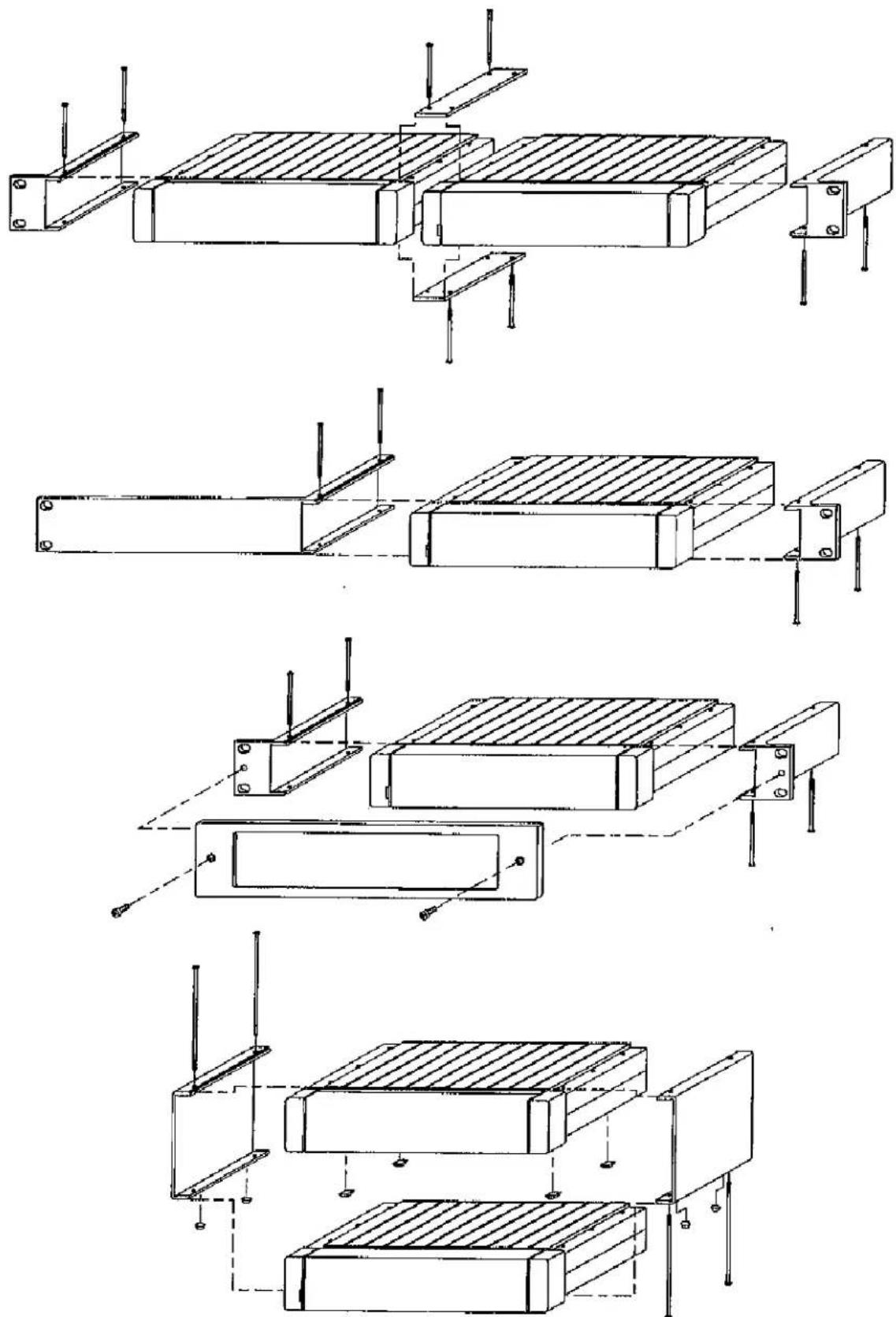
Figure 2-5. Optional Mounting Configurations
RTS™ Power Via Channel 2

This method uses the RTS^TM power supply on channel 2 instead of the standard channel 1 connection. As with the standard RTS^TM channel 1 power connection, this method maintains two audio channels and does not require external impedance matching. In a channel 2 RTS^TM power system, the LINE LOOP connector is usable for connecting channel audio and channel 2 power to other intercom stations.
- Refer to Figure 4-1. Remove all four screws (item 11) on the back connector panel of the RM-325.
- Remove the top cover assembly.
- On the top side of the main circuit board, cut the trace between pins 2 and 3 at X2 as shown in Figure 2-2.
- On the top side of the main circuit board, add a jumper between pins 2 and 1 at X2 as shown in Figure 2-2.
- Reassemble the RM-325.
- Ensure that the RTS ^TM power is connected to channel 2 on the intercom line. (Refer to the Connector Pin Configurations for the proper connections to the LINE INPUT connector.)
MOUNTING CONFIGURATIONS
Optional mounting configurations for modular RTS™ intercom stations are shown in Figure 2-5 and include rack-mount, console-mount, desk-top and portable stations.
INSTALLATION GUIDELINES
This section contains some guidelines on installing the RM-325, including:
• Choosing headsets and handsets
• Headphone sound isolation
- Cabling requirements
Use the information provided here and elsewhere in the manual to help you determine the type of system, the powering method, the power supply(ies), and the cabling requirements. Create a system block diagram and equipment list, before installing the system.
Choosing Headsets or Handsets

The RM-325 accepts a wide variety of headsets and handsets. Headset or handset choice depends on operating environment, operating requirements, and personal taste.
Table 2-3 shows typical operating environments and the level of background noise present. The background noise is measured using a Sound Pressure Level (SPL) meter, which measures the sound pressure level in decibels. SPL is useful for measuring environmental background noise, comparing headphone efficiency, and predicting whether speech communication is possible.
TABLE 2-3. ENVIRONMENTAL NOISE, SOUND PRESSURE LEVEL AT 10 METERS
| SOURCE | SPL |
| Aircraft | 120 dB to 160 dB |
| Orchestra, 75 piece,(peaks) or Pipe Organ,(peaks) | 140 dB |
| Rock Concert | 110 dB to 140 dB |
| Piano, (peaks) | 120 dB |
| Blaring Radio | 110 dB |
| Centrifugal VentilatingFan | 110 dB |
| Auto on Highway | 100 dB |
| Vaneaxial VentilatingFan | 90 dB |
| Voice, Shouting | 90 dB |
| Factory | 75 dB |
| Voice, Conversational | 70 dB |
| Residence | 45 dB |
| Television Studio | 25 dB to 35 dB |
| Voice, Whisper | 30 dB |
- A very noisy/loud environment usually requires headphones that prevent outside sound from leaking in (again, good acoustic isolation), headphones that can produce a loud, clear sound, and noise cancelling microphones.
- Understanding speech in a noisy environment requires that the sound from the headphones is as loud or louder than the sound leaking into the headphones from the noisy environment.
- In general, the loudness of a headphone depends upon its ability to absorb power at a given voltage (power=voltage squared divided by the impedance) and the efficiency of its design. Practically, the impedance has a larger effect with present day headsets.
- Low impedance headphones are louder, causing the RM-325 to draw more current from the power supply. High impedance headphones are not as loud, drawing less current from the power supply. The RM-325 design range of impedances for the headphone part of the headset is 25Ω to 600Ω.
• Efficiency is the amount of SPL (Sound Pressure Level) produced for a given electrical input power.
Headphone Sound Isolation
The ability of headphones to shut out unwanted environmental noise varies from none (0 dB isolation) to about 1/8th as loud (30 dB isolation). The degree of isolation depends both on the design of the headset and the frequency content of the environmental noise. Lightweight, "open" headsets have almost no (0 dB) isolation. The trade off is that lightweight headsets are very comfortable and can be worn for long periods (8 to 12 hours) without physical discomfort from the earmuffs or headband. Because there is no isolation, care must be taken that the sound signals from lightweight headsets are not unintentionally leaked into microphones. In general, the comfort of headsets depends upon their weight, padding and design.
Isolation, Headset Microphones
In high noise environments, the headset microphone should be a noise cancelling type.
Cabling Requirements
Wire Size
It may be necessary to overcome power losses by increasing conductor size over long runs (more than one kilometer). Normal conductor size is #22 AWG. The maximum allowable loop resistance is determined by the power supply voltage, the loop current and the user station minimum operating voltage. The maximum loop resistance equals the difference of the power supply voltage and the minimum operating voltage divided by the maximum loop current (power required by the user station(s)).
Example: A headset station (with 25Ω headphones) uses up to 70 mA. The power supply voltage is 26 VDC and the user station minimum operating voltage is 18 VDC. Then the maximum allowable loop resistance is:
$$ (2 6 - 1 8) \mathrm{V} / 0. 0 7 \mathrm{A} = 1 1 4 \Omega $$
This corresponds to an operating distance of 1.1 kilometers (3,562 feet) for a #22 AWG wire pair using a single user station with 25 ohm headphones. Data for these calculations can be found in standard electrical wire tables.
Grounding
System circuit ground should not be directly connected to "earth" or "chassis" ground (where directly means a connection an ohmeter would show).
In order to prevent a buildup of voltage across the system capacitance, the power supply has a bleeder resistor to chassis ground (22 kΩ). If the system has no RTS™ Systems power supply, such a bleeder resistor should be supplied at a central point in the system.
The basic benefit of not "earth" grounding the RTS^TM System circuit return is that it permits continued operation during an accidental system ground fault. This accidental grounding can happen as the result of a pinched wire or a scraped cable that has been pulled across a sharp edge. A single accidental ground can be tolerated by the system until the fault can be cleared and (with luck) before a second ground fault can cause noise or overload. Another benefit of not "earth" grounding the circuit return is that it prevents the introduction of noise through "earth" currents from other equipment. If the RTS^TM circuit ground conducts these currents, it is likely that they will be heard as interfering noise on the communication line.
Signal
Two conductors are required for a one channel system, and three conductors are required for a two channel system. Shielded cable is recommended.
Two channel applications may use either standard microphone cable (for convenience) or two-twisted-pair cable (less expensive than microphone cable). Standard wire size for the system is #22 gauge wire for interconnection. For permanent installations it is recommended that each channel should have individually shielded twisted pair of at least #22 gauge wire; such as Belden #8723 or 9402 for 2 channels. This will reduce interference and help maintain a low crosstalk figure between channels. Connections are as follows:
First shielded pair: connect shield and black to common (pin 1 in two channel system), connect color to channel 1 (pin 2 in two channel system);
Second shielded pair: connect shield and black to common (pin 1 in two channel system), connect color to channel 2 (pin 3 in two channel system).
The audio signal line level is maintained between -10 dBu and 0 dBu (between 0.24 and 0.77 Vrms). These levels are low enough to prevent crosstalk into other equipment (such as TV cameras) yet high enough to reduce external interference to the TW System.
The 200Ω line impedance is high enough to allow communication over line lengths of 1.6 kilometers (one mile) and low enough to permit an adequate speech bandwidth with 3.2 kilometers of accumulated cable. In most systems the 200Ω impedance gives a high fidelity bandwidth with low losses.
When using equipment in rain or conditions of excessive moisture, always protect the equipment with plastic covers and make sure all cable connectors are lifted out of mud, snow or moisture and protected with plastic or tape. Water mud and snow in connectors can cause considerable hum.
SECTION 3. REPLACEMENT PARTS
WHERE TO OBTAIN PARTS
Parts may be obtained directly from 'Telex at:
Telex/RTS Systems
12000 Portland Ave. S.
Burnsville, MN 55337
877-863-4169
Fax: 800-323-0498
MECHANICAL PARTS
| FINAL ASSEMBLY(Refer to Figure 4-1 for Item No. locations) | ||
| Item No. | Description | Part No. |
| 1 | Bezel, RM-325 | 9070-7491-000 |
| 2 | Insert, 6 Pin Connector | 2018-0077-00 |
| 3 | Lightpipe, Call Button | 4501-0062-00 |
| 4 | Knob, Volume | 2703-0037-00 |
| 5 | Key Cap, Call | 9150-6643-05 |
| 6 | Key Cap, Talk 1 | 9150-6643-01 |
| 7 | Key Cap, Talk 2 | 9150-6643-03 |
| 8 | Stem, Switch | 2705-0021-00 |
| 9 | P.C. Board Assy. | 9030-7491-000see Fig. 4-2 |
| 10 | Case, Extruded | 9060-6260-00 |
| 11 | Screw, Case | 9160-6305-00 |
| 12 | Screw, #4-40 x 3/8" | 51845-039 |
| 13 | Scrow, Lock, #4-40 | 58421-000 |
| 14 | Screw, M3 x 7.0 mm | 16030D8 |
| 15 | Panel, Rear RM-325 | 9080-7491-000 |
| 16 | Valox Flim, 0.010 Thk., 7.0" X 6.75" | 1303-0009-00 |
| 17 | Knob, Volume | 2703-0034-00 |
| 18 | Not Used | |
| 19 | Not Used | |
| 20 | Not Used | |
| 21 | Not Used | |
| 22 | Not Used | |
| 23 | Not Used | |
| 24 | Housing, Connector, 6 Pin | 59958-006 |
| 25 | Terminal | 59958-200 |
ELECTRICAL PARTS
| CIRCUIT BOARD ASSEMBLY(Refer to Figures 4-3 and 4-4) | ||
| Ref. No. | Description | Part No. |
| Heatsink | 45020018-00 | |
| C1 | Capacitor, EL, SM, 47 μF, 10V | 102884-215 |
| C2 | Capacitor, CM, SM, 100 pF, 50V | 102879-204 |
| CIRCUIT BOARD ASSEMBLY(Refer to Figures 4-3 and 4-4) | ||
| Ref. No. | Description | Part No. |
| C3 | Capacitor, EL, SM, 47 μF, 10V | 102884-215 |
| C4 | Capacitor, CM, SM, 1000 pF, 50V | 102881-327 |
| C5 | Capacitor, CM, SM, 1000 pF, 50V | 102881-327 |
| C6 | Capacitor, CM, SM, 0.1 μF, 50V | 102881-351 |
| C7 | Capacitor, CM, SM, 0.1 μF, 50V | 102881-351 |
| C8 | Capacitor, CM, SM, 0.1 μF, 50V | 102881-351 |
| C9 | Capacitor, EL, SM, 47 μF, 10V | 102884-215 |
| C10 | Capacitor, CM, SM, 470 pF, 50V | 102879-212 |
| C11 | Capacitor, CM, SM, 0.1 μF, 50V | 102881-351 |
| C12 | Capacitor, EL, SM, 22 μF, 35V | 1099R226-3G |
| C13 | Capacitor, CM, SM, 0.01 μF, 50V | 102881-339 |
| C14 | Capacitor, CM, SM, 1000 pF, 50V | 102881-327 |
| C15 | Capacitor, CM, SM, 10 pF, 50V | 102879-271 |
| C16 | Capacitor, EL, SM, 1 μF, 50V | 102884-606 |
| C17 | Capacitor, CM, SM, 0.1 μF, 50V | 102881-351 |
| C18 | Capacitor, CM, SM, 100 pF, 50V | 102879-204 |
| C19 | Capacitor, CM, SM, 100 pF, 50V | 102879-204 |
| C20 | Capacitor, CM, SM, 100 pF, 50V | 102879-204 |
| C21 | Capacitor, CM, SM, 10 pF, 50V | 102879-271 |
| C22 | Capacitor, EL, SM, 22 μF, 35V | 1099R226-3G |
| C23 | Capacitor, EL, SM, 22 μF, 35V | 1099R226-3G |
| C24 | Capacitor, EL, SM, 22 μF, 35V | 1099R226-3G |
| C25 | Capacitor, CM, SM, 100 pF, 50V | 102879-204 |
| C26 | Capacitor, EL, SM, 22 μF, 35V | 1099R226-3G |
| C27 | Capacitor, CM, SM, 100 pF, 50V | 102879-204 |
| C28 | Capacitor, CM, SM, 100 pF, 50V | 102879-204 |
| C29 | Capacitor, CM, SM, 10 pF, 50V | 102879-271 |
| C30 | Capacitor, EL, SM, 22 μF, 35V | 1099R226-3G |
| C31 | Capacitor, EL, SM, 22 μF, 35V | 1099R226-3G |
| C32 | Capacitor, EL, SM, 22 μF, 35V | 1099R226-3G |
| C33 | Capacitor, CM, SM, 100 pF, 50V | 102879-204 |
| C34 | Capacitor, EL, SM, 1 μF, 50V | 102884-606 |
| C35 | Capacitor, EL, SM, 1 μF, 50V | 102884-606 |
| C36 | Capacitor, CM, SM, 1000 pF, 50V | 102881-327 |
| C37 | Capacitor, CM, SM, 1000 pF, 50V | 102881-327 |
| C38 | Capacitor, EL, SM, 1 μF, 50V | 102884-606 |
| C39 | Capacitor, CM, SM, 100 pF, 50V | 102879-204 |
| C40 | Capacitor, EL, SM, 47 μF, 10V | 102884-215 |
| C41 | Capacitor, EL, RA, 4700 μF, 35V | 1513R478-4G |
| C42 | Capacitor, EL, SM, 47 μF, 10V | 102884-215 |
| C43 | Capacitor, EL, SM, 47 μF, 10V | 102884-215 |
| C44 | Capacitor, CM, SM, 0.1 μF, 50V | 102881-351 |
| C45 | Capacitor, CM, SM, 0.1 μF, 50V | 102881-351 |
| C46 | Capacitor, EL, SM, 22 μF, 35V | 1099R226-3G |
| C47 | Capacitor, CD, RA, 0.1 μF, 500V | 1510R104-2Q |
| C48 | Capacitor, EL, 1000 μF, 16V | 51821-072 |
| C49 | Capacitor, EL, 1000 μF, 16V | 51821-072 |
| C50-C99 | Not Used | |
| C100 | Capacitor, EL, SM, 1 μF, 50V | 102884-606 |
| C101 | Capacitor, EL, SM, 1 μF, 50V | 102884-606 |
| C102 | Capacitor, CM, SM, 10 pF, 50V | 102879-271 |
| C103 | Capacitor, CM, SM, 10 pF, 50V | 102879-271 |
| C104 | Capacitor, CM, SM, 100 pF, 50V | 102879-204 |
| C105 | Capacitor, CM, SM, 10 pF, 50V | 102879-271 |
| C106 | Capacitor, CM, SM, 0.1 μF, 50V | 102881-351 |
| C107 | Capacitor, CM, SM, 1000 pF, 50V | 102881-327 |
| C108 | Capacitor, CM, SM, 0.1 μF, 50V | 102881-351 |
| C109 | Capacitor, CM, SM, 0.1 μF, 50V | 102881-351 |
| C110 | Capacitor, EL, SM, 47 μF, 10V | 102884-215 |
| C111 | Capacitor, CM, SM, 0.1 μF, 50V | 102881-351 |
| C112 | Capacitor, CM, SM, 1000 pF, 50V | 102881-327 |
| C113 | Capacitor, CM, SM, 0.1 μF, 50V | 102881-351 |
| C114 | Capacitor, CM, SM, 0.1 μF, 50V | 102881-351 |
| C115 | Capacitor, EL, SM, 47 μF, 10V | 102884-215 |
| C116 | Capacitor, EL, SM, 1 μF, 50V | 102884-606 |
| C117 | Capacitor, EL, SM, 1 μF, 50V | 102884-606 |
| CC1 | Capacitor, CM, SM, 0.1 μF, 50V | 102881-351 |
| CC2 | Capacitor, CM, SM, 0.1 μF, 50V | 102881-351 |
| CC3 | Capacitor, CM, SM, 0.1 μF, 50V | 102881-351 |
| CC4 | Capacitor, CM, SM, 0.1 μF, 50V | 102881-351 |
| CC5 | Capacitor, CM, SM, 0.1 μF, 50V | 102881-351 |
| CC6 | Capacitor, CM, SM, 0.1 μF, 50V | 102881-351 |
| CC7 | Capacitor, CM, SM, 0.1 μF, 50V | 102881-351 |
| CC8, CC9 | Not Used | |
| CC10 | Capacitor, CM, SM, 0.1 μF, 50V | 102881-351 |
| CC11 | Capacitor, CM, SM, 0.1 μF, 50V | 102881-351 |
| CC12 | Capacitor, CM, SM, 0.1 μF, 50V | 102881-351 |
| CC13 | Capacitor, CM, SM, 0.1 μF, 50V | 102881-351 |
| CC14 | Capacitor, CM, SM, 0.1 μF, 50V | 102881-351 |
| D1 | Diode, SM, Switching, 914/4148 | 58711-100 |
| D2 | Diode, SM, Switching, 914/4140 | 58711-100 |
| D3 | Diode, SM, Switching, 914/4148 | 58711-100 |
| D4 | Diode, 1A, 400V, IN4004 | 16016481-SM |
| D5 | Diode, 1A, 400V, IN4004 | 16016481-SM |
| D6 | Diode, SM, Zener TVS, 1500W, 1SMC33A | 16010004-SM |
| D7 | Diode, SM, Switching, 914/4148 | 58711-100 |
| D8 | Diode, SM, Switching, 914/4148 | 58711-100 |
| D9 | Diode, SM, Switching, 914/4148 | 58711-100 |
| D10 | Diode, SM, Switching, 914/4148 | 58711-100 |
| D11 | Diode, SM, Switching, 914/4148 | 58711-100 |
| D12 | Diode, SM, Switching, 914/4148 | 58711-100 |
| D13 | Diode, SM, Switching, 914/4148 | 58711-100 |
| D14-D100 | Not Used | |
| D101 | Diode, SM, Switching, 914/4148 | 58711-100 |
| D102 | Diode, SM, Switching, 914/4148 | 58711-100 |
| D103 | Diode, SM, Switching, 914/4148 | 58711-100 |
| DS1 | LED, T-1 3/4, Green | 18014740-00 |
| DS2 | LED, T-1 3/4, Green | 18014740-00 |
| DS3 | LED, T-1 3/4, Red | 18010027-00 |
| LED, T-1 3/4, Mount | 18010028-00 | |
| FB1 | Inductor, Ferrite Bead | 24040001-00 |
| FB2 | Inductor, Ferrite Bead | 24040001-00 |
| FB3 | Inductor, Ferrite Bead | 24040001-00 |
| FB4 | Inductor, Ferrite Bead | 24040001-00 |
| J1 | Connector, PC Mount Jack | 20130049-00 |
| J2 | Connector, ST Locking, 0.059, M-6 | 59958-106 |
| CIRCUIT BOARD ASSEMBLY(Refer to Figures 4-3 and 4-4) | ||
| Ref. No. | Description | Part No. |
| J3 | Connector, RA XLR, M-3 | 59892-003 |
| J4 | Connector, RA XLR, 3-F | 20180081-00 |
| J5 | Connector, PC Mount Jack | 20130049-00 |
| J6 | Connector, RA HD 2-Row D-Sub, F-15 | 59926-015 |
| Q1 | Transistor, SM, SI NPN, MMBT5088 | 102210-000 |
| Q1 | Transistor, N-JFET, SST-108 | 54750-000 |
| Q2 | Transistor, SM, SI NPN, MMBT5088 | 102210-000 |
| Q3 | Transistor, SM, SI NPN, MMBT5088 | 102210-000 |
| Q4 - Q9 | Not Used | |
| Q10 | Transistor, SM, SI, PNP, MBT5087 | 16025087-SM |
| Q11 | Not Used | |
| Q12 | Transistor, SM, SI, PNP, MBT5087 | 16025087-SM |
| Q13 | Transistor, SM, SI, PNP, MST5087 | 16025087-SM |
| Q14 | Transistor, SM, SI, PNP, MBT5087 | 16025087-SM |
| Q15 | Transistor, SM, SI NPN, MMBT5088 | 102210-000 |
| R1 | Resistor, SM, 22 kΩ, 5%, 1/8W | 102513-223 |
| R2 | Resistor, SM, 22 kΩ, 5%, 1/8W | 102513-223 |
| R3 | Resistor, SM, 1 kΩ, 5%, 1/8W | 102513-102 |
| R4 | Resistor, SM, 301 Ω, 1%, 1/8W | 102404-146 |
| R5 | Resistor, SM, 3.01 kΩ, 1%, 1/8W | 102404-246 |
| R6 | Resistor, SM, 301 Ω, 1%, 1/8W | 102404-146 |
| R7 | Resistor, SM, 3.01 kΩ, 1%, 1/8W | 102404-246 |
| R8 | Resistor, SM, 1 kΩ, 5%, 1/8W | 102513-102 |
| R9 | Resistor, SM, 620 Ω, 5%, 1/8W | 102513-621 |
| R10 | Resistor, SM, 620 Ω, 5%, 1/8W | 102513-621 |
| R11 | Resistor, SM, 100 kΩ, 5%, 1/8W | 102513-104 |
| R12, R13 | Not Used | |
| R14 | Resistor, SM, 22 kΩ, 5%, 1/8W | 102513-223 |
| R15 | Resistor, SM, 5.1 MΩ, 5%, 1/8W | 102513-515 |
| R16 | Resistor, SM, 5.1 MΩ, 5%, 1/8W | 102513-515 |
| R17 | Resistor, SM, 5.1 MΩ, 5%, 1/8W | 102513-515 |
| R18 | Resistor, SM, 200 Ω, 5%, 1/8W | 102513-201 |
| R19 | Resistor, SM, 100 kΩ, 5%, 1/8W | 102513-104 |
| R20 | Resistor, SM, 10 kΩ, 1%, 1/8W | 102404-300 |
| R21 | Resistor, SM, 100 kΩ, 5%, 1/8W | 102513-104 |
| R22 | Resistor, SM, 22 kΩ, 5%, 1/8W | 102513-223 |
| R23 | Resistor, SM, 100 kΩ, 5%, 1/8W | 102513-104 |
| R24 | Resistor, SM, 15 kΩ, 5%, 1/8W | 102513-153 |
| R25 | Resistor, SM, 10 kΩ, 1%, 1/8W | 102404-300 |
| R26 | Resistor, SM, 200 Ω, 5%, 1/8W | 102513-201 |
| R27 | Resistor, SM, 100 Ω, 5%, 1/8W | 102513-101 |
| R28 | Resistor, SM, 100 kΩ, 5%, 1/8W | 102513-104 |
| R29 | Resistor, SM, 1 kΩ, 5%, 1/8W | 102513-102 |
| R30 | Resistor, SM, 10 kΩ, 1%, 1/8W | 102404-300 |
| R31 | Resistor, SM, 1 kΩ, 5%, 1/8W | 102513-102 |
| R32 | Resistor, SM, 220 kΩ, 5%, 1/8W | 102513-224 |
| R33 | Resistor, SM, 1 kΩ, 5%, 1/8W | 102513-102 |
| R34 | Resistor, SM, 22 kΩ, 5%, 1/8W | 102513-223 |
| R35 | Resistor, SM, 68 kΩ, 5%, 1/8W | 102513-683 |
| R36 | Resistor, SM, 22 kΩ, 5%, 1/8W | 102513-223 |
| R37 | Resistor, SM, 22 kΩ, 5%, 1/8W | 102513-223 |
| R38 | Resistor, SM, 22 kΩ, 5%, 1/8W | 102513-223 |
| R39 | Potentiometer, 10 kΩ, 20%, 0.1W | 14090050-00 |
| R40 | Resistor, SM, 60.4 kΩ, 1%, 1/8W | 102404-375 |
| R41 | Resistor, SM, 60.4 kΩ, 1%, 1/8W | 102404-375 |
| R42 | Resistor, SM, 20 kΩ, 1%, 1/8W | 102404-329 |
| R43 | Resistor, SM, 20 kΩ, 1%, 1/8W | 102404-329 |
| R44 | Resistor, SM, 100 Ω, 5%, 1/8W | 102513-101 |
| R45 | Resistor, SM, 100 kΩ, 5%, 1/8W | 102513-104 |
| R46 | Resistor, SM, 22 kΩ, 5%, 1/8W | 102513-223 |
| R47 | Resistor, SM, 68 kΩ, 5%, 1/8W | 102513-683 |
| R48 | Resistor, SM, 22 kΩ, 5%, 1/8W | 102513-223 |
| R49 | Resistor, SM, 1 kΩ, 5%, 1/8W | 102513-102 |
| R50 | Resistor, SM, 22 kΩ, 5%, 1/8W | 102513-223 |
| R51 | Resistor, SM, 22 kΩ, 5%, 1/8W | 102513-223 |
| R52 | Potentiometer, 10 kΩ, 20%, 0.1W | 14090060-00 |
| R53 | Resistor, SM, 60.4 kΩ, 1%, 1/8W | 102404-375 |
| R54 | Resistor, SM, 60.4 kΩ, 1%, 1/8W | 102404-375 |
| R55 | Resistor, SM, 20 kΩ, 1%, 1/8W | 102404-329 |
| R56 | Resistor, SM, 20 kΩ, 1%, 1/8W | 102404-329 |
| R57 | Resistor, SM, 100 Ω, 5%, 1/8W | 102513-101 |
| R58 | Resistor, SM, 100 kΩ, 5%, 1/8W | 102513-104 |
| R59 | Resistor, SM, 100 kΩ, 5%, 1/8W | 102513-104 |
| R60 | Resistor, SM, 100 kΩ, 5%, 1/8W | 102513-104 |
| R61 | Resistor, SM, 60.4 kΩ, 1%, 1/8W | 102404-375 |
| R62 | Resistor, SM, 10 kΩ, 1%, 1/8W | 102404-300 |
| R63 | Resistor, SM, 60.4 kΩ, 1%, 1/8W | 102404-375 |
| R64 | Resistor, SM, 10 kΩ, 1%, 1/8W | 102404-300 |
| R65 | Potentiometer, 10 kΩ, 30%, 0.OSW | 14060044-00 |
| R66 | Resistor, SM, 10 kΩ, 1%, 1/8W | 102404-300 |
| R67 | Resistor, SM, 100 kΩ, 5%, 1/8W | 102513-104 |
| R68 | Resistor, SM, 10 kΩ, 1%, 1/8W | 102404-300 |
| R69 | Resistor, SM, 2.7 Ω, 5%, 1/8W | 102513-2R7 |
| R70 | Resistor, SM, 10 kΩ, 1%, 1/8W | 102404-300 |
| R71 | Resistor, SM, 1.1 kΩ, 5%, 1/8W | 102513-112 |
| R72 | Resistor, SM, 30 Ω, 5%, 1/8W | 102513-300 |
| R73 | Resistor, SM, 22 kΩ, 6%, 1/8W | 102513-223 |
| R74 | Resistor, SM, 22 kΩ, 5%, 1/8W | 102513-223 |
| R75 | Resistor, SM, 22 kΩ, 5%, 1/8W | 102513-223 |
| R76 | Resistor, SM, 22 kΩ, 5%, 1/8W | 102513-223 |
| R77 | Resistor, SM, 200 Ω, 5%, 1/8W | 102513-201 |
| R78 | Resistor, SM, 100 kΩ, 5%, 1/8W | 102513-104 |
| R79 | Resistor, SM, 100 kΩ, 5%, 1/8W | 102513-104 |
| R80 | Resistor, SM, 22 Ω, 5%, 1/8W | 102513-220 |
| R81 | Resistor, SM, 30 Ω, 5%, 1/8W | 102513-300 |
| R82 | Resistor, SM, 22 kΩ, 5%, 1/8W | 102513-223 |
| R83 | Resistor, SM, 22 kΩ, 5%, 1/8W | 102513-223 |
| CIRCUIT BOARD ASSEMBLY(Refer to Figures 4-3 and 4-4) | ||
| Ref. No. | Description | Part No. |
| R84 | Resistor, SM, 22 kΩ, 5%, 1/8W | 102513-223 |
| R85 | Resistor, SM, 100 kΩ, 5%, 1/8W | 102513-104 |
| R86 - R96 | Not Used | |
| R97 | Potentiometer, 10 kΩ, 30%, 0.08W | 14060044-00 |
| R98 | Resistor, SM, 100 Ω, 5%, 1/8W | 102513-101 |
| R99 | Potentiometer, 10 kΩ, 30%, 0.08W | 14060044-00 |
| R100 | Resistor, SM, 100 Ω, 5%, 1/8W | 102513-101 |
| R101 | Resistor, SM, 100 kΩ, 5%, 1/8W | 102513-104 |
| R102 | Resistor, SM, 100 kΩ, 5%, 1/8W | 102513-104 |
| R103 | Resistor, SM, 100 kΩ, 5%, 1/8W | 102513-104 |
| R104 | Resistor, SM, 100 kΩ, 5%, 1/8W | 102513-104 |
| R105 | Resistor, SM, 270 kΩ, 5%, 1/8W | 102513-274 |
| R106 | Resistor, SM, 22 kΩ, 5%, 1/8W | 102513-223 |
| R107 | Resistor, SM, 270 kΩ, 5%, 1/8W | 102513-274 |
| R108 | Resistor, SM, 22 kΩ, 5%, 1/8W | 102513-223 |
| R109 | Resistor, SM, 22 kΩ, 5%, 1/8W | 102513-223 |
| R110 | Resistor, SM, 22 kΩ, 5%, 1/8W | 102513-223 |
| R111 | Resistor, SM, 22 kΩ, 5%, 1/8W | 102513-223 |
| R112 | Resistor, SM, 2.2 MΩ, 5%, 1/8W | 102513-225 |
| R113 | Resistor, SM, 270 kΩ, 5%, 1/8W | 102513-274 |
| R114 | Resistor, SM, 270 kΩ, 5%, 1/8W | 102513-274 |
| R115 | Resistor, SM, 270 kΩ, 5%, 1/8W | 102513-274 |
| R116 | Resistor, SM, 470 kΩ, 5%, 1/8W | 102513-474 |
| R117 | Resistor, SM, 470 kΩ, 5%, 1/8W | 102513-474 |
| R118 | Resistor, SM, 470 kΩ, 5%, 1/8W | 102513-474 |
| R119 | Resistor, SM, 47 kΩ, 5%, 1/8W | 102513-473 |
| R120 | Resistor, SM, 47 kΩ, 5%, 1/8W | 102513-473 |
| R121 | Resistor, SM, 47 kΩ, 5%, 1/8W | 102513-473 |
| R122 | Resistor, SM, 3.01 kΩ, 1%, 1/8W | 102404-246 |
| R123 | Resistor, SM, 39 Ω, 5%, 1/8W | 102513-390 |
| R124 | Resistor, SM, 22 kΩ, 5%, 1/8W | 102513-223 |
| R125 | Resistor, SM, 47 kΩ, 5%, 1/8W | 102513-473 |
| R126 | Resistor, SM, 22 kΩ, 5%, 1/8W | 102513-223 |
| R127 | Resistor, SM, 47 kΩ, 5%, 1/8W | 102513-473 |
| R128 | Resistor, SM, 2.7 Ω, 5%, 1/8W | 102513-2R7 |
| R129 | Resistor, SM, 22 kΩ, 5%, 1/8W | 102513-223 |
| R130 | Resistor, SM, 2.7 Ω, 5%, 1/8W | 102513-2R7 |
| R131 | Resistor, SM, 22 kΩ, 5%, 1/8W | 102513-223 |
| RR1 | Resistor, SM, 22 Ω, 5%, 1/8W | 102513-220 |
| RR2 | Resistor, SM, 22 Ω, 5%, 1/8W | 102513-220 |
| RR3 | Resistor, SM, 22 Ω, 5%, 1/8W | 102513-220 |
| RR4 | Resistor, SM, 22 Ω, 5%, 1/8W | 102513-220 |
| RR5 | Resistor, SM, 22 Ω, 5%, 1/8W | 102513-220 |
| RR6 | Resistor, SM, 22 Ω, 5%, 1/8W | 102513-220 |
| RR7 | Resistor, SM, 22 Ω, 5%, 1/8W | 102513-220 |
| RP1 | Resistor, Network 8-Bus, 22 kΩ | 14112202-00 |
| RP2 | Resistor, Network 8-Bus, 22 kΩ | 14112202-00 |
| S1 | Switch, Momentary Pushbutton, OPDT | 19110047-00 |
| S2 | Switch, Momentary Pushbutton, OPDT | 19110047-00 |
| S3 | Switch, Momentary Pushbutton, DPDT | 19110047-00 |
| S4 | Switch, SM, DIP, SPST, 8 Pos | 19090002-SM |
| TP1 | Connector, Test Point Terminal | 20170014-00 |
| TP2 | Connector, Test Point Terminal | 20170014-00 |
| TP3 | Connector, Test Point Terminal | 20170014-00 |
| TP4 | Connector, Test Point Terminal | 20170014-00 |
| U1 | IC, SM, Dual Op Amp, LMS33 | 16030833-SM |
| U2 | IC, SM, Triple 2 Channel Mux, 4053 | 53266-123 |
| U3 | IC, SM, LP JFET Input Op Amp, TL062 | 16030131-SM |
| U4 | IC, SM, LP JFET Input Op Amp, TL062 | 16030131-SM |
| U5 | IC, SM, Dual Op Amp, MC34072 | 16030140-SM |
| U6 | IC, SM, LP JFET Input Op Amp, TL062 | 16030131-SM |
| U7 | IC, SM, LP JFET Input Op Amp, TL062 | 16030131-SM |
| U8 | IC, Voltage Regulator, LM317 | 53290-000 |
| U9 | Not Used | |
| U10 | IC, SM, Adj Micropower Vreg | 59631-000 |
| U11 | IC, SM, Quad Schmidt 2 Input NAND, 4093B | 53266-117 |
| U12 | IC, SM, Microcontroller, HD63OIVIL | 16030144-00 |
| U13 | IC, SM, Audio Amp, LM386 | 53281-100 |
| U14 | IC, SM, Audio Amp, LM386 | 53281-100 |
| U15 | IC, SM, Darl Trans Array, ULN2004A | 16030006-SM |
| W1 | Connector, ST Header, 0.100, M-3 | 590089-003 |
| W2 | Connector, ST Header, 0.100, M-3 | 590089-003 |
| W3 | Connector, ST Header, 0.100, M-3 | 590089-003 |
| W4 | Connector, ST Header, 0.100, M-3 | 590089-003 |
| W5 | Connector, ST Header, 0.100, M-3 | 590089-003 |
| Y100 | Crystal, SM, 4 MHz | 33010009-SM |
SECTION 4. DIAGRAMS

Drawing Number
Title
9010-7491-000
Figure 4-1. Final Assembly, RM-325
9030-7491-000
Figure 4-2. PC Board Assembly, RM-325
9027-7491-000
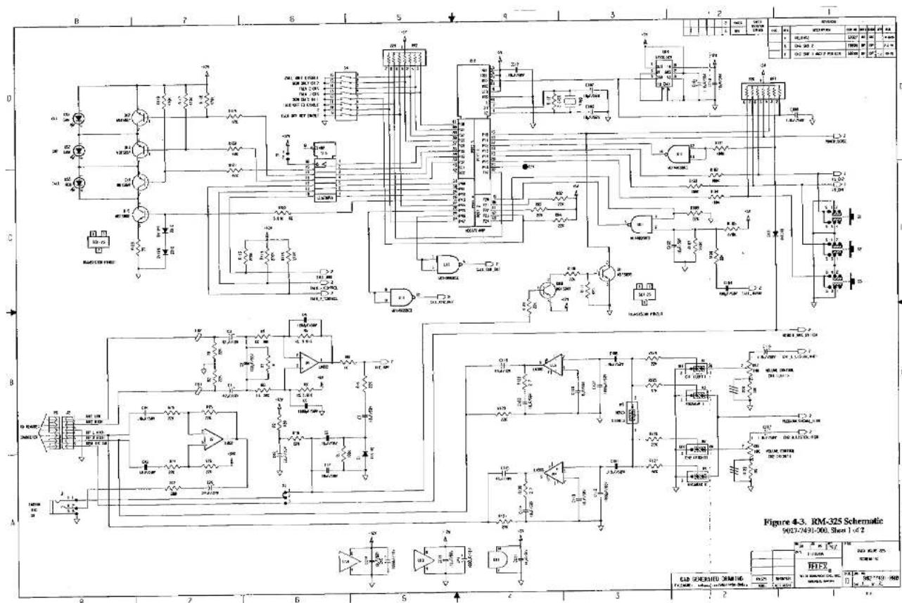
Figure 4-3. Schematic, Sheet 1, RM-325
9027-7491-000
Figure 4-4. Schematic, Sheet 2, RM-325


Figure 4-2. RM-325 PC Board Assembly 9050-745 -000


- Rack Mount Intercom Station
- PROPRIETARY NOTICE
- COPYRIGHT NOTICE
- WARRANTY NOTICE
- CUSTOMER SUPPORT
- RETURN SHIPPING INSTRUCTIONS
- SHIPPING TO THE MANUFACTURER
- TABLE OF CONTENTS
- SECTION 1: DESCRIPTION AND SPECIFICATIONS
- DESCRIPTION
- GENERAL
- FEATURES
- CONNECTIONS & CONTROLS
- SPECIFICATIONS
- SYSTEM SPECIFICATIONS
- GENERAL SPECIFICATIONS
- INTERFACE REQUIREMENTS
- RTS™ Intercom Channel:
- Program Input:
- Current Source:
- HEADPHONE AMPLIFIER
- Voltage Gain:
- Maximum Output:
- Frequency Response:
- Output Voltage Level:
- Headphone Impedance:
- Sidetone:
- MICROPHONE PREAMPLIFIER
- Maximum Voltage Gain:
- Input Impedance:
- Limiter Range:
- Total Harmonic Distortion:
- CONNECTOR PIN CONFIGURATIONS
- Headset Connector
- Intercom Line Input Connector
- Intercom Line Loop Connector
- Program Input Connector
- Auxiliary Inputs Connector
- RM-325 OPERATION
- Connecting a Headset
- Connecting To the Intercom Channels
- Adjusting the Sidetone
- Using the Momentary Mode to Make a Call
- Using the Latched Mode to Make a Call
- Receiving a Call
- Sending a Talk-Off Signal
- INTERNAL SWITCHES AND JUMPERS
- Intercom Audio Listen Option
- Program Input Audio Option
- Stereo/Mono Option
- Remote Mic Switch Option
- Momentary/Latched Talk Option
- Channel Talk Option
- Send Talk-Off Option
- Receive Talk-Off Option
- ALTERNATE POWERING METHODS
- One Channel Operation With a Non-RTS™ Power Supply
- Two Channel Operation With "Local Power"
- RTS™ Power Via Channel 2
- MOUNTING CONFIGURATIONS
- INSTALLATION GUIDELINES
- Choosing Headsets or Handsets
- Headphone Sound Isolation
- Isolation, Headset Microphones
- Cabling Requirements
- Wire Size
- Grounding
- Signal
- SECTION 3. REPLACEMENT PARTS
- WHERE TO OBTAIN PARTS
- SECTION 4. DIAGRAMS
Brand : RTS
Model : RM-325
Category : Intercom