
Wireless Optimizer - Network card / adapter ZYXEL - Free user manual and instructions
Find the device manual for free Wireless Optimizer ZYXEL in PDF.


| Product Type | Wireless Network Adapter / Card |
| Model | Wireless Optimizer |
| Brand | ZyXEL |
| Form Factor | USB 2.0/3.0 dongle |
| Dimensions (approx.) | 3.0 x 1.0 x 0.4 inches (7.6 x 2.5 x 1.0 cm) |
| Weight (approx.) | 0.4 oz (11 g) |
| Power Source | Powered via USB port (5V, 500mA) |
| Wireless Standards | IEEE 802.11 a/b/g/n/ac (dual-band 2.4GHz/5GHz) |
| Maximum Data Rate | Up to 867 Mbps (5GHz) / 300 Mbps (2.4GHz) |
| Security | WPA2, WPA3, WEP, 802.1X |
| Frequency Bands | 2.4 GHz / 5 GHz |
| Antenna | Internal dual-band antenna |
| Interface | USB 3.0 (backward compatible with USB 2.0) |
| Operating Systems Supported | Windows 10/11, macOS 10.12+, Linux |
| Temperature Range | 0°C to 40°C (32°F to 104°F) |
| Humidity | 10% to 90% non-condensing |
| Maintenance & Cleaning | Clean with a dry, soft cloth. Avoid liquids and abrasive cleaners. Store in a cool, dry place. |
| Safety Precautions | Do not expose to moisture or extreme temperatures. Use only with standard USB ports. Avoid physical shock. |
| Spare Parts & Repairability | No user-serviceable parts. Casing and PCB are not designed for repair. Replace device if faulty. |
| General Information | ZyXEL Wireless Optimizer is a compact USB Wi-Fi adapter designed to improve wireless connectivity on desktop and laptop computers. |
Frequently Asked Questions - Wireless Optimizer ZYXEL
User questions about Wireless Optimizer ZYXEL
0 question about this device. Answer the ones you know or ask your own.
Ask a new question about this device
Download the instructions for your Network card / adapter in PDF format for free! Find your manual Wireless Optimizer - ZYXEL and take your electronic device back in hand. On this page are published all the documents necessary for the use of your device. Wireless Optimizer by ZYXEL.
USER MANUAL Wireless Optimizer ZYXEL
ZyXEL Wireless Optimizer
Version 1.0.0
Edition 1, 12/2013
User's Guide
IMPORTANT!
READ CAREFULLY BEFORE USE.
KEEP THIS GUIDE FOR FUTURE REFERENCE.
Screenshots and graphics in this book may differ slightly from your screens due to differences in your computer operating system and web browser. Every effort has been made to ensure that the information in this manual is accurate.
Table of Contents
Part I: User's Guide .... 5
Chapter 1 Understanding the ZyXEL Wireless Optimizer....7
1.1 Overview ......7
1.1.1 Project Proposal and Planning Stage ....7
1.1.2 Adjustment after Deployment ....7
1.1.3 After-sales Maintenance 8
1.2 Features ....8
1.2.1 AP Planning ....8
1.2.2 Coverage Detection 8
1.2.3 Wireless Health Management ....8
1.3 System Requirement 9
1.4 Software Installation 9
Chapter 2 Tutorials....11
2.1 Working with the ZyXEL Wireless Optimizer User Interface 11
2.2 Working with the Site Map 12
2.2.1 Site Plan List 12
2.2.2 Site Information 14
2.3 Working with the Access Points ....14
2.3.1 AP Planning Tool 14
2.3.2 AP List Window 15
2.3.3 AP Options 17
2.4 Connecting to the AC 18
2.4.1 AC Options 18
2.4.2 AC Connection Settings 20
2.5 Using Options and Help 21
2.5.1 Preferences ....23
2.6 Planning AP and Associating AP with the AC 23
2.6.1 Procedure ...... 23
2.6.2 Successful Association 25
Part II: Technical Reference....27
Chapter 3 AP Planning & Deployment Guide ....29
3.1 WiFi Overview 29
3.1.1 WiFi Speed 31
3.1.2 WiFi Speed v/s. Coverage and Capacity 31
3.1.3 Multicast Transmission Conditions ...... 33
3.2 Concept of AP Deployment .... 33
3.2.1 TX Power 33
3.2.2 Channel Planning and Bandwidth Consideration .... 35
3.2.3 Antenna Effect ...... 37
3.2.4 Attenuation 37
3.2.5 Interference 38
3.3 AP Deployment Considerations .... 38
3.3.1 Location 38
3.3.2 Coverage purpose .... 38
3.3.3 Capacity purpose .... 39
3.3.4 Roaming 39
Chapter 4 Troubleshooting....41
4.1 AP Planning 41
4.2 Correlating AP to AC 47
4.3 Error Notifications Concerning AC 53
4.4 Setting Site Info and Preferences ....54
Appendix A Legal Information....56
Index 58
PART I
User's Guide
Understanding the ZyXEL Wireless Optimizer
1.1 Overview
This chapter introduces the main features, functions and applications of ZyXEL Wireless Optimizer.
The ZyXEL Wireless Optimizer is a practical, effective and easy-to-use tool that helps you with many networking tasks, ranging from organizing wireless networks to monitoring network performance.
The ZyXEL Wireless Optimizer builds planning maps by utilizing RF signals, information gathered from the deployed APs and the NXC2500 WLAN controller; none of these require costly on-site survey tools, additional sensors or location servers. The ZyXEL Wireless Optimizer provides a visualization of the network performance on a wireless network site map. This helps gauge the functioning of the network. Taking advantage of the RF coverage and health data provided by the ZyXEL Wireless Optimizer, network administrators will be able to address network problems quickly. This will improve the quality of services provided and thereby, help optimize your wireless network.
1.1.1 Project Proposal and Planning Stage
When proposing a wireless network deployment project, the first question that a network architect should tackle is the number of access points required. With the help of the ZyXEL Wireless Optimizer, you can estimate the required quantity by placing the access points onto the site map. This tool also provides some advanced user-scenario options, such as high-density areas; it also provides different environments such as office or hotel. All that is left to be done is simply select those options that more most relevant to the conditions expected in a real-time situation. Based on the information provided, the ZyXEL Wireless Optimizer will calculate the total coverage that will be provided by the selected APs. Thanks to ZyXEL Wireless Optimizer, the network architect can plan and simulate the types of access points required for the deployment with great ease.
1.1.2 Adjustment after Deployment
It is a common knowledge among network administrators that traditional wireless LAN deployments are extremely time-consuming and labor-intensive. Furthermore, they usually cannot be completed in one visit. To address this major concern, the ZyXEL Wireless Optimizer has been designed to reduce both time and costs by planning wireless networks with the help of network simulation, before their actual deployments.
Once the NXC2500 WLAN controller and NWA access points are deployed at the desired positions and switched on, the network administrator can use the ZyXEL Wireless Optimizer to review the actual signal coverage map. This is done with the help of the data collected using RF signals from the controller and access points. In addition, this convenient tool will allow the administrator to
move or add access points for eliminating any possible dead spots and adjusting the output power level to prevent any possible signal interference on the NXC controller.
1.1.3 After-sales Maintenance
Nowadays, most network administrators use either the controller user interface or SNMP-based network management systems to monitor and manage their deployed networks. The network administrators find it very difficult to quickly identify and locate the device in question on the network due to the commonly used list view. In addition to providing a comprehensive picture of the network devices on the site map, the ZyXEL Wireless Optimizer offers network administrators another significant benefit by visualizing key performance details such as the channel in use, transmit retry rate and frame error rate. The network status is presented in a user-friendly manner, with all the critical information collated at one place. This helps network administrators save time and speedily address network issues, thereby improving the quality of services provided.
1.2 Features
The three major functions of the ZyXEL Wireless Optimizer are:
- AP Planning
• Coverage Detection
• Wireless Health Management
Let's understand the inherent features of each of these functions of the ZyXEL Wireless Optimizer.
1.2.1 AP Planning
ZyXEL Wireless Optimizer offers the following features for AP planning:
• A free standalone planning tool
- No requirement of any additional dedicated sensors, exciters or location servers
- Accurate estimation of the quantity and deployment of APs
1.2.2 Coverage Detection
ZyXEL Wireless Optimizer offers the following features for network coverage detection:
- One-click calculation or recalculation of coverage map with real-time data feed from the wireless LAN infrastructure
- Proactive RF parameter adjustments for simulating the best case scenarios of the network coverage and performance
1.2.3 Wireless Health Management
ZyXEL Wireless Optimizer offers the following features for wireless health management:
- Visualized device location for troubleshooting, planning and asset tracking
- Practical, essential RF statistics shown on the map, including information such as Channel in use, Stations counts, TX Retry rate and RX frame error rate
1.3 System Requirement
Prior to installing ZyXEL Wireless Optimizer, please ensure that your system meets the specifications listed below:
Operating System
• Microsoft Windows platform
• Windows XP Professional SP2+
- Windows Vista (32-bit)
• Windows 7 (32-bit, 64-bit)
• Windows 8 (32-bit, 64-bit)
Processor
- Intel Pentium 4 1.4GHz or higher recommended
RAM
- 2 GB recommended
Disk Space
• 100 MB of free disk space
Map Image Format
- Supported formats include .bmp, .gif, .jpg, .png
1.4 Software Installation
The ZyXEL Wireless Optimizer is green software and a portable application. This is due to the fact that the application can be executed even with a removable media without installation. The installation wizard offers a convenient way for the user to install or uninstall this software. The installation process will not maintain additional records in the operating system, and it doesn't require any additional library. You can also copy the ZyXEL Wireless Optimizer directory, reproduce it in another location in your device and run the software without any glitches.
Tutorials
This chapter provides tutorials for ZyXEL Wireless Optimizer as follows:
• Working with the ZyXEL Wireless Optimizer User Interface
• Working with the Site Map
• Working with the Access Points
- Connecting to the AC
• Using Options and Help
- Planning AP and Associating AP with the AC
2.1 Working with the ZyXEL Wireless Optimizer User Interface
You will see the following UI when running the ZyXEL Wireless Optimizer for the first time.
Figure 1 ZyXEL Wireless Optimizer 1.0 > ZyXEL Wireless Optimizer User Interface
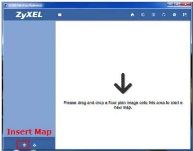
You can toggle the left and right side bars, if required. There are two ways to start a new map for a given floor plan:
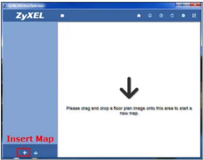
- Drag and drop a floor plan image in the workspace.
OR
- Click the Insert Map function on the left side bar. The Open dialog box is displayed.
- Select the required floor plan and click OK. The floor plan is displayed in the workspace.
After inserting the image of the floor plan, the workspace will look as shown in the illustration.
Figure 2 ZyXEL Wireless Optimizer 1.0 > ZyXEL Workspace
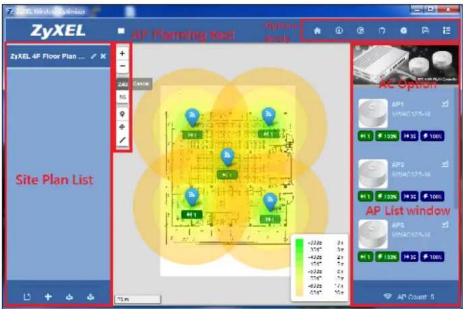
As displayed in the illustration, the Wireless Optimizer User Interface consists of five sections, namely:
- Site Plan List
- AP Planning Tool
- AP List Window
- AC Option
- Options and Help
Let's understand the functioning of each of these aforementioned sections.
2.2 Working with the Site Map
The Site Plan List section will display a set of site plans for a particular building. In this section, you can arrange different site plans for different floors within the same building.
2.2.1 Site Plan List
The Site Plan List section includes the following functions:
Figure 3 ZyXEL Wireless Optimizer 1.0 > Site Plan List > Functions
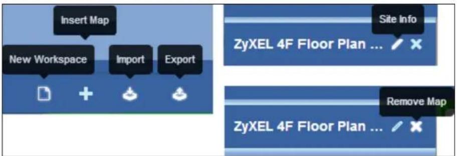
- New Workspace - You can clear all existing floor plan lists and start a new floor plan.
- Insert Map - You can insert the image of a new floor map.
- Import - You can import a floor plan from an existing file (.ZWO). The current floor plan will be overwritten and replaced by the imported file.
- Export - You can export the current floor plan to another file for backup or storage purposes.
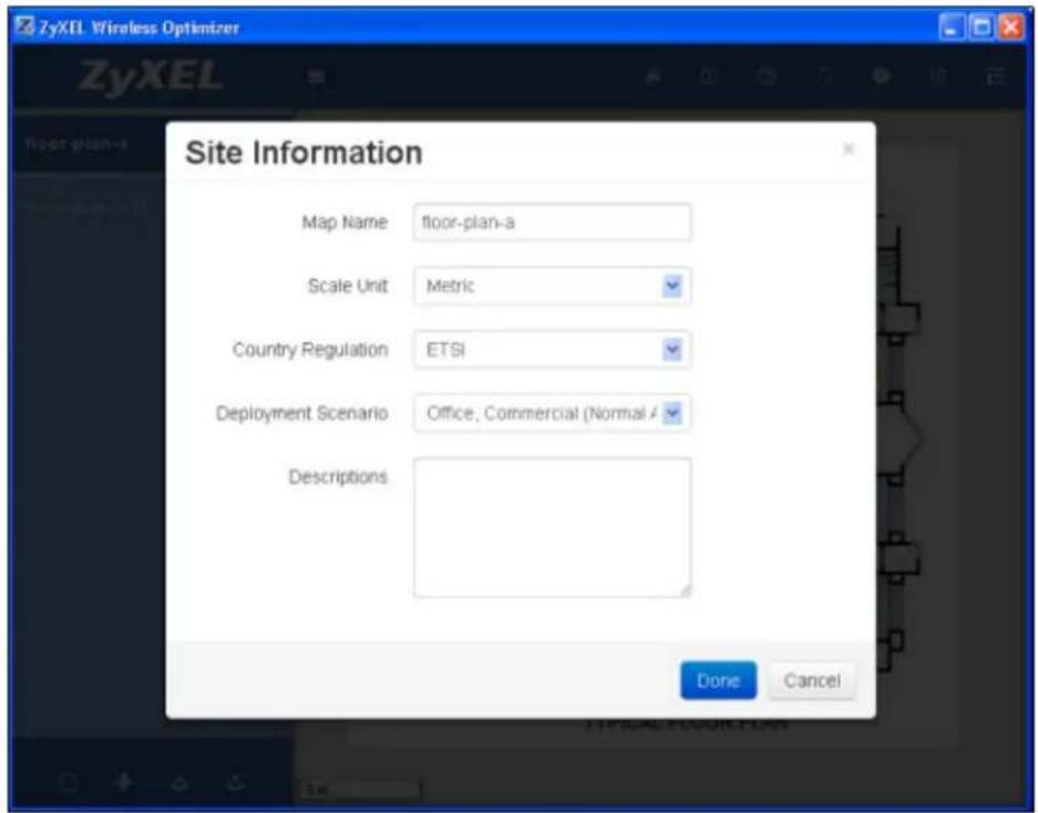
- Site Info - You can edit the details of the current floor plan. Clicking this function will display the Site Information pop-up box, as shown in the illustration.
Figure 4 ZyXEL Wireless Optimizer 1.0 > Site Plan List > Site Info
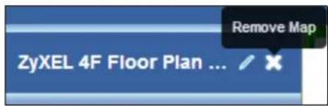
- Remove Map - You can remove the required site map.
2.2.2 Site Information
The Site Information pop-up box contains numerous editable fields, which have been tabulated below.
Table 1 ZyXEL Wireless Optimizer 1.0 > Site Plan List >Site Info
| LABEL DESCRIPTION | |
| Map Name This field displays the title of the current site map. You can edit the name of the site map. | |
| Scale Unit This field displays the default unit of measurement. You can change the scalable unit for the site map from Metric to Imperial and vice versa. | |
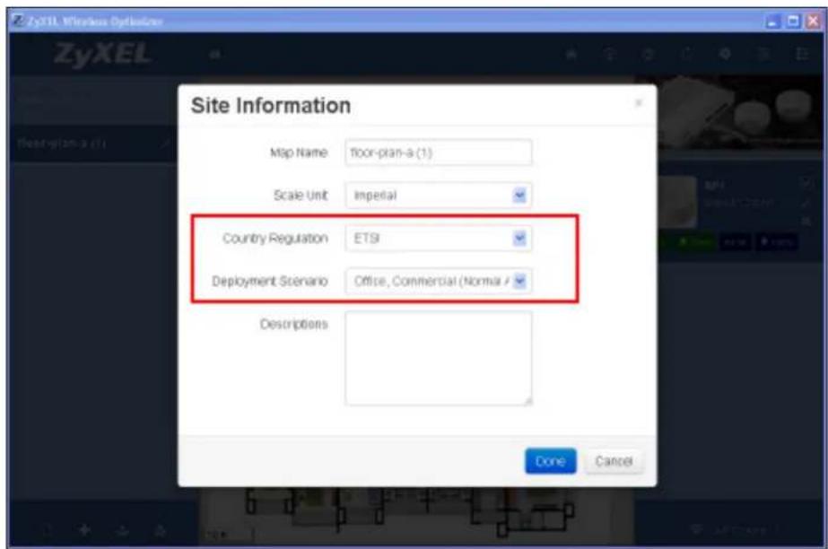
| Country Regulation This field displays the default country regulation details. You can change the country regulations for the site map from ETSI to FCC and vice versa. | |
| Deployment Scenario This field displays the default AP deployment scenario for setting attenuation values. You can change the deployment scenario for the site map from Office, Commercial (Normal Attenuation) to Home, Hospitality (High Attenuation) and vice versa. | |
| Descriptions This field is an open-text field that displays additional information on the site map. You can a description for the site map, if needed. | |
| Done Click this button to incorporate all changes made in the Site Information pop-up box. | |
| Cancel Click this button to discard the changes made and reset the information present in the Site Information pop-up box. | |
2.3 Working with the Access Points
2.3.1 AP Planning Tool
The AP Planning Tool section will display a toolbar consisting of the following functions:
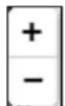
- Adjust Viewing Scale - You can use the + (Zoom In), - (Zoom Out) buttons to adjust the viewing scale on the map. Alternatively, you can adjust the viewing scale by scrolling your mouse wheel.
Figure 5 ZyXEL Wireless Optimizer 1.0 > AP Planning Tool > Zoom In & Zoom Out
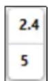
- Radio Coverage - You can select deploy the AP for either 2.4 Ghz or 5 Ghz of radio coverage, as per your requirement.
Figure 6 ZyXEL Wireless Optimizer 1.0 > AP Planning Tool > Radio Coverage Options
- Deploy AP - You can add the access point to the floor plan.
Figure 7 ZyXEL Wireless Optimizer 1.0 > AP Planning Tool > Deploy AP

- Relocate AP -You can move the access point from its original location to any other location on the floor plan.
Figure 8 ZyXEL Wireless Optimizer 1.0 > AP Planning Tool > Relocate AP

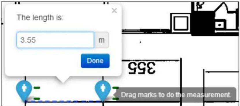
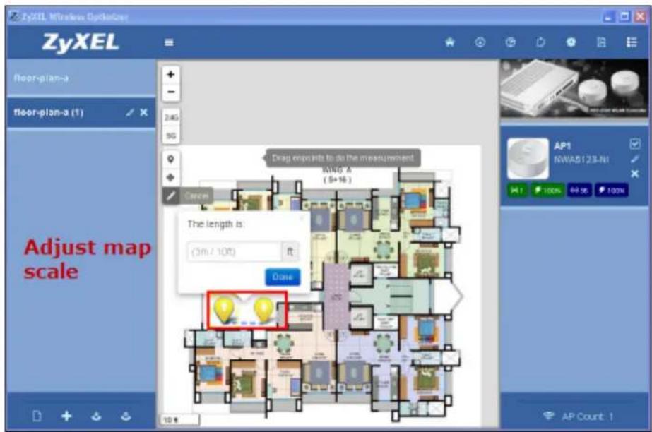
- Unit Measuring - You can adjust the distance between two access points deployed on a floor plan. The unit of measurement is meters (m) if the Scale Unit chosen is Metric. On the other hand, the unit of measurement is feet (ft) if the Scale Unit chosen is Imperial.
Figure 9 ZyXEL Wireless Optimizer 1.0 > AP Planning Tool > Unit Measuring
2.3.2 AP List Window
The AP List Window section will display details of all the APs on the site map. You can adjust various settings such as the AP model, channel or power setting during planning stage; these settings can also be synced when the network connection to AC controller is available.
The AP List Window section includes the name of current AP model and provides a quick view of the various AP parameters. Other functions available include:
- Hide - You can hide an access point from the site map by clicking the Hide icon.
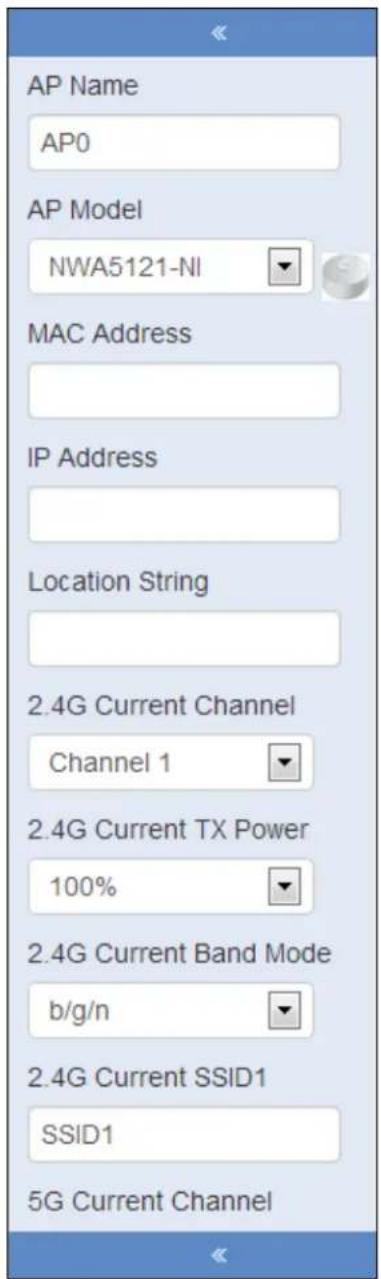
- AP Options - Clicking the AP Options button displays details. These include AP name and model, MAC and IP addresses, location string, current channel, and TX power for 2.4G and 5G coverage, additional attenuation such as number of concrete walls or compartments.
Figure 10 ZyXEL Wireless Optimizer 1.0 > AP List Window > AP Options
- Remove AP - You can delete an access point by clicking Remove AP icon.
Figure 11 ZyXEL Wireless Optimizer 1.0 > AP List Window > Remove AP
2.3.3 AP Options
The AP Options pop-up box contains numerous editable fields, which have been tabulated below.
Table 2 ZyXEL Wireless Optimizer 1.0 > AP List Window > AP Options
| LABEL DESCRIPTION | |
| AP Name This field displays the name of the access point that has been deployed on the site map. You can edit the AP name. | |
| MAC Address This field displays the MAC address of the access point that has been deployed on the site map. You can edit the MAC Address. | |
| IP Address This field displays the IP address of the access point that has been deployed on the site map. You can edit the IP Address. | |
| Location String This field displays the location string of the access point that has been deployed on the site map. You can edit the location string. | |
| AP Model This field displays the type of the access point that has been deployed on the site map. You can edit the AP Model. | |
| 2.4G | |
| Current Channel This field displays the current channel used for 2.4G coverage. You can edit the 2.4G current channel. | |
| Current TX Power This field displays the current TX power used for 2.4G coverage. You can edit the 2.4G current TX power. | |
| Current Band Mode This field displays the current band mode used for 2.4G coverage. You can edit the 2.4G current band mode. | |
| 5G | |
| Current Channel This field displays the current channel used for 5G coverage. You can edit the 5G current channel. | |
| Current TX Power This field displays the current TX power used for 5G coverage. You can edit the 5G current TX power. | |
| Current Band Mode This field displays the current band mode used for 5G coverage. You can edit the 5G current band mode. | |
| Evaluate the Attenuation | |
| Type of First Wall | This field includes a drop-down list containing different types of wall. Examples include solid wall and partition wall. You can edit the type of the first wall. |
| Distance of First Wall to AP | This field displays the total distance between the access point and the first wall. You can edit the distance of first Wall to AP. |
| Type of Second Wall | This field includes a drop-down list containing different types of wall. Examples include solid wall and partition wall. You can edit the type of the second wall. |
| Distance of Second Wall to First Wall | This field displays the distance between the first and the second wall. You can edit the distance of second wall to first wall. |
| High Density Area? | Check this field if the area where the access point has been deployed is a high density area. A red mark will appear inside the blue AP icon. |
| Consider Client Limitation? | Check this field if the client power limitation needs to be considered. The default Client output power is 15dBm with 0 dBi antenna. |
Table 2 ZyXEL Wireless Optimizer 1.0 > AP List Window > AP Options
| LABEL DESCRIPTION | |
| Placement Height This field displays the required height of the AP deployed. You can edit the placement height. | |
| Notes This field is an open-text field that displays additional information on the AP. You can add notes, if required. | |
2.4 Connecting to the AC
2.4.1 AC Options
The AC Options section consists of two functions, namely:
- Connection Settings - You can edit the connection settings.
Figure 12 ZyXEL Wireless Optimizer 1.0 > AC Options > Connection Settings
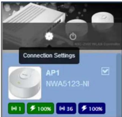
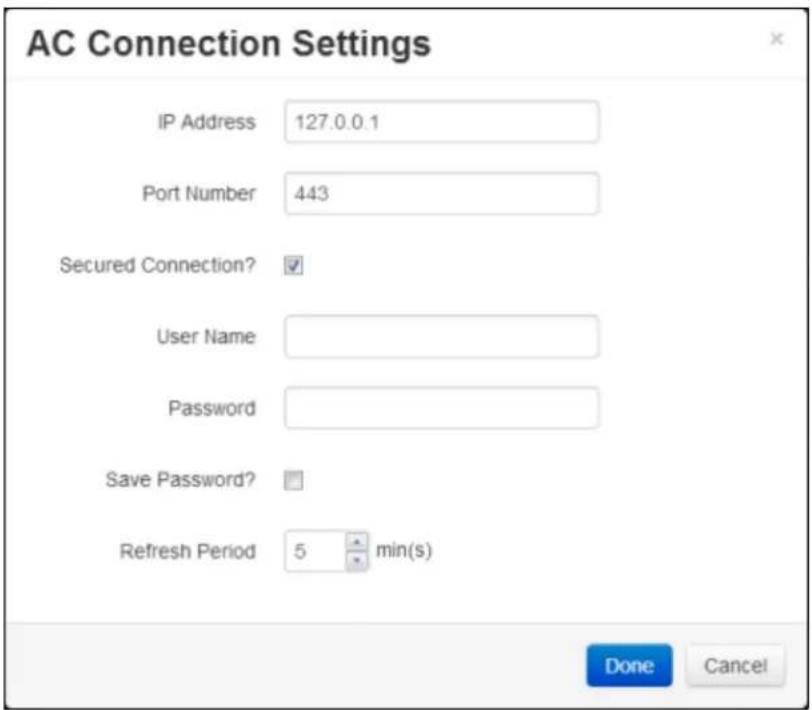
Clicking this icon will display the AC Connection Settings pop-up box that contains numerous functions such as IP address, Port (80/443), secure connect, user name/password, and refresh period.
Figure 13 ZyXEL Wireless Optimizer 1.0 > AC Options > Connection Settings
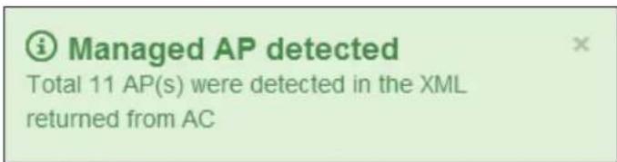
- Connect - You can connect to AC. After successfully connecting to AC, the following information will be displayed at the bottom.
Figure 14 ZyXEL Wireless Optimizer 1.0 > Successful Connection
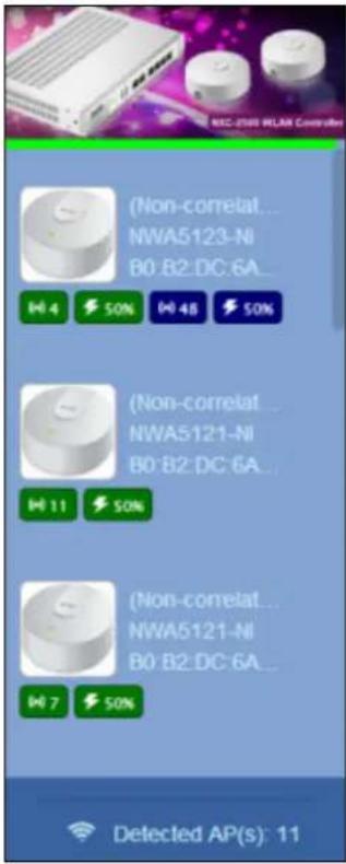
The AP list windows retrieved from AC will appear as illustrated below.
Figure 15 ZyXEL Wireless Optimizer 1.0 > AP List Windows
2.4.2 AC Connection Settings
The AC Connection Settings pop-up box contains numerous editable fields, which have been tabulated below.
Table 3 ZyXEL Wireless Optimizer 1.0 > AC Connection Settings
| LABEL DESCRIPTION | |
| IP Address This field displays the IP address of the access point that has been deployed on the site map. You can edit the IP address settings to AC. | |
| Port Number This field displays the port number of the access point deployed on the site map. You can edit the port number settings to AC. The default is 80 for a non-secured http connection and 443 for secured https connection. | |
| Secured Connection Check this field to enable secured connection settings to AC. | |
| Username This field displays the username of the AC connection. You can edit the username to connect AC. | |
| Password This field displays the password of the AC connection. You can edit the password to connect AC. | |
| Save Password Check this field to save the password. The password is encrypted. | |
| Refresh Period This field displays the time duration in minutes, after which the AC data gets updated automatically. You can edit the refresh period value. | |
Table 3 ZyXEL Wireless Optimizer 1.0 > AC Connection Settings
| LABEL DESCRIPTION | |
| Done Click this button to | incorporate all changes made in the AC Connection Settings pop-up box. |
| Cancel Click this button to | discard the changes made and reset the information present in the AC Connection Settings pop-up box. |
2.5 Using Options and Help
The Options and Help section, illustrated below, will display the following functions:
Figure 16 ZyXEL Wireless Optimizer 1.0 > Options and Help Menu

• Home - You can view a blank workspace wherein you can import a new map.
- About - You can view the details on the software version and legal information concerning the software.
- User Guide - You can view the help file that will enable you to familiarize yourself with the software.
- Log Viewer - You can view or clear the log information.
- Preference - You can change the default settings of the software. Clicking this button will display the Preferences pop-up box, as illustrated below.
Figure 17 ZyXEL Wireless Optimizer 1.0 > Options and Help Menu > Preferences > General Tab
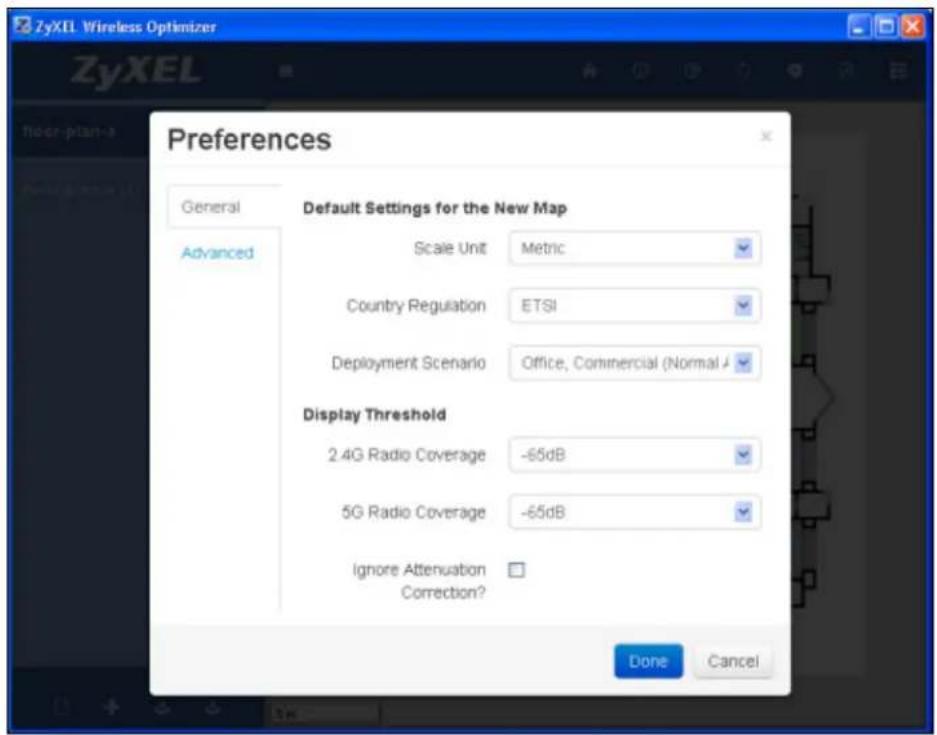
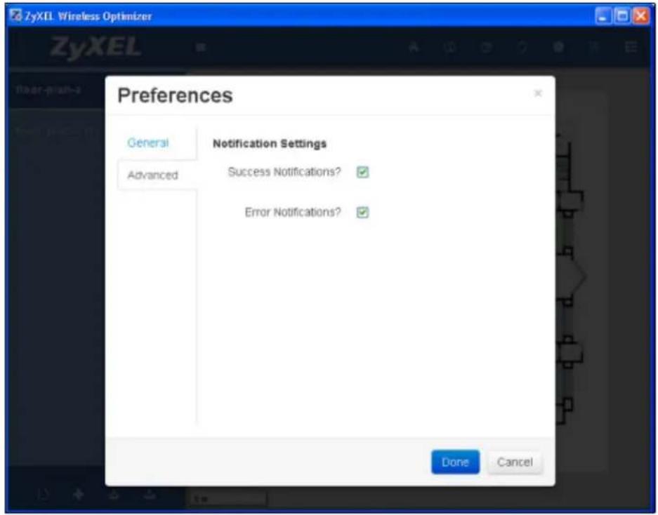
Figure 18 ZyXEL Wireless Optimizer 1.0 > Options and Help Menu > Preferences > Advanced Tab
- PDF Export - You can export the current screen displaying the floor plan to a PDF file. Currently, the PDF generated supports only single byte text.
- Toggle AP List - You can toggle the AP List Window.
2.5.1 Preferences
The Preferences pop-up box contains numerous editable fields, which have been tabulated below.
Table 4 ZyXEL Wireless Optimizer 1.0 > Options and Help Menu > Preferences
| LABEL DESCRIPTION | |
| General | |
| Default Setting for the New Map | |
| Scale Unit This field displays the default unit of measurement. You can change the default scale unit settings for the new map. | |
| Country Regulation This field displays the default unit of measurement. You can change the default settings of this field for the new map. | |
| Deployment Scenario This field displays the default AP deployment scenario for setting attenuation values. You can change the default settings of this field for the new map. | |
| Display Threshold | |
| 2.4G Radio Coverage This field includes a drop-down list containing various 2.4G coverage values. You can change the default 2.4G radio coverage settings for the coverage drawing. | |
| 5G Radio Coverage This field includes a drop-down list containing various 5G coverage values. You can change the default 5G radio coverage settings for the coverage drawing. | |
| Ignore Attenuation Correction? | Check this field to ignore attenuation correction. Due to this action, the coverage circle radius will be fixed to the display threshold setting and only change the color inside the circle, if there is any additional attenuation.If you clear this field, the coverage circle radius will be changed according to display threshold setting, if there is any additional attenuation. |
| Advanced | |
| Notification Settings | |
| Success Notifications? Check this field to enable the Success Notifications pop-up message. | |
| Error Notifications? Check this field to enable the Error Notifications pop-up message. | |
| Done | Click this button to incorporate all changes made in the Preferences pop-up box. |
| Cancel Click this button to discard the changes made and reset the information present in the Preferences pop-up box. | |
2.6 Planning AP and Associating AP with the AC
2.6.1 Procedure
Associating the planning AP with the AP list retrieved from the AC involves the following steps:
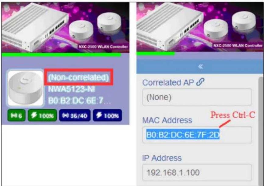
- Map the MAC address of the AP on the map. This can be obtained by clicking the AP Options icon.
- Connect with the AC controller and get the AP on the AC.
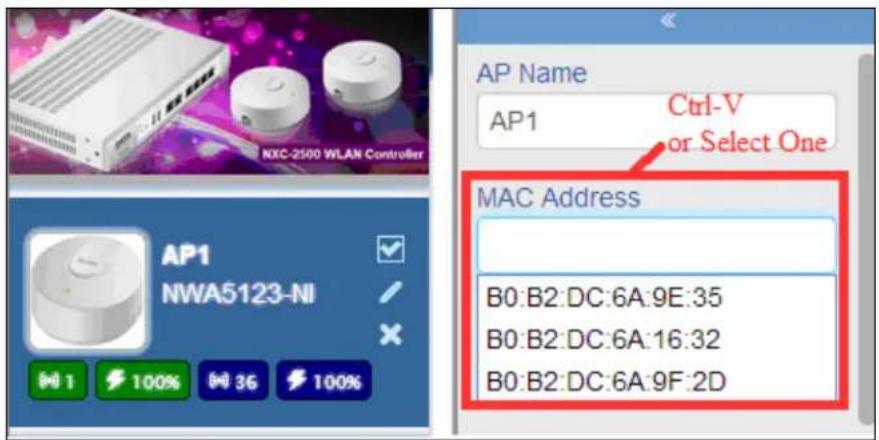
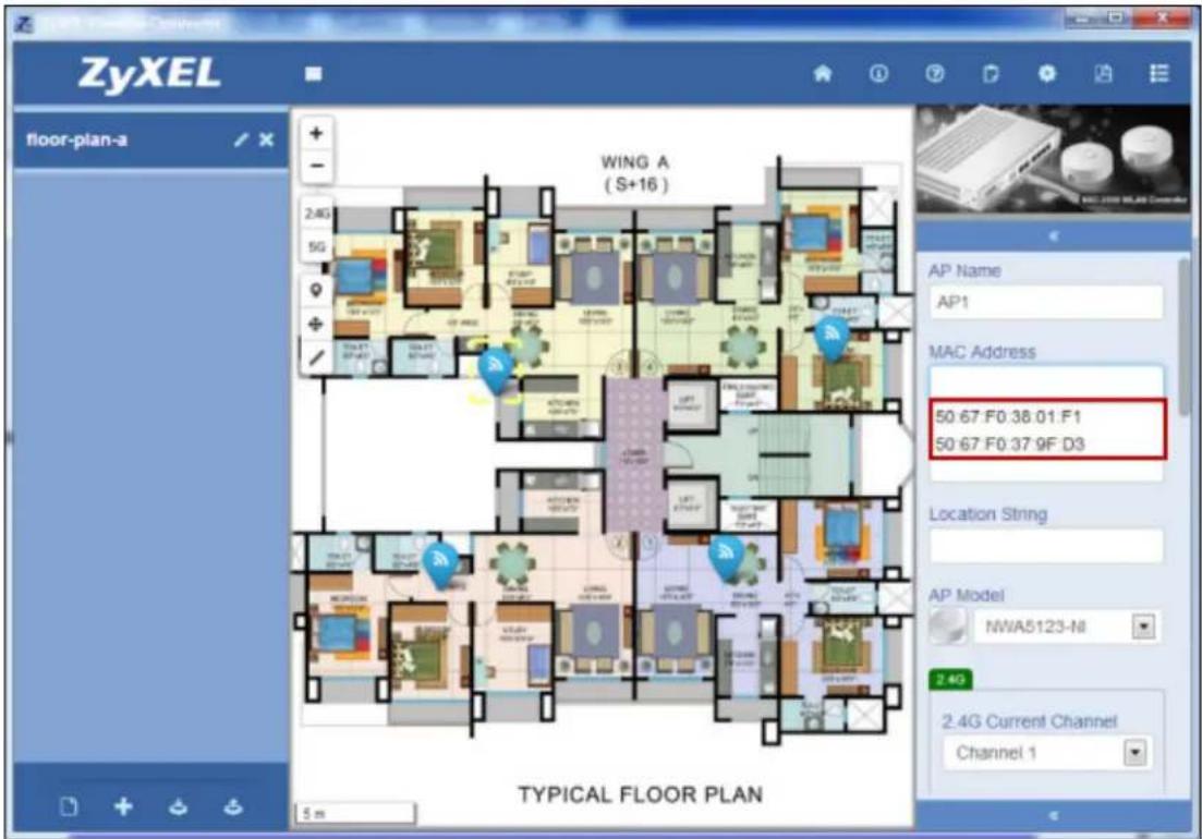
- Select one MAC address from the MAC Address drop-down list. Ensure that you retain the selected MAC address by copying it.
Figure 19 ZyXEL Wireless Optimizer 1.0 > AP Options > MAC Address
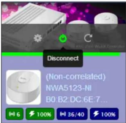
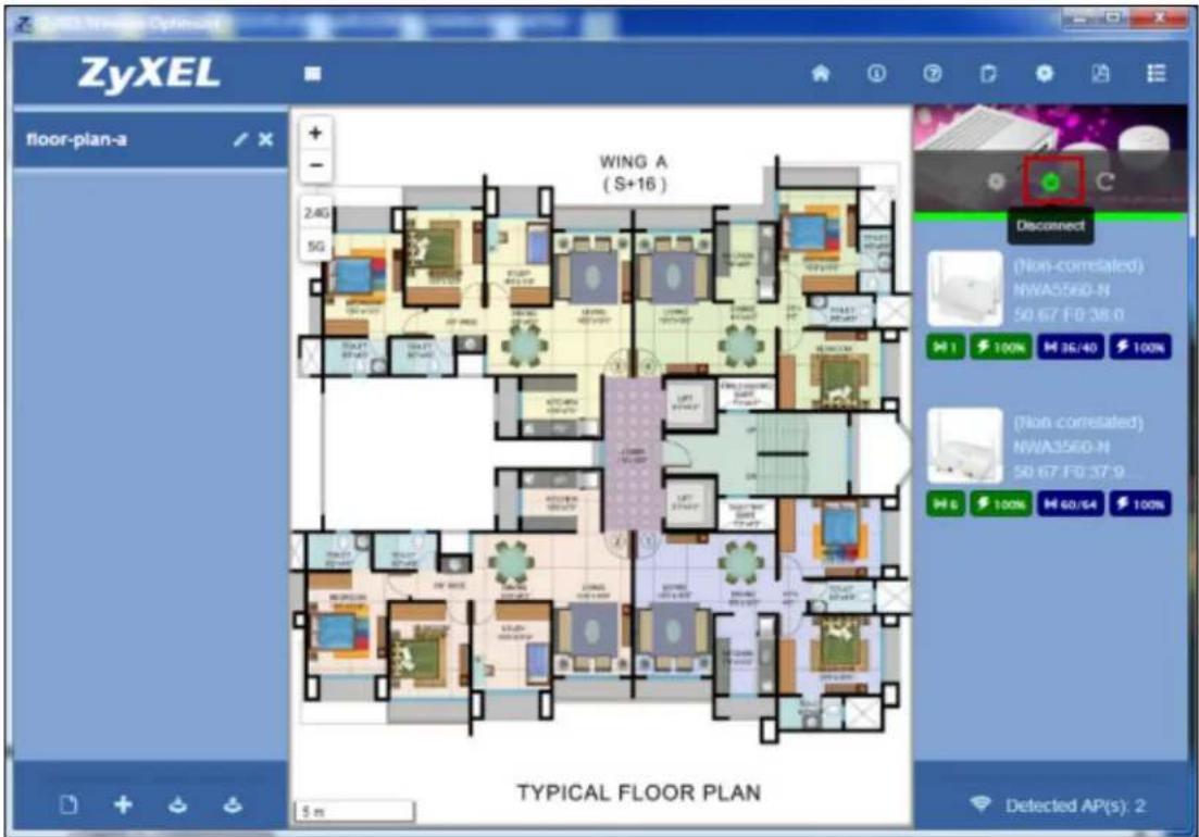
- Disconnect the AC by clicking the Disconnect icon from the AC Options menu.
Figure 20 ZyXEL Wireless Optimizer 1.0 > AC Options > Disconnect
- Select a MAC address from drop-down list. Alternatively, you can paste the MAC address that was copied earlier, belonging to the AP on the floor plan.
Note: You can refresh the data collected from AC by clicking the Refresh icon from the AC Options menu.
Figure 21 ZyXEL Wireless Optimizer 1.0 > AP Options > MAC Address
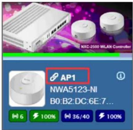
- Reconnect with the AC controller. The current AP, whose MAC address was used in this process, is now correlated to the AP on the AC.
Figure 22 ZyXEL Wireless Optimizer 1.0 > AP List Window
2.6.2 Successful Association
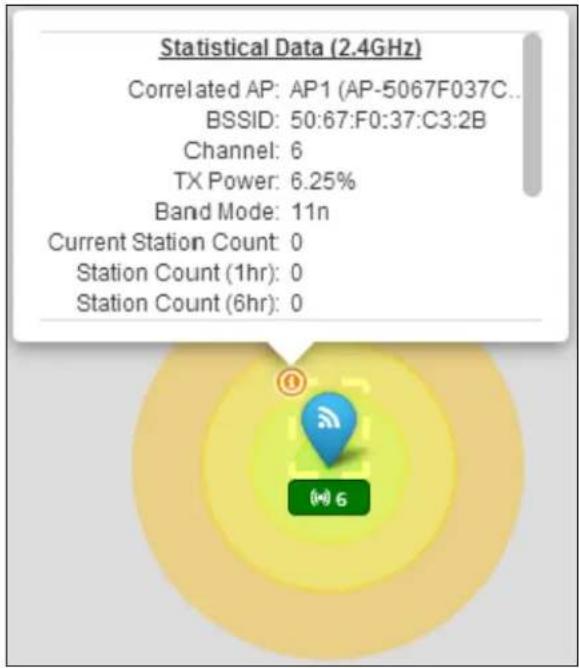
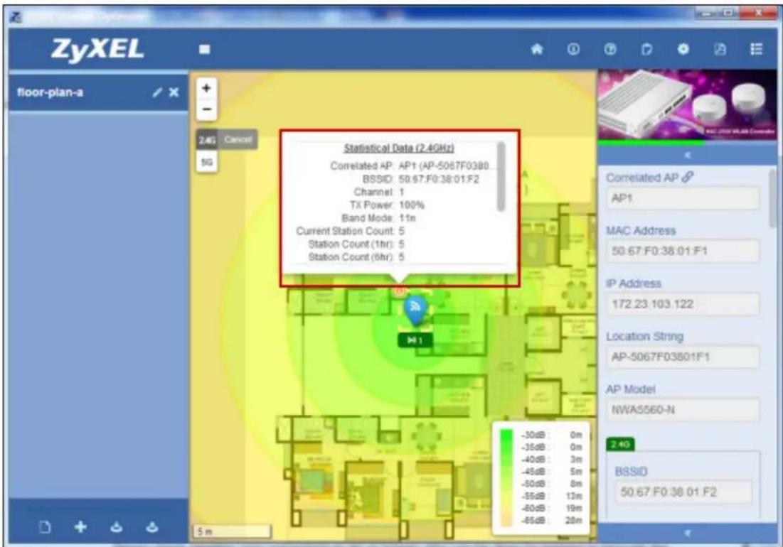
When the AP has been successfully associated, the statistic and information pertaining to that AP will be retrieved and periodically updated from AC site. These details will be displayed on the site map or AP list window.
Figure 23 ZyXEL Wireless Optimizer 1.0 > Workspace > AP > Statistics of a Successfully Associated AP
PART II
Technical Reference
AP Planning & Deployment Guide
This chapter introduces the basic principles of WiFi, which are essential in the understanding of AP deployment. The chapter then elaborates on AP planning and specifies the various factors to be considered before the deployment of AP.
3.1 WiFi Overview
The IEEE 802.11 standards define WiFi as the technology that allows the electronic devices to connect and exchange data in a wireless local area network. WiFi technology operates in unlicensed frequency bands such as 2.4GHz or 5GHz and provides various types of connections such as device to device or multi-device to access point. In the present scenario, consumer electronic devices such as personal computers, notebooks and smart phones use WiFi to connect to network access points. In some cases, they directly connect with other devices through valuable shared unlicensed frequency bands. The WiFi standard defines over 11 channels in the 2.4GHz range and over 20 channels in the 5GHz range.
Unlike the wired Ethernet connection, WiFi connection is through the space. Yet, even messages transmitted wirelessly can be intercepted and hence, WiFi also needs secured encryption protocols such as WPA/WPA2 protocols, which are the most commonly used network security protocols nowadays. To adapt the existing Ethernet mechanism to wireless transmission, the WiFi devices use a CSMA/CA (Carrier Sense Multiple Access with Collision Avoidance) mechanism since collision detection cannot be done on a wireless transmission.
WiFi technology uses the same channel to transmit and receive; as a result, to avoid interference with other devices in a channel, only one device can transmit or receive at a specified time. A random number series is applied from AP to each device to ensure that all devices have nearly the same probability to access the air resource. Until recently, the WMM (Wireless Multimedia Extensions) mechanisms were defined, which could fine-tune this random number series to the timing of critical multimedia devices with a higher access probability.
Simply put, the WiFi access point topology is similar to the old wired half-duplex Ethernet hub.
Figure 24 WiFi Access Point Topology
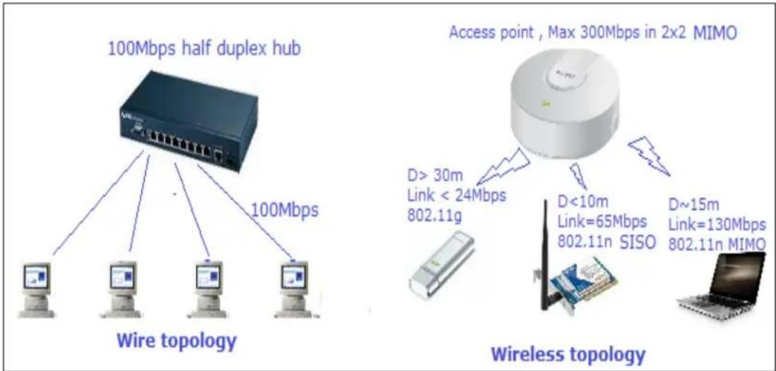
However, unlike the wired Ethernet hub topology, the wireless topology exhibits the following differences:
- The maximum performance is related to the AP specifications, for example, theoretically, a 2x2 MIMO 802.11n connection can transmit up to a network speed of 300Mbps with a 40MHz bandwidth and about 2/3 of the total time used for data transmission.
- The AP can have two radio paths, and it can perform like two independent virtual hubs.
- The Station link speed in TX (transmit) and RX (receive) directions is different and changes with respect to the station capability, distance and environment status.
- When the station number is increased, the probability of collision is also increased. This, in turn, significantly reduces the overall performance and throughput; the collision penalty in this scenario is also much more serious than in case of the wired situation.
- Interference from other devices will decrease the overall performance. Also, it takes a lot of time for re-transmission of data. However, this is unavoidable since WiFi operates in an unlicensed band and shares resources with other devices equally.
- Each device has nearly equal probability for network access; however, the WMM function can prioritize the devices.
- The total throughput and capacity is determined by a summation of the air resources used by all stations in a given period of time. A slower device that operates for a long distance or has a lower capability (for example, 802.11b) will significantly reduce the total capacity due to lower air resource usage efficiency.
The exhibition of the above-mentioned behavior makes it hard to define the real capacity and coverage of a WiFi access point since it depends on a lot of unpredictable factors. In addition to these, it also includes the probability effect, which makes it even harder to define.
A simple rule of thumb is that a single wireless access point can cover an area with a radius of up to 20m\~30m in an indoor environment and provide a good signal for around 20\~30 stations, with each radio engaging in bi-directional transmission. However, this is a crude estimate without considering factors such as the station capability, distance, and environment elements such as concrete wall or interference.
3.1.1 WiFi Speed
The IEEE 802.11 wireless standard defines a lot of characteristics of the WiFi mode; one of which is the maximum link speed, illustrated below.
Figure 25 Maximum Link Speed
| MCS Index | Number of spatial streams | Modulation (All Stream) | Coding rate | Data Rate (in Mbps) (GI = 800ns) | Data Rate (in Mbps) (GI = 400ns) | Receive sensitivity | |||
| 20MHz | 40MHz | 20MHz | 40MHz | 20MHz | 40MHz | ||||
| 0 | 1 | BPSK | 1/2 | 6.5 | 13.5 | 7.2 | 15 | -82 | -79 |
| 1 | 1 | QPSK | 1/2 | 13 | 27 | 14.4 | 30 | -79 | -76 |
| 2 | 1 | QPSK | 3/4 | 19.5 | 40.5 | 21.7 | 45 | -77 | -74 |
| 3 | 1 | 16-QAM | 1/2 | 26 | 54 | 28.9 | 60 | -74 | -71 |
| 4 | 1 | 16-QAM | 3/4 | 39 | 81 | 43.3 | 90 | -70 | -67 |
| 5 | 1 | 64-QAM | 2/3 | 52 | 108 | 57.8 | 120 | -66 | -63 |
| 6 | 1 | 64-QAM | 3/4 | 58.5 | 121.5 | 65 | 135 | -65 | -62 |
| 7 | 1 | 64-QAM | 5/6 | 65 | 135 | 72.2 | 150 | -64 | -61 |
| 8 | 2 | BPSK | 1/2 | 13 | 27 | 14.4 | 30 | -82 | -79 |
| 9 | 2 | QPSK | 1/2 | 26 | 54 | 28.9 | 60 | -79 | -76 |
| 10 | 2 | QPSK | 3/4 | 39 | 81 | 43.3 | 90 | -77 | -74 |
| 11 | 2 | 16-QAM | 1/2 | 52 | 108 | 57.8 | 120 | -74 | -71 |
| 12 | 2 | 16-QAM | 3/4 | 78 | 162 | 86.7 | 180 | -70 | -67 |
| 13 | 2 | 64-QAM | 2/3 | 104 | 216 | 115.6 | 240 | -66 | -63 |
| 14 | 2 | 64-QAM | 3/4 | 117 | 243 | 130.3 | 270 | -65 | -62 |
| 15 | 2 | 64-QAM | 5/6 | 130 | 270 | 144.4 | 300 | -64 | -61 |
| 16 | 3 | BPSK | 1/2 | 19.5 | 40.5 | 21.7 | 45 | -82 | -79 |
| 17 | 3 | QPSK | 1/2 | 39 | 81 | 43.3 | 90 | -79 | -76 |
| 18 | 3 | QPSK | 3/4 | 58.5 | 121.5 | 65 | 135 | -77 | -74 |
| 19 | 3 | 16-QAM | 1/2 | 78 | 162 | 86.7 | 180 | -74 | -71 |
| 20 | 3 | 16-QAM | 3/4 | 117 | 243 | 130 | 270 | -70 | -67 |
| 21 | 3 | 64-QAM | 2/3 | 156 | 324 | 173.3 | 360 | -66 | -63 |
| 22 | 3 | 64-QAM | 3/4 | 175.5 | 364.5 | 195 | 405 | -65 | -62 |
| 23 | 3 | 64-QAM | 5/6 | 195 | 405 | 216.7 | 450 | -64 | -61 |
For obtaining the maximum link speed, a -65 dBm signal strength is recommended, since other physical effects such as reflection, refraction or shadowing will reduce the signal strength.
3.1.2 WiFi Speed v/s. Coverage and Capacity
A relationship map depicting the link speed v/s. distance relationship is illustrated below.
Figure 26 Speed v/s. Distance
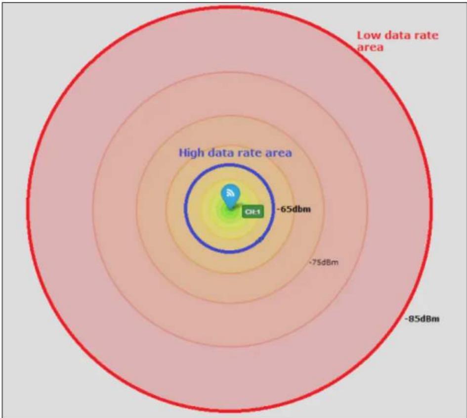
radar
| Category | Value | | ------------------ | -------- | | High data rate area | -65dbm | | Low data rate area | -85dbm |When the deployment scenarios select maximum converge, the situation requires the network AP to meet the low rate condition in most areas and reduce the capacity.
In a low rate weak signal area, clients can be easily interfered by other strong signal APs/clients, but the co-channel interference between deployed APs (TX direction) and clients (RX direction) is decreased due increased distances.
When the deployment scenarios select the maximum capacity, the situation has to meet with high rate conditions and reduce the coverage. Although it won't be easily interfered by other APs/clients, the co-channel interference between deployed APs and clients will still be increased significantly. In such cases, the interference between clients will become serious and unavoidable.
Note that the maximum coverage area is decided by the minimum conditions that exist between the APs and clients as they do not have equal link capabilities.
A simple rule of thumb is to maintain a distance of at least 20m radius between the wireless access points for capacity and at least 30-50m for coverage in a normal indoor environment. However, this is a crude estimate without considering factors such as the station capability, distance, and environment elements such as concrete wall or other running software applications.
3.1.3 Multicast Transmission Conditions
In some rare multicast transmission deployment scenario such as streaming to multiple devices, the general rule of thumb is to maintain all the devices in a high rate area, so that all of these devices receive good signal quality for the required rate of streaming. When one or all of the devices are outside the high data rate area, the multicast to unicast option can help, however, a trade off may be required to reduce the streaming rate due to reduction of the total capacity.
3.2 Concept of AP Deployment
Before commencing the study on various factors to be considered for WiFi deployment, it is essential to be acquainted with a few concepts. These include:
- Tx Power
• Channel Planning and Bandwidth Consideration - Antenna Effect
- Attenuation
- Interference
Let's understand each of these concepts in the subsequent sections.
3.2.1 TX Power
The AP can be configured to reduce the TX power level; the reduced power will not only decrease the low rate area, but also reduce the total co-channel or adjacent channel interference and background noise, thereby increasing the overall capacity of the deployed system. An overpowered deployment will cause a serious interference and significantly reduce the capacity.
The illustration below depicts how a lesser TX out power (TX=25%) can reduce the co-channel inference, but this will also lead to a decrease in the high data area interference by other devices.
Figure 27 ZyXEL Wireless Optimizer 1.0 > TX Out Power of 25%
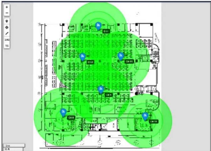
The illustration below depicts how a TX power value (TX=100%) in small area affects interference and background noise.
Figure 28 ZyXEL Wireless Optimizer 1.0 > TX Out Power of 100%
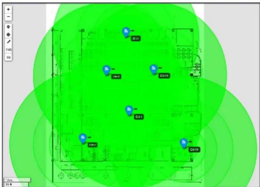
The illustration below depicts the usage of a proper value of TX power (TX=50%) in outer side and 25% TX power value for channel 1 in the office, which is a high density area at the center. This illustration also changes the channel planning to optimize the interference effect.
Figure 29 ZyXEL Wireless Optimizer 1.0 > TX Out Power of 50%
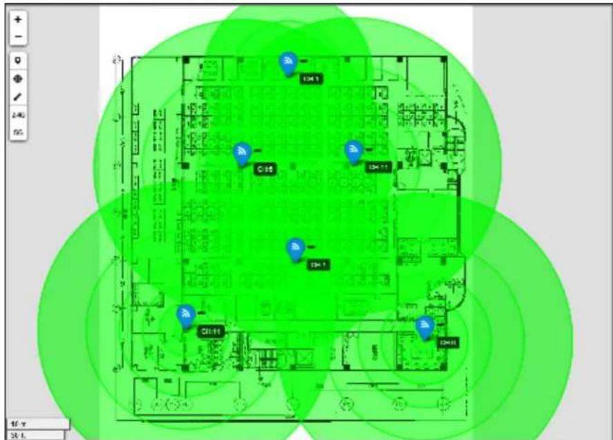
Reducing the TX power decreases the occurrence of co-channel interference in TX direction due to the existence of interference caused by the other AP or deployed AP with higher power.
In conclusion, you can see that reducing the 2.4GHz TX power to 50% or lower will work well for a high capacity area. It can also reduce co-channel/adjacent channel interference and background noise in the TX direction. However, the feasibility of this condition depends on the real environment factors. For example, if the interference is caused by other AP signal which is near the window or the street, then the most effective solution in such cases is to change the channel and then increase the output power when there are no free channels available.
For 5GHz, the TX power may not have to be reduced since the path loss in this case is more than 2.4GHz; as a result, there are more channels and hence, interference also is lesser than that in case 2.4GHz.
3.2.2 Channel Planning and Bandwidth Consideration
Channel Planning
A good channel planning is important factor to be considered during deployment for maximum utilization of air resource and reduction in interference. It should ensure that channels don't overlap and that the self deployed AP interference is avoided.
Although the DCS (Dynamic Channel Selection) option can be used to decide upon the channel in most cases, it is still vital to monitor the current channel planning since the real-time environment is ever-changing and may have unexpected interference.
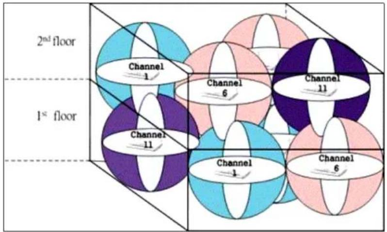
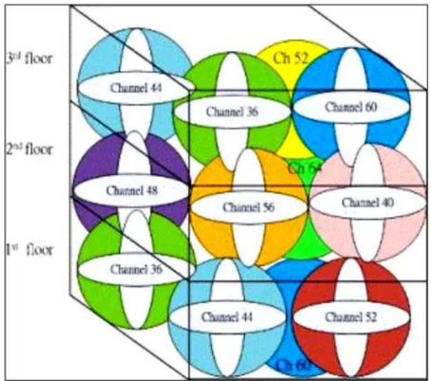
The channel number is displayed on the optimizer map and can be synced to the AC controller. In addition, the cross-floor channel planning also needs to be taken care of.
For further details, please refer to The Detail of WiFi Channels.
During the actual 2.4GHz deployment, there is a possibility of occurrence of channel overlap and hence, it is highly recommended that the system is maintained in a light loading area.
The figure illustrated below shows the channel planning reference.
Figure 30 Channel Planning Reference
Bandwidth
For 2.4G deployment, generally we use 20MHz with non-overlapping channels 1,6,11 in US or 1,5,9,13 in Europe.
For 5G deployments, it is advisable to use 20MHz, however, you can switch to 20MHz/Auto if there are free channels available.
3.2.3 Antenna Effect
Antenna plays an important role in wireless communication since it converts electric signals. It receives electronic signals into electromagnetic waves efficiently with minimum loss. Depending on the direction of radiation and other such factors, there are various types of antenna. One such type is an omni-directional antenna, which radiates electromagnetic waves uniformly in all directions.
The Gain and polarization (which refers to the orientation of electromagnetic waves) is the basic factor to the antenna. The external omni-directional antenna may not be the ideal choice for deployment, however, its overall performance is better than an internal invert-F PIFA antenna.
For modern devices such as the smart phone or the tablet, the polarization direction may change from vertical to horizontal when placed on a desk. Although the 45 degree placement of the omnidirectional antenna can adapt such situations in the horizontal direction, there will be considerable energy losses in the vertical direction. Hence, the 45 degree placement is an adaptive direction for each polarization but not the optimal direction. For information on the AP location in case of an internal antenna, please refer to Location.
3.2.4 Attenuation
A 2.4GHz deployment will demonstrate a lower path loss as compared to a 5GHz deployment under the same conditions.
The figure illustrated below shows the attenuation value of each material.
Figure 31 Attenuation Values
| 2.4 GHz Path loss | |
| Elevator | 35~40dB |
| Reinforced concrete | 20~40dB |
| Concrete Wall | 20~30dB |
| Concrete floor | 25~30dB |
| Red brick concrete wall (15-25cm) | 13~18dB |
| Metal doors | 6~8dB |
| Glass, Glass Window (3-5cm) | 6~8dB |
| Wooden wall (5-10cm) | 5~6dB |
| Hollow block brick wall | 4~6dB |
| Wooden door, Wooden furniture | 3~5dB |
| Simple plaster wall | 3~5dB |
3.2.5 Interference
To avoid interference from a deployed AP, do the following:
- Check its channel planning.
- Reduce the TX power level.
If the interference is from other device, do the following:
- Locate the bad area AP.
- Change the impacted AP to free available channel or increase the TX power.
- Monitor the total deployed channel planning to evaluate the co-channel interference effect after changing the TX power or channel on the impacted AP.
3.3 AP Deployment Considerations
3.3.1 Location
The radio coverage will depend on where the device is located. Ideally, it should be placed in:
• The centre of the service area
- A higher area to avoid barriers such as tops of tall furniture, shelves, cabinets, wall mounts, etc.
Do not install the device near:
- Other AP or radio transmitters
• Metallic devices such as radiators - A window
3.3.2 Coverage purpose
Having analyzed the various aspects of radio coverage, it can be summarized as follows:
- Maximize the AP TX power to attain maximum coverage.
Note: The overall capacity will decrease due to greater low rate area.
- Maintain a considerable distance between the deployed AP.
- Consider the client capability, since TX/RX capability is not the same.
- Interference and background noise caused by deployed AP is small.
- A weak signal/low rate area will be easily interfered by other strong signal AP.
- Channel planning is not so critical.
A coverage radius of 50m is possible in an open area with around 20 users and a good WiFi experience.
Note: For areas like home with concrete walls, keep only 1 wall penetration for ensure the clients with internal antenna can be connect.
3.3.3 Capacity purpose
Having analyzed the various aspects of radio capacity, it can be summarized as follows:
- Reduce the AP TX power to reduce interference and background noise between deployed APs.
• Channel planning is critical.
- Keep the clients in high rate area.
- Any modification on one AP will impact all the nearby deployed area.
- Increase the TX power if there are no other solutions (for example, change the channel) to the interference source.
- T h e ^nd AP radio (like 5GHz) will significantly increase the capacity when clients support.
For each radio, a coverage radius of around 20m in open office area is suggested with around 20\~30 users having good data service at the same time.
3.3.4 Roaming
The roaming decision is based on clients and its various settings such as the chipset driver setting. While the AP deployment can help suggest the clients about the roaming destination, it cannot influence the roaming decision of clients. In wireless communication, it is advisable to follow certain instructions, detailed below:
- Apply QoS/WMM on the specified application, for example, Skype Voice.
- Roaming condition is client dependent and for most clients, the roaming trigger point is -75dbm.
- Deployment consideration as capacity purpose if need voice or video continuity.
- Consider the limitation of clients, for example, the clients may have a weak wall penetration area and result in a bad roaming.
Troubleshooting
This chapter offers some suggestions to problems that you might encounter. The potential problems are divided into the following categories.
- AP Planning
• Correlating AP to AC
• Error Notifications Concerning AC - Setting Site Info and Preferences
4.1 AP Planning
How to perform AP planning?
Before the AP planning, gather all the possible information from the deployment site. This information will include business aspects such as customer demands and expectations, technical aspects such as the user quantity or user scenario, etc. Simply put, AP planning is balancing coverage and capacity by taking into consideration the real physical radio interference effect. With more information at hand, you can witness the results of a good planning right from the beginning.
To summarize, the ZyXEL Wireless Optimizer tool requires the following inputs:
- Image of the map or floor plan in the supported file formats such as .bmp, .gif, .jpg, .png
- Image of the map or floor plan with accurate real-time scale information.
• The desired AP model.
Procedure of AP Planning
- Import the image of the map or floor plan.
Figure 32 ZyXEL Wireless Optimizer 1.0 > Site Plan List
- Deploy one AP on the map.
Figure 33 ZyXEL Wireless Optimizer 1.0 > AP Planning Tool > Deploy AP
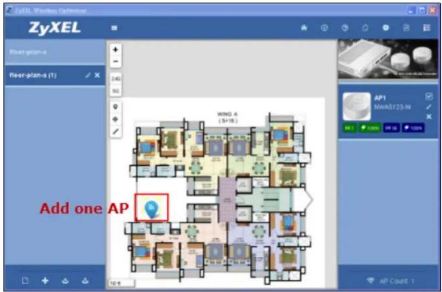
- Adjust the map scale to reflect the real-time scenario.
Figure 34 ZyXEL Wireless Optimizer 1.0 > AP Planning Tool > Unit Measuring
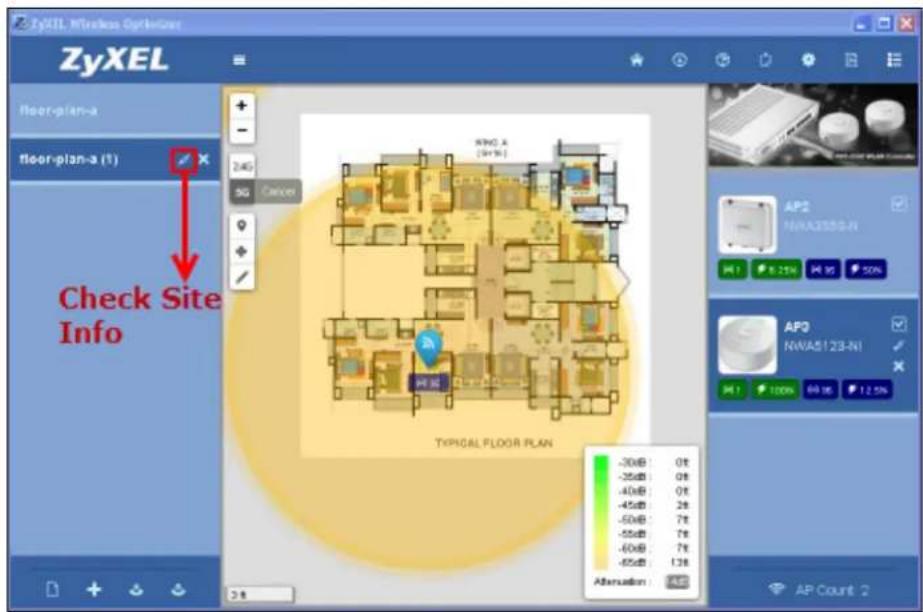
- Open the Site Information pop-up box.
- Adjust Regulation Region and Deployment Scenario such that they closely relate to your real-time scenario.
Figure 35 ZyXEL Wireless Optimizer 1.0 > Site Plan List > Site Info
- Deploy AP and move it to the desired location.
Figure 36 ZyXEL Wireless Optimizer 1.0 > AP Planning Tool > Relocate AP
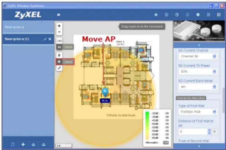
- Adjust the AP model. If required, you can fill the note or location string.
Note: Consider the real site situation, such as add a concrete wall to reduce the coverage. Take care of the high density area as such areas require more APs.
Figure 37 ZyXEL Wireless Optimizer 1.0 > AP List Window > AP Options
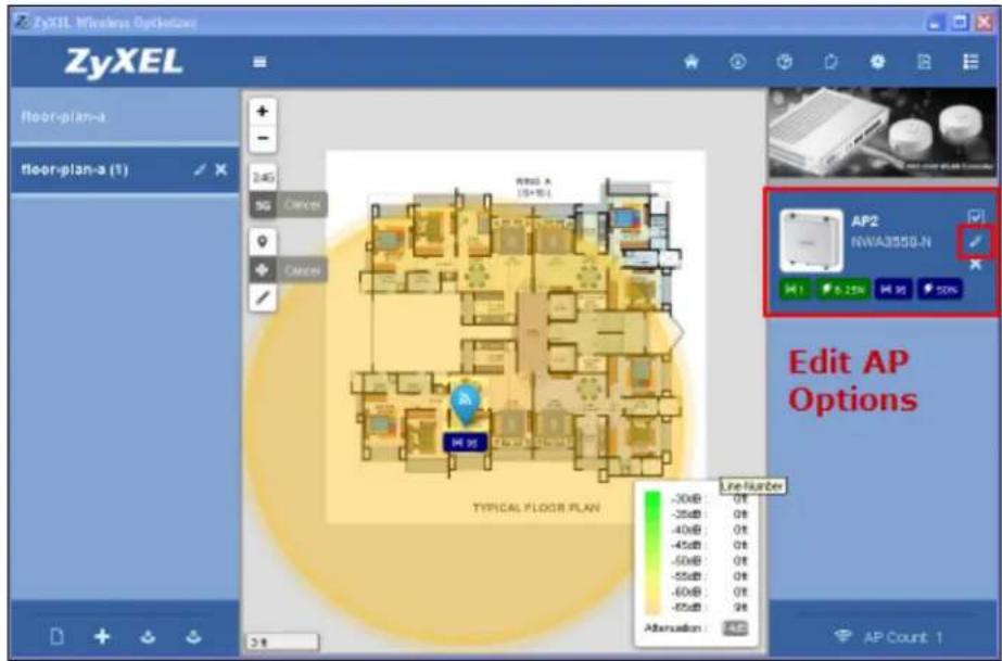
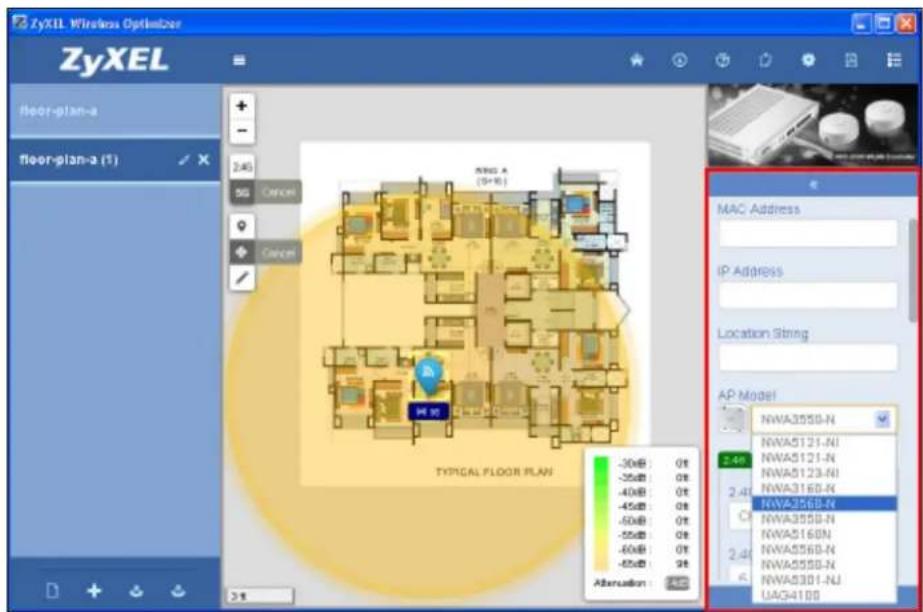
Figure 38 ZyXEL Wireless Optimizer 1.0 > AP Planning Tool > Deploy AP
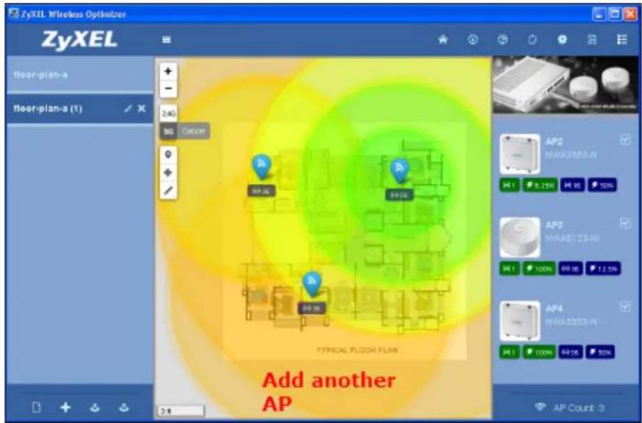
To achieve great results, please do the following:
- Perform channel planning to predict possible co-channel interferences. Channel planning is important to allocate all possible air resources.
- Reduce power to reduce the co-channel interference effect or check whether there is need for extra RSSI threshold settings for the deployed AP. To perform an advanced check, look for co-channel interference effects such as cross-floor.
- Check the total number of APs and verify whether they can provide the required capacity or throughput to the worst case users.
- Check details such as user demand and user scenario in different locations on the map. For example, the meeting room should consider more than the sidewalk; the planning should consider capacity demand in a high user density area and coverage in the area with less users.
- Discuss the results and explain them to the customer.
- Fine tune further details to meet the customer needs and expectations.
4.2 Correlating AP to AC
How to correlate AP to AC?
After deploying AP, the AP on MAP can correlate to the AC controller data and a geometric concept about the current AP status can be shown. In addition, the basic LAN and wireless status can be shown. This information can help user develop a clear picture on the current status of the deployed APs.
Note: Ensure that AP location is the deployed location and the map scale reflects accurate real-time scale information.
- Open the AC Connection Settings pop-up box.
Figure 39 ZyXEL Wireless Optimizer 1.0 > AP Planning Tool > Deploy AP
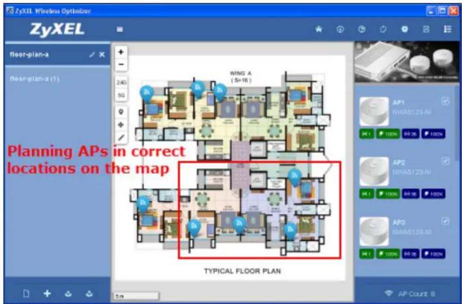
- Input the correct IP, user name/password and port setting.
Figure 40 ZyXEL Wireless Optimizer 1.0 > AC Options > Connection Settings
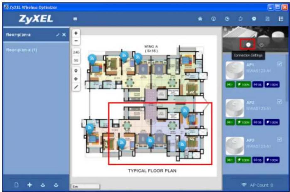
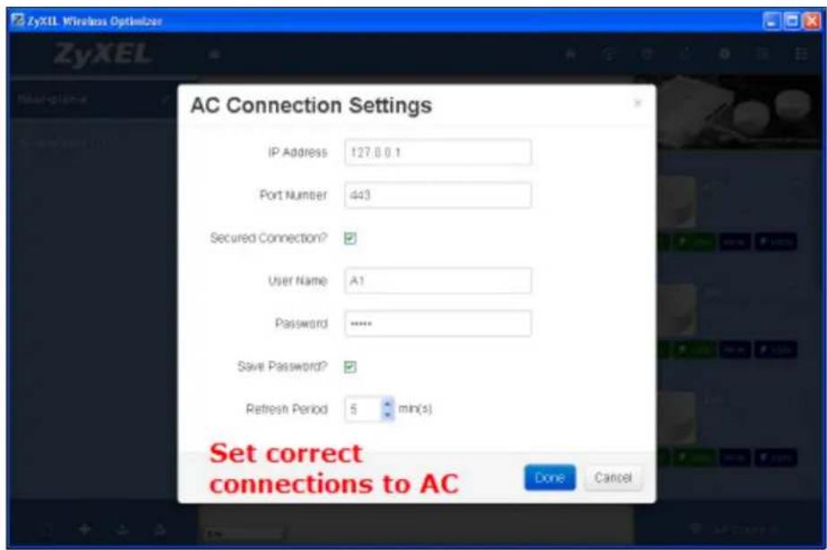
Note: The Refresh Period refers to the time by which the system will update the data from AC side periodically.
3. Press Connect to connect to AC. On a successful association, the system will display a successful connection message as a pop-up.
Figure 41 ZyXEL Wireless Optimizer 1.0 > Successful Association
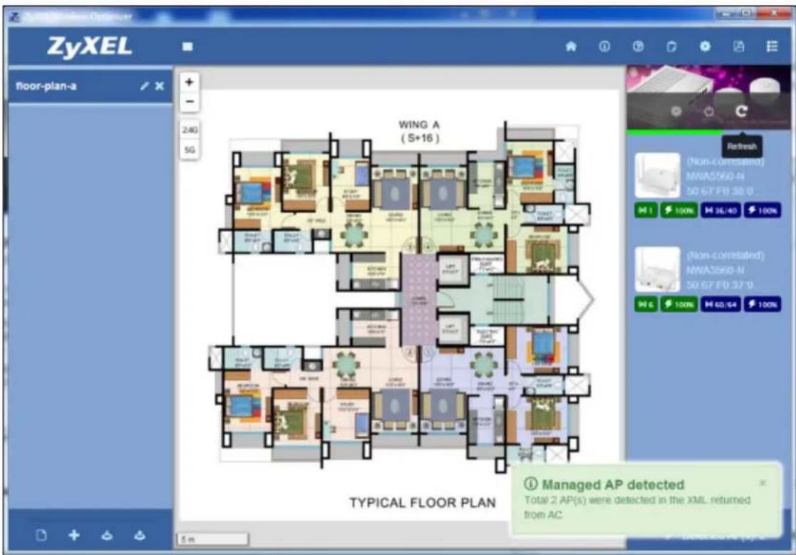
- Press Disconnect.
Figure 42 ZyXEL Wireless Optimizer 1.0 > AC Options > Disconnect
- In AP Option, select a MAC address for this AP.
Figure 43 ZyXEL Wireless Optimizer 1.0 > AP List Window > AP Options > MAC Address
- Press Connect. The AP will now correlate to the AC data and this AP will be shown on the map.
Figure 44 ZyXEL Wireless Optimizer 1.0 > Workspace > AP > Statistics of a Successfully Associated AP
- Repeat steps 4 and 5 to correlate the remaining APs. Now the AP on the map will show all the information from AC and periodically update the information displayed.
4.3 Error Notifications Concerning AC
I got an "Invalid XML" message from AC.
The AC site probably requires some time to prepare the data after reboot. Please wait a moment and try again.
I got a "Timeout" message from AC.
Please check whether your connection to AC is proper. This can be done by logging in through the web or using the ping command.
I got a "Connect to AC failed" message from AC.
Please check whether your user name, password and port settings are correct.
4.4 Setting Site Info and Preferences
How to display low signal coverage?
In the Preferences pop-up box, please adjust the Display Threshold field value.
What is the difference between the Country Regulation field in Preferences and Site Info?
In Preferences, the Country Regulation field setting is the default setting for a new map. Hence, this setting will only impact the newly inserted map.
In Site Information, the Country Regulation field setting is for the current map. Hence, this setting will apply only to the current map.
Legal Information
Notice to Users
Thank you for using "ZyXEL Wireless Optimizer!" By downloading, installing or using "ZyXEL Wireless Optimizer" software or any portion thereof ("ZyXEL Wireless Optimizer") you already agree to the following terms and conditions (the "DISCLAIMER OF WARRANTIES AND RESERVATION OF RIGHTS"). The ZyXEL Wireless Optimizer Software, and any portion there of, are referred to herein as the "Software."
Disclaimer of Warranties
The Software is currently made available to you free of charge.
THE SOFTWARE IS PROVIDED "AS IS", WITHOUT WARRANTY OF ANY KIND, EXPRESS OR IMPLIED, INCLUDING BUT NOT LIMITED TO THE WARRANTIES OF MERCHANTABILITY, FITNESS FOR A PARTICULAR PURPOSE AND NONINFRINGEMENT. IN NO EVENT SHALL THE AUTHORS OR COPYRIGHT HOLDERS BE LIABLE FOR ANY CLAIM, DAMAGES OR OTHER LIABILITY, WHETHER IN AN ACTION OF CONTRACT, TORT OR OTHERWISE, ARISING FROM, OUT OF OR IN CONNECTION WITH THE SOFTWARE OR THE USE OR OTHER DEALINGS IN THE SOFTWARE.
ZyXEL further reserves the right to make changes without notice.
Reservation of Rights
All rights are reserved by ZyXEL Communications Corporation.
You may not reverse engineer, decompile, disassemble, or otherwise attempt to discover the source code of the Software, except to the extent you may be expressly permitted under applicable law to decompile only in order to achieve interoperability with the Software. You will not make the Software available for use on other server, service bureau, or similar basis, on the Internet or otherwise.
Index
Numbers
2.4GHz 14, 15, 17, 23, 35, 36
5GHz 14, 15, 17, 23, 35, 36
A
AC Connection Settings 18, 20
AC Options 18
Access Points 14
Antenna Placement 37
AP
associating with AC 23
deployment 33
planning 23
planning and deployment 29
AP List Window 15
AP Options 17
AP Planning 8
AP Planning Tool 14
C
Capacity 32
Channel Planning 35
Client Output 17
Country Regulation 14, 23, 54
Coverage 32
Coverage Detection 8
Cross-floor 47
CSMA/CA 29
D
DCS 35
Display Threshold 23, 54
H
Hide 15
Hub 29, 30
|
IEEE 802.11 29, 31
Imperial 15
Installation 9
Interference 29, 30, 33, 35, 38, 39, 41
adjacent channel 33
co-channel 32, 35, 38, 47
L
Link Speed 31
M
Metric 15
MIMO 30
Multicast Transmission 33
N
Notifications 23
0
Options and Help 21
P
Port Number 20
Preferences 23
Wireless Health Management 8
Wireless Topology 30
WMM 29
R
Refresh 24
Refresh Period 20, 49
RSSI Threshold 47
Z
ZyXEL Wireless Optimizer
adjustment 7
after-sales maintenance 8
features 8
file format 13
image formats 9, 41
installation 9
NXC2500 WLAN controller 7, 8
overview 7
s
Site Information 14
Site Map 12
Site Plan List 12
site information 13
Successful Connection 19, 26, 53
System Requirement 9
T
Toggle AP 23
TX Out Power
100% 34
25% 34
50% 35
U
User Interface 11, 12
W
WiFi
overview 29
speed 31
WiFi Access Point Topology 30
WiFi Channels 29
- ZyXEL Wireless Optimizer
- IMPORTANT!
- KEEP THIS GUIDE FOR FUTURE REFERENCE.
- Table of Contents
- Part I: User's Guide .... 5
- Chapter 1 Understanding the ZyXEL Wireless Optimizer....7
- Chapter 2 Tutorials....11
- Part II: Technical Reference....27
- Chapter 3 AP Planning & Deployment Guide ....29
- WiFi Overview 29
- Concept of AP Deployment .... 33
- AP Deployment Considerations .... 38
- Chapter 4 Troubleshooting....41
- Appendix A Legal Information....56
- Index 58
- PART I
- User's Guide
- Understanding the ZyXEL Wireless Optimizer
- Overview
- Project Proposal and Planning Stage
- Adjustment after Deployment
- After-sales Maintenance
- Features
- AP Planning
- Coverage Detection
- Wireless Health Management
- System Requirement
- Operating System
- Processor
- RAM
- Disk Space
- Map Image Format
- Software Installation
- Tutorials
- Working with the ZyXEL Wireless Optimizer User Interface
- OR
- Working with the Site Map
- Site Plan List
- Site Information
- Working with the Access Points
- AP Planning Tool
- AP List Window
- AP Options
- Connecting to the AC
- AC Options
- AC Connection Settings
- Using Options and Help
- Preferences
- Planning AP and Associating AP with the AC
- Procedure
- Successful Association
- PART II
- Technical Reference
- AP Planning & Deployment Guide
- WiFi Overview
- WiFi Speed
- WiFi Speed v/s. Coverage and Capacity
- Multicast Transmission Conditions
- Concept of AP Deployment
- TX Power
- Channel Planning and Bandwidth Consideration
- Channel Planning
- Bandwidth
- Antenna Effect
- Attenuation
- Interference
- AP Deployment Considerations
- Location
- Coverage purpose
- Capacity purpose
- Roaming
- Troubleshooting
- AP Planning
- How to perform AP planning?
- Procedure of AP Planning
- Correlating AP to AC
- How to correlate AP to AC?
- Error Notifications Concerning AC
- I got an "Invalid XML" message from AC.
- I got a "Timeout" message from AC.
- Setting Site Info and Preferences
- Legal Information
- Notice to Users
- Disclaimer of Warranties
- Reservation of Rights
- Index
- Numbers
- A
- C
- D
- H
- |
- L
- M
- N
- 0
- P
- R
- Z
- s
- T
- U
- W
Brand : ZYXEL
Model : Wireless Optimizer
Category : Network card / adapter