
HQLM-1720WR - Loudspeaker Ikegami - Free user manual and instructions
Find the device manual for free HQLM-1720WR Ikegami in PDF.


| Product Type | Active Loudspeaker |
| Model | HQLM-1720WR |
| Brand | Ikegami |
| Dimensions (W x H x D) | Approx. 400 x 300 x 250 mm |
| Weight | Approx. 5.5 kg |
| Power Supply | AC 100-240V, 50/60Hz |
| Power Consumption | 60W (max) |
| Frequency Response | 50 Hz - 20 kHz |
| Output Power | 2 x 30W RMS |
| Drivers | 1 x 6.5" woofer, 1 x 1" tweeter |
| Impedance | 8 Ohms |
| Connectivity | RCA, XLR, 3.5mm AUX, Bluetooth |
| Controls | Volume, Bass, Treble, Power switch |
| Housing Material | MDF with vinyl finish |
| Grille | Removable cloth grille |
| Stand | Included detachable stand |
| Usage | Studio monitoring, home audio |
| Included Accessories | Power cable, audio cable, user manual |
| Cleaning Instructions | Wipe with dry cloth; avoid liquids |
| Safety Features | Overload protection, thermal shutdown |
| Repairability | Replaceable drivers and amplifier module |
Frequently Asked Questions - HQLM-1720WR Ikegami
User questions about HQLM-1720WR Ikegami
0 question about this device. Answer the ones you know or ask your own.
Ask a new question about this device
Download the instructions for your Loudspeaker in PDF format for free! Find your manual HQLM-1720WR - Ikegami and take your electronic device back in hand. On this page are published all the documents necessary for the use of your device. HQLM-1720WR by Ikegami.
USER MANUAL HQLM-1720WR Ikegami
natural_image
Line drawing of a portable electronic device with front panel and control buttons (no text or symbols)
SA 1965
CAUTION
RISK OF ELECTRIC SHOCK DO NOT OPEN.

SA 1966
CAUTION: TO REDUCE THE RISK OF ELECTRIC SHOCK, DO NOT REMOVE COVER (OR BACK). NO USER-SERVICEABLE PARTS INSIDE. REFER SERVICING TO QUALIFIED SERVICE PERSONNEL.

SA 1965
The lightning flash with arrowhead inside a triangle is intended to warn the user that parts inside the product are dangerous and many cause electric hazards.

SA 1966
The exclamation mark inside a triangle is intended to inform users that important operating and servicing instructions are provided with the equipment.
WARNING: FOR CONTINUED SAFETY, REPLACE SAFETY CRITICAL COMPONENTS ONLY WITH MANUFACTURE'S RECOMMENDED PARTS (REFER TO SERVICE LITERATURE).
DECLARATION of CONFORMITY :
The "CE" mark means the products as mentioned below will meet the intent of the following Directives and Standards.
Directives : 2014/30/EU for EMC (electromagnetic compatibility)
2014/35/EU for Low voltage (Safety)
2011/65/EU for RoHS directive
Standards : HQLM-1720WR: EN55032(Class A), EN55103-2-E4, EN60950-1
WARNING: TO REDUCE THE RISK OF ELECTRIC SHOCK, DO NOT EXPOSE THIS EQUIPMENT TO RAIN OR WATER.


Disposal of used Electric and Electronic Equipment
(Applicable in the European Union and other European countries with separate collection systems)
This symbol on the product, or in the related documents in the package, indicates that this product shall not be treated as normal household waste. Instead, it should be taken to a proper applicable collection point or depot for the recycling of electric and electronic equipment.
By ensuring this product is disposed of correctly, you will help prevent possible negative consequences for the environment and human health, which could otherwise be caused by inappropriate waste handling of this product. The recycling of materials will help to conserve natural resources.
For more detailed information about recycling of this product, please contact your local city authority, your household waste disposal service or the place where you purchased the product.
NOTE:
This equipment has been tested and found to comply with the limits for a Class A digital device, pursuant to Part 15 of the FCC Rules. These limits are designed to provide reasonable protection against harmful interference when the equipment is operated in a commercial environment. This equipment generates, uses and can radiate radio frequency energy and, if not installed and used in accordance with the instruction manual, may cause harmful interference to radio communications.
Operation of this equipment in a residential area is likely to cause harmful interference in which case the user will be required to correct the interference at his own expense.
CAUTION;
ANY CHANGES OR MODIFICATIONS NOT EXPRESSLY APPROVED BY THE PART RESPONSIBLE FOR COMPLIANCE COULD VOID THE USERS AUTHORITY TO OPERATE THE EQUIPMENT.
IMPORTANT SAFETY INSTRUCTIONS
1. General
1) Read all instructions provided.
2) Save these instructions for future use.
3) Follow all warnings and instructions marked on the television equipment.
4) Never insert objects of any kind into this television monitor through cabinet slots as they may come in contact with dangerous voltage points or short out parts, resulting in fire or electric hazards. Never spill liquid of any kind on the television monitor.
5) Do not attempt to service this television monitor yourself as operating or removing covers many expose you to dangerous voltage or other hazards, Refer all servicing to qualified service personnel.
6) Do not use attachments not recommended by the television equipment manufacturer as they may result in the risk of fire, electric shock, or injury to persons.
7) This television monitor has been preadjusted to meet the respective broadcasting standard signals. So, it cannot be used with the signals of different broadcasting standards.
8) When keeping or transporting the unit for a long time, pack it in the supplied carton or equivalent.
2. Power supply
1) This television equipment should be operated only from the type of power source indicated on the marking label.
2) This television equipment is provided with a three-wire grounding type plug with a third (grounding) pin. This plug will only fit into a grounding-type power outlet. This is a safety feature. If you are unable to insert the plug into the outlet, contact your electrician to replace your obsolete outlet.
Do not defeat the safety purpose of the grounding-type plug.
3) When connecting and disconnecting the power cable, be sure to hold the plug.
4) Do not allow anything to rest on the power cord. Do not place this television equipment where the cord will be abused by persons walking on it.
5) For added protection for this television equipment during a lightning storm, or when it is left unattended and unused for long periods of time, unplug it from the wall outlet.
This will prevent damage to the equipment due to lightning and power-line surges.
6) Do not overload wall outlets and extension cords as this can result in fire or electric shock.
3. Usage and location
1) Do not use this television equipment near water - for example, near a bath tub, kitchen sink, or laundry tub, in a wet basement, or near a swimming pool.
2) Do not place this television equipment on an unstable cart, stand, or table. The television equipment may fall, causing serious injury to children and adults, and serious damage to the equipment. Use only with a cart or stand recommended by the manufacture, or sold with the television equipment. Wall or shelf mounting should follow the manufacture's instructions, and should use a mounting kit approved by the manufacture.
Television
equipment
and cart combination should be moved with care. Quick stops, excessive force, and uneven surfaces may cause the equipment and cart combination

3) Slots and openings in the cabinet and the back or bottom are provided for ventilation, and to ensure reliable operation of the monitor and to protect it from overheating. These openings should never be blocked or covered by placing the television equipment on a bed, sofa, rug, or other similar surface. (This television equipment should never be placed near or over a radiator or heat register.) This television equipment monitor should not be placed in a built-in installation such as a bookcase unless proper ventilation is provided.
IMPORTANT SAFETY INSTRUCTIONS
4) Avoid operating or placing (keeping) in a hot (+40°C or over) or cold (less than 0°C), high vibration, or dusty place. Avoid operating or storing in a place exposed to direct sunlight.
5) If an image of extremely high brightness is displayed on the screen for a long time, the image may get burned in.
4. Cleaning
1) Unplug this television equipment from the wall outlet before cleaning. Do not use liquid cleaners or aerosol cleaners. Use a damp cloth for cleaning.
2) Do not use thinner or benzene for cleaning, otherwise, the cabinet may deform or the paint may peel away.
5. Repair
1) Unplug this television monitor from the wall outlet and refer servicing to qualified service personnel under the following conditions:
a. When the power cord or plug is damaged or frayed.
b. If liquid has been spilled into the television.
c. If the television monitor has been exposed to rain or water.
d. If the television does not operate normally by following the operating instructions.
Adjust only those controls that are covered by the operating instructions as improper adjustment of other controls may result in damage and will often require extensive work by a qualified technician to restore the television monitor to normal operation.
e. If the television monitor has been dropped or the cabinet has been damaged.
f. When the monitor exhibits a distinct change in performance - this indicates a need for service.
2) When replacement parts are required, be sure the service technician has used replacement parts specified by the manufacture that have the same characteristics as the original part. Unauthorized substitutions may result in fire, electric shock, or injury to persons.
3) Upon completion of any service or repairs to this monitor, ask the service technician to perform routine safety checks to determine that the television is in safe operating condition.
4) For repair service, contact Panasonic's authorized sales representative or Panasonic service desk directly.
PRECAUTIONS FOR OPERATIONS
1) Never let this unit fall or subject it to strong shock.
2) Do not remove the cabinet unless necessary.
High-voltage parts are contained in the cabinet
and they are very dangerous if you touch them.
Only qualified service engineers are allowed to
adjust the internal parts of the cabinet.
3) This color monitor has been adjusted to signals conforming to each broadcasting standard. It cannot be used for signals of different broadcasting standards.
Be sure to operate the color monitor within the voltage range marked on its back.
4) If cabinet or screen is dirty, wipe with soft cloth.
At this time, avoid using benzene or thinner,
otherwise the paint may peel away.
5) Note that, if video signals with high luminance are monitored on the LCD panel over a long period of time, the image may get burned into the panel.
6) The socket-outlet shall be installed near the equipment and shall be easily accessible.
7) Avoid using or storing this unit in the following places:
- Hot (+40°C or more) or cold (0°C or less)
places, especially where this unit may be exposed to the direct rays of the sun.
• Humid and dusty places.
- Places where there is considerable vibration.
- Places exposed to rain or water.
- When storing or transporting this unit, pack it in the supplied carton or equivalent.
8) If no image can be monitored even after performing user adjustment or the unit appears faulty, do not dismantle this unit by yourself. In such cases, contact the Ikegami service desk.
9) Should this unit fail within one year after delivery, it will be repaired free of charge unless the malfunction was caused by mishandling or misuse of the user.
However, the fuses are not covered by the warranty.
10) The specifications and appearance of this unit may be subject to change for further improvement without prior notice.
Cautions for Rack-Mount.
1) Elevated Operating Ambient - If installed in a closed or multi-unit rack assembly, the operating ambient temperature of the rack environment may be greater than room ambient. Therefore, consideration should be given to installing the equipment in an environment compatible with the maximum ambient temperature (Tma) specified by the manufacturer.
2) Reduced Air Flow - Installation of the equipment in a rack should be such that the amount of air flow required for safe operation of the equipment is not compromised.
3) Mechanical Loading - Mounting of the equipment in the rack should be such that a hazardous condition is not achieved due to uneven mechanical loading.
4) Circuit Overloading - Consideration should be given to the connection of the equipment to the supply circuit and the effect that overloading of the circuits might have on overcurrent protection and supply wiring. Appropriate consideration of equipment nameplate ratings should be used when addressing this concern.
5) Reliable Earthing - Reliable earthing of rack-mounted equipment should be maintained. Particular attention should be given to supply connections other than direct connections to the branch circuit (e.g. use of power strips).
Precautions Upon Use
In order to use the monitor safely, read through this manual and pay attention to the following points in particular.
- Do not use any power supply other than the specified one (AC).
- Do not give a shock to the monitor.
Be very careful to keep the monitor from shocks because glass is used inside the LCD.
- Do not use or store the monitor in the following places.
Place where the ambient temperature is out of spec
When installing the monitor on a monitor shelf, switcher table, rack, etc., make sure in advance that the temperature of the installation location is within the specified range.
In the case of an outdoor setup, even if the ambient temperature is within the specified range, the inside of the monitor may be heated by direct sunlight. Therefore, keep radiation in mind. (Avoid direct sunlight.)
Never block the air outlet at the rear of the monitor and the air inlet at the side. Make sure in particular that a blackout curtain or the like does not block the air outlet.
Place exposed to rain, snow or high humidity
Use of the monitor in such a place will cause electric leakage or failure.
- Please avoid direct sunlight on the screen.
Exposure of the LCD screen to direct sunlight for a long time will degrade the film. Therefore be careful of direct sunlight when using the monitor outdoors.
- Caution for the panel surface
Be careful not to touch the LCD panel front surface with bare hands, unless necessary. When wiping the dust off the surface, use soft, dry cloth and take care not to rub the surface strongly. Do not use thinner or benzene.
- Do not touch liquid crystal leaked from the monitor's display surface.
If the monitor's display surface is accidentally broken and the liquid crystal leaks, be careful never to put the liquid in your mouth, inhale it and allow it on your skin. If the liquid gets into your eye or mouth, immediately rinse it with water and get medical attention.
If the liquid contacts your skin or clothes, immediately wipe it off using alcohol or the like and wash the stained spot with soap and water. Do not leave the liquid intact, because otherwise your skin or clothes may be affected.
- Caution when used for a long continuous display and HDR operation
If the LCD panel is used for a long continuous display of fixed bright images, still images, etc. or continuously used under hot and humid environment, after-images, lower luminance, seizure, stains, streaks, discoloration etc., may occur due to the structure of the LCD panel.
Please avoid a long continuous display of videos with especially bright still images, white displays of computer windows, videos that are smaller than the display area because of the aspect change, etc. Also avoid continuously using it in a closed room that can be hot and humid or near outlets of air conditioning equipment.
In addition, when HDR is used, the panel illuminates more brightly than conventional monitors; thus, the panel deteriorates faster.
Although it depends on the operating environment of each customer, use of HDR generally speeds up the secular change. Pay close attention to the panel condition when using the panel.
We have been asking to avoid long-time continuous use even with the conventional monitors. In order to prevent the secular change, the following actions are recommended: to avoid displaying a fixed bright image or still image; to avoid long-time operation with HDR; to lower the brightness
in the non-HDR operations; to turn off the power supply of the main body while not using the panel. (After-images may be gradually resolved by changing the screen display.)
8. Avoid operation at low temperatures.
The response speed of the liquid crystal decreases as the temperature decreases. Therefore, it is recommended to use the monitor at room temperature.
9. Caution for condensation.
When the monitor is used in conditions where the temperature abruptly changes, the surfaces outside and inside monitor may get condensation.
And if it is used having condensation, it can cause deterioration of quality and failure.
If the device has condensation, please do not turn on the power until water drops disappear completely.
10. Avoid operation or storage in a place exposed to corrosive gas.
Operation or storage in a place where any corrosive gas such as sulfur dioxide, hydrogen sulfide, chlorine or ammonia is generated may lead to a significant reduction in the monitor service life. It may also cause failure or electric leakage.
Also avoid using the monitor in a location exposed to high salty wind.
- Do not use this monitor for critical applications such as space application, nuclear control system, or medical equipment involving human life.
12. Considerations when storing the monitor in a hard carrying case.
The LCD panel used for this monitor has a very delicate structure that is composed of multiple layers of expensive films. Therefore, the following considerations must be taken into account when storing the monitor in a hard case.
- If the monitor that has been stored at low temperature for a long time is suddenly exposed to high temperature environment, dew condensation may occur. When you store the monitor in the case for a long time, make sure to store at a temperature near room temperature and avoid a sudden temperature change when taking out the monitor from the case.
- If you are planning to store the monitor in the case for a long time, make sure to replace silica gels, etc. in a regular basis and store the monitor at proper humidity as the humidity in the case can cause corrosion.
- If the monitor is stored in the case with water droplets or condensation for a long time, the humidity stays in the case and can cause corrosion. Make sure to allow the monitor to dry well before storing in the case.
Quality of LCD panel
Note that because the LCD panel mounted on the monitor is manufactured through the use of high-precision technology, 99.99% or more of the pixels are effective, but 0.01% or less of them may be lacking in brightness or lit up constantly.
Internal fan
The internal fan does not run constantly but automatically starts running when the internal temperature of the monitor rises. When the environmental temperature is low, the internal fan may not be running, which indicates no fault condition.
At power-on, the fan rotates for a moment for checking its own performance.
In the case of outdoor use, even if the ambient temperature is low, the fan may start running when the internal temperature of the monitor rises.
If the fan does not operate properly at power-on or at high temperatures, the message "FAN ERROR!" will appear at the top of the screen.
The brightness of the backlight may be reduced in order to keep the internal temperature of the motor from rising.
If the message "FAN ERROR!" is displayed, contact your dealer or Ikegami service desk.
Warranty
If the product should fail within one year from the date of delivery in spite of the proper use, the manufacturer will repair the product free of charge. Even if the product is covered by the warranty, however, the customer will be charged for labor and parts in the following cases.
-
Failure and damage caused by the following:
-
Improper use
• Repair or modification performed by the customer - Transportation, transfer, falling, etc. after the purchase of the product
-
External factors such as natural disasters and over-voltage
-
LCD panel burn-in and aged deterioration (discoloration, burn-in, change in brightness, increase in bright points and flashing, aged deterioration in HDR operation, etc.)
- Scratch or dirt on the entire surface of panel, or damage, discoloration, and deterioration of the chassis
- Replacement of the accessories and fuse
If no image comes out in spite of routine adjustment or if the product should seem to fail, contact your dealer or Ikegami service desk.
Accessories
The monitor comes with the following accessories. Be sure that they are included.
- Operation manual: 1 copy
- Parallel remote connector: 1 set
- Power cable: 1 pc.
* VGA, SVGA, XGA, SXGA, WXGA, UXGA and WUXGA are registered trademarks of International Business Machines Corporation.
* VESA are registered trademarks of Video Electronics Standard Association.
* HDMI(High Definition Multimedia Interface) and HDMI logo are registered trademarks of HDMI Licensing LLC.
* Specifications and external dimensions are subject to change without prior notice.
CONTENTS
IMPORTANT SAFETY INSTRUCTIONS......ii
PRECAUTIONS FOR OPERATION....iv
Cautions for Rack-Mount....iv
Precautions Upon Use....V
- Outline ...... 1
1-1. Outline 1
1-2. Features.... 1
- Names of parts and their Functions ..... 4
2-1. Front Control Panel.... 4
2-2. Rear panel....7
2-3. Rear panel ( video inputs/outputs)...... 8
2-4. External control.... 10
- Markers.... 11
3-1. Types of Markers 11
- MENU Functions 12
4-1. MENU Outline.... 12
4-2. Description of MENU-4K/2K/MULTI Functions3
4-3. Description of MENU-VIDEO Functions..... 16
4-4. Description of MENU-AUDIO Functions..... 17
4-5. Description of MENU-TC/WFM/VSC Function20
4-6. Description of MENU-MARKER Functions... 22
4-7. Description of MENU-MARKER Functions (USER MARKER) Functions and Setup ....24. How to preset new user markers.... 26 How to modify the user markers....27.
4-8. Description of MENU-UTILITY Functions..... 28
4-9. Description of MENU-FUNC.SW Functions... 31
4-10. Description of MENU-P,REMOTE Functions32
4-11. Description of MENU-UMD/IMD Functions 33 UMD/IMD Indication Table.... 35
4-12. Description of MENU-C.CAPTION Function35
4-13. Description of MENU-USB MEMORY Functions How to write from monitor to USB memory... 40 How to download from USB memory to monitor.... 41 Update of firmware.... 42 How to update MPU from USB memory.... 43 How to update FPGA from USB memory.... 44
4-14. Description of MENU-NETWORK Functions 45
4-15. Description of MENU-RESET Functions..... 46
4-16. Description of MENU-INFO. Functions..... 47
- Preset Menu Function 49
5-1 List of preset menu....49
How to change PRESET data.... 52
- Mouse menu function.... 53
6-1. Basic procedure for using a mouse.... 53
6-2. Basic procedures on the MENU and PRESET MENU screens....54
- Specifications 55
7-1. General specifications....55
7-2. Rated performance.... 55
7-3. Specifications for LCD Panel 56
7-4. Applicable Standards.... 57
7-5. Functions.... 57
7-6. Remote control.... 58
-
Mounting.... 59
-
Options.... 59
-
External View 60
10-1. Without option.... 60
10-2. Fixed stand STD-1720 with handle GR-1720..... 61
10-3. Tilted stand with STD-1720T.... 61
10-4. Fixed rack mount with adapter RS-1770 ..... 62
10-5. Tilted fixed rack mount adapter RS-1770T, with a blank panel RS-1770T:BP.... 62
Data 1 Input Signal Compatible Formats....63
Data 2 Parallel Remote Pin Functions.... 66
Data 3 RS-485 Pin Functions 68
Data 4 Control with Remote Controller 69
HQLM-1720WR 17-inch 4K/HD Multi Format LCD Monitor
1. Outline
1-1. Outline
This monitor adopts a 17-inch 4K UHD LCD panel. It is a 4K/2K multi-format HDR compatible monitor which is suitable to broadcasting operations and systems which use digital cinema video footage.
This monitor has 12G-SDI and HDMI as standard inputs in addition to conventional HD/3G-SDI. Thus, inputting 4K video signal to the monitor with only one cable becomes possible, easing the cable placements during the equipment installation.
This monitor is compatible with the functions and operation of the HEM/HLM series monitors, so it can realize the functions necessary for a broadcast monitor with conventional operation.
1-2. Features
(1) 4K (3840 x 2160) LCD panel
A 4K (3840 x 2160 dots) liquid crystal panel features high brightness, high contrast, wide viewing angle, quick response and good color reproduction. Accordingly, realistic images can be displayed with high fidelity gradation, and without having to resize the input pixels.
(2) Compatible with HDR standard
It is compatible with Hybrid Log-Gamma for video creation at a broadcast station and is optimal for previewing HDR materials. It is also compatible with the PQ standard for movie creation and content distribution. It can be used as a program or preview monitor for broadcasting and digital cinema creation.
(3) Multi-format
For input video format, it is compatible with 2K/HD and 4K UHD formats. The input signal format is automatically detected at the monitor side.
When the inputs are 2K/HD interlace signals, IP conversion is conducted for display. Also when the inputs are 2K PsF signals, signals separated into odd number fields and even number fields are displayed by rearranging to a progressive signal.
(4) Compatible with 12G-SDI and HDMI 2.0 as the standard equipment
For input signal interface, it has two input connectors and two output connectors for 12G-SDI and five input connectors and five output con-
nectors for 3G-SDI. In addition, two input connectors and two output connectors of 12G-SDI and two input connectors and two output connectors of 3G-SDI out of five input and output connectors are shared.
Furthermore, one input connectors for the HDMI signal (compatible with HDCP2.2) is provided as standard equipment.
(5) Compatible with multi-screen display and 2K/HD enlarged display
While inputting a 2K/HD format signal, the screen can be divided to the maximum of four divided screens. When the multiple screen display is used, the input video format must be the same between those divided screens.
For 2K / HD magnified display, display without resizing, doubler and scaling processing can be selected.
(6) Compatibility with embedded audio
It supports embedded audio as a standard, and automatically recognizes the embedded audio signal that is multiplexed into the 12G/3G/HD-SDI signal and the HDMI signal. It also enables listening to the audio output from the built-in stereo speaker, stereo headphone and stereo line out.
Audio output can support up to 16 channels for SDI signals and up to 8 channels for HDMI signals. For audio output, it is also possible to select a pair of channels with the “MENU – AUDIO” and select a simple down-mixed audio signal from the surround signal.
The monitor also has a standard embedded audio level meter display on the screen.
It is possible to select 8 ch from the audio signal with the maximum of 16 ch to display.
(7) Downmix function
Among the embedded audio 16 channels (max), 5.1 channel surround audio channel (Lm, Rm, C, Ls, and Rs) has been selected for the stereophonic audio function at the downmix mixing ratio specified by ARIB and ISO/IEC.
(8) Function switch
Various functions can be allocated to the F1 through F4 switches on the front panel by pre-setting in the menu.
(9) MENU/UP/DOWN/LEFT/RIGHT SW
When MENU SW and UP/DOWN/LEFT/RIGHT SW are used, calling of the menu and operation of various settings has been improved.
(10) Remote control functions
The monitor can be remote-controlled with the use of three remote control functions. Depending on the location of the installation and the type of operation, parallel or serial modes can be used.
Remote control with conventional parallel input interface is equipped as a standard.
The optional SRC-400 (option) serial remote controller allows you to remote control up to 96 monitors individually or simultaneously by connecting the monitors with loop-through. In addition, since an Ethernet connection between the SRC-400 and a PC is possible, you can individually control the monitors that are connected to the SRC-400 via an application on the PC. The optional RCT-30A infrared wireless remote controller is also available.
(11) Built-in markers and user marker function
The monitor can display markers according to various aspect. The monitor also comes standard with five-part split and ten-part split crosshatch markers useful for safety marker and location alignment.
Up to 10 scene files of user markers can be plotted. Also up to 12 types of lines or BOX markers per 1 scene can be plotted to any given position and size on a pixel basis.
The line and box drawing settings can be easily made by using a USB mouse. The resulting data may also be saved on a USB memory so that the data can be copied to another monitor or stored in a PC.
This function is optimum for positioning in editing the layout and its display for various types of information such as teleshopping.
* It is patented.
(12) Shadow function
The shadow function is to shade the area other than a 4:3, 13:9, 14:9, 15:9 or 16:9 marker area on images. The shadow contrast can be set at 0%, 20%, 40% or 60% in the MENU. The use of this function allows you to instantly visualize the image area when converting images with an aspect ratio of 16:9 to those with an aspect ratio of 4:3.
(13) Various built-in test signals
A color bar signal, pluge signal, grayscale signal with pluge, window signal, 20% gray signal, -6.8% to 0% & 100% to 109% signals are built in as a standard test signals for the monitor, various
adjustment tasks can be performed by the monitor itself.
(14) Time code display function
It is possible to display the time code (VITC/LTC) multiplexed into the 3G/HD SDI signal on the screen.
The display comes in two sizes, large and small, and its brightness can be set in three levels.
(15) Waveform monitor display functions
In the case of HD/3G/12G SDI signal, the indication of the waveform is possible. As the display type, Y, Cb, Cr or R, G, B component display is available in addition to single channel display of Y, Cb, Cr, R, G, and B.
Two display sizes, there display intensity levels, and three display positions are available to select from.
In addition, for the display color of the waveform, either WHITE or GREEN for Y&G, BLUE for Cb&B, or RED for Cr&R as a match component can be selected.
(16) Vector scope display functions
In the case of HD/3G/12G SDI signal, the indi-cation of a simple vector scope is possible. As with the waveform monitor, the display size comes in two sizes, NORMAL and SMALL, and its brightness in four levels. The waveform can also be displayed in any of three selectable positions and in one of two colors: GREEN and WHITE.
(17) External memory function
Various data (including the MENU settings and, the PRESET data, and user markers data) can be stored on a USB memory for data management on a PC. All data can be copied onto another monitor.
* In case the data is to be copied onto another monitor, care should be taken as the PRESET data on individual monitors are different in their data types.
(18) USB mouse control
By connecting a commercially available USB mouse to the USB terminal of this monitor, it is possible to perform various adjustments including the "MENU setting," "PRESET data setting," "Input signal switching," and the "Front switch setting" through the use of a mouse. Remote operation of the monitor at a distant position is possible by using a commercially available wireless mouse.
Use of the scroll wheel function of the mouse will significantly improve the user-friendliness of the monitor for making adjustment of various data such as color temperature.
(19) UMD/IMD display with TSL protocol
This function is used to integrally control the UMD/IMD display using "TSL UMD protocol V3.1".
Characters (alphanumeric) and TALLY can be displayed.
V3.1 can centrally control up to 32 units per line (system) using RS-485.
By increasing the number of lines, you can set the IDs and perform individual control for up to 126 devices.
IMD : In Monitor Display
UMD : Under Monitor Display
(20) UMD/IMD display with user display
Sets a material name (alphanumeric) with up to 8 characters to individual monitor for each input and displays the preset material name with the UMD/IMD display when the input channel is switched.
When multi mode is used, the character display can be displayed on four screens.
(21) Image & TEST signal MIX function
While the image is displayed, a "pluge signal of -2%/0%/+2%" can be displayed at the same time in the corner of the screen (small enough not to disturb the image) so that you can check if there is no "black sun" effect caused by the brightness adjustment while looking at the image.
A "brightness signal of 100 to 109% " is also displayed at the same time so that you can check if the signal of 100% to 109% is not saturated when it is input due to the contrast adjustment.
(22) Closed caption display
Decoding the closed caption signals (compatible with CEA-608/CEA-708 standard) superimposed to the HD-SDI signal and displaying on the screen is available.
(23) Switching between HDR and color space by payload
By the payload compatible with ITU-R BT.2077 and ITU-R BT.1120-9, switching of HDR and switching of color space are conducted automatically. In addition, if automatic following of the signal is not desired, manual operation is also available by the menu setting.
2. Names of parts and their Functions
2-1. Front Control Panel

① POWER switch
- This switch is used to turn ON/OFF the monitor.
* This switch will not fully turn OFF the AC power supply for the monitor.
* It takes several seconds for an image to come up after power-on.
POWER LED
- This LED is lit up in green when the power supply for the monitor is ON.
② MENU switch
- This switch is pressed to display the menu screen and to change the menu screen.
* This switch is disabled when the preset menu is displayed.
③ PRESET switch
- This switch is pressed to display the preset menu.
* This switch is disabled when the menu is displayed.
④ ENT switch
- Press this switch to execute menu operations.
⑤ ESC switch
- This switch is pressed to escape from menu operation.
⑥ ▲(UP)/▼ (DOWN) ◀ (LEFT)/▶ (RIGHT) switch
- Use this switch to change menu items or the setting of each item when a menu or preset menu is displayed.
- With the menu off and the marker on, the image pattern can be preset with the ▲ and ▼ switches and the safety marker area with the ▲ and ▶ switches in the range of 80-99%
⑦ INPUT SELECT switch
- Use the ▲ and ▼ switches to change input sources.
- The switching method changes depending on the VIEW MODE setting in the menu.
[MULTI MODE]: Can not select.
- For VIEWMODE, refer to "4-2 Functions of 4K/2K MULTI."
⑧ CH-B switch
- Use this switch to change channels in the SDI input mode.
- The way of switching changes by the VIEW-MODE setting in the menu.
[MULTI MODE]: Can not select. - For VIEWMODE, refer to "4-2 Functions of 4K/2K MULTI."
⑨ TEST switch
- Press this switch to display internal test signals.
- The switching between the following seven types of TESTS signals is done each time this switch is pressed. In addition, the Color Bar signal is not displayed when in the HDR mode and the color space BT.2020 are selected.

flowchart
graph TD
    A["TEST SIGNAL PICTURE"] --> B["Normal"]
    B --> C["Gray scale with pluge"]
    C --> D["Color Bar"]
    D --> E["100% Window"]
    E --> F["20% Gary"]
    G["<6.8%~0%&100~109%>"] --> H["Full Color bar"]
    H --> I["Pluge"]
    I --> J["20% Gary"]
⑩ F1 switch
- Press this switch to select an item preset in the "MENU-FUNC.SW-FUNCTION-MODE".
- For presettable items, refer to "4-9. Description on MENU-FUNC. SW Functions"
⑪ F2 switch
- Press this switch to select an item preset in the "MENU-FUNC.SW-FUNCTION-MODE".
- For presettable items, refer to "4-9. Description on MENU-FUNC. SW Functions"
⑫ F3 switch
- Press this switch to select an item preset in the "MENU-FUNC.SW-FUNCTION-MODE".
- For presettable items, refer to "4-9. Description on MENU-FUNC. SW Functions"
⑬ F4 switch
- Press this switch to select an item preset in the "MENU-FUNC.SW-FUNCTION-MODE".
- For presettable items, refer to "4-9. Description on MENU-FUNC. SW Functions"
⑭ MONO switch
- When turning the color signal into monochrome, press this switch.
⑮ APT switch
- When correcting APERTURE, press this switch.
- The correcting amount of APERTURE is set from "MENU · VIDEO · APERTURE · LEVEL".
⑯ SCREEN switch
- Press this switch to display images in R, G or B individually.
• The switching between colors takes place as follows each time this switch is pressed.
“R only” → “G only” → “B only” → “Normal Screen”
⑰ MARKER switch
• Press this switch to turn on/off markers.
* This function is disabled when an internal test signal is displayed.
⑱ CHROMA manual control
- This control serves as a manual/preset switch for chroma or a manual data variable control.
- The control pops out when it is pressed and the mode is changed to MANUAL.
⑲ BRIGHT manual control
- This control serves as a manual/preset switch for brightness or a manual data variable control.
- The control pops out when it is pressed and the mode is changed to MANUAL.
⑳ CONT manual control
- This control serves as a manual/preset switch for contrast or a manual data variable control.
• The control pops out when it is pressed and the mode is changed to MANUAL. - This control can be an allocation to BACK-LIGHT according to the "MENU-UTILITY-CONT VR ASSIGN" setting.
②1 AUDIO control
• Use this control to adjust the sound volume of the front speaker or the headphones.
* The embedded audio channel to output from the speaker is set from "MENU - AUDIO - LINE/SP CH".
* If you input an audio signal of -10 dBFS or more with embedded audio, distortion will occur even if you lower the audio volume. Especially in continuous sound of -10 dBFS or more, the sound has distortion.
* Distortion may occur when the audio volume is used at max.
⑫ OVER RANGE indicator
• OVER RANGE increases the contrast or brightness with high brightness signal. If it exceeds the dynamic range of the signal processing circuit, the LED lights up.
- Please reduce the contrast or brightness to use.
- If both the ABL and OVER RANGE are operated, the LED flashes quickly (approx. 0.25 sec. interval)
②3 Infrared receiver of wireless remote control
- When a wireless remote controller (RCT-20A/RCT-30A) is used, point it towards this receiver.
24 Stereo headphones output (stereo mini-jack type)
• Analog audio signals, embedded audio signals and downmix audio signals are fed out of this terminal.
• The analog and embedded inputs can be selected in MENU-AUDIO-LINE/SP CH.
* If you are using a sound isolating headphone, some residual sound may be heard even when the sound volume is set to minimus.
⑮ USB terminal
- Connect a USB memory, and the monitor's data ("MENU setting," "PRESET data setting," and "USER MARKER setting") can be saved on the USB memory or the data on the USB memory can be downloaded to another monitor.
* It is possible some memory devices do not work in the USB memory slot of the monitor, please try another memory in that case.
- Connect a USB mouse, and the user markers can be drawn.
26 Speakers
- Analog audio signals, embedded audio signals and downmix audio signals are fed to the speakers.
- The analog and embedded inputs can be selected in "MENU-AUDIO-LINE/SP CH".
- With the headphones being connected, no sound is heard from the speakers.
2-2. Rear panel (left)
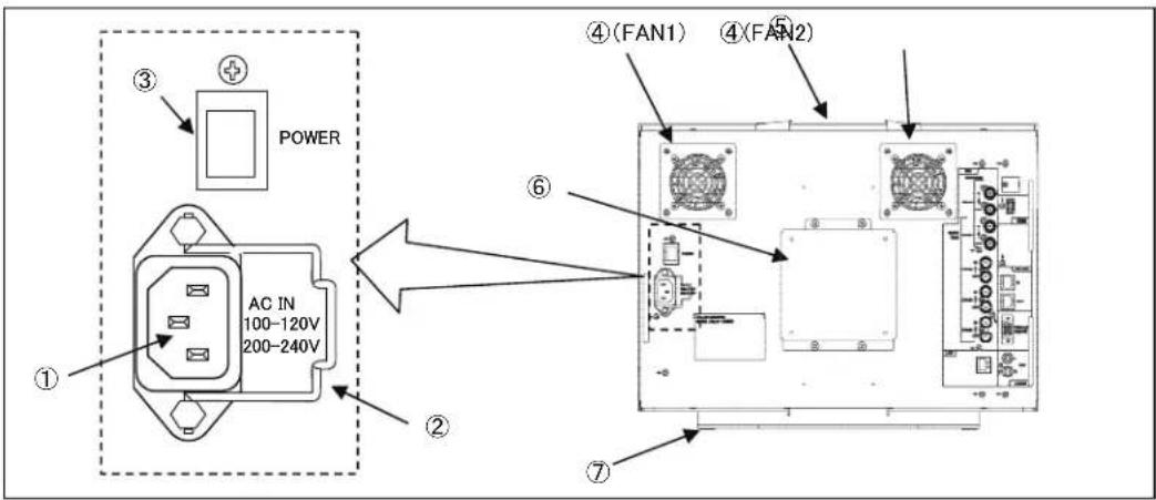
① AC power input
- Insert an AC cable here to supply AC power.
② Lock
• After inserting an AC plug, lock the AC plug with this lock to prevent it from disconnecting.
③ MAIN POWER switch
• Turns on/off the AC power supply to the monitor.
- To operate the monitor, turn ON this MAINPOWER switch as well as the POWER switch on the front panel.
④ Fan1/2
- When power is turned on, the fan starts running for the operational check. Then, it automatically operates according to the internal temperature.
When the fan does not start operating even the set temperature to start fan operation is reached, the following message is displayed on the screen.
FAN1 ERROR! : FAN on the left side as seen
from the
FAN2 ERROR! : FAN on the right side as seen
from the
⑤ Handle (option)
- This is an optional handle dedicated for this system.
- For details, refer to "10.2 Fixed stand STD-1720 (option) and handle GR-1720 (option)."
⑥ VESA Mount
- VESA mount of "100 x 100mm" or "200 x 100mm" can be installed here.
⑦ Fixed stand (option)
- This is an optional stand dedicated for this system.
- For details, refer to "10.2 Fixed stand STD-1720 (option) and handle GR-1720 (option)".
◆PRECAUTION
- Connect the power cord included with this unit to a 3-pin outlet with ground terminal. back
back

natural_image
Two types of electrical plugs: a two-pin socket and a three-pin plug (no text or symbols)2-3. Rear panel (video inputs/outputs)

① SDI CH-A1(12G/3G/HD) singal input and output
- A 12G/3G/HD signal is input to the "IN" connector.
- The input signal format is automatically detected.
- The input signal is output from the "OUT" connector by an active loop through.
② SDI CH-B1(12G/3G/HD) singal input and output
- A 12G/3G/HD signal is input to the "IN" connector.
- The input signal format is automatically detected.
- The input signal is output from the "OUT" connector by an active loop through.
③ SDI CH-B2(3G/HD) singal input and output
• A 3G/HD signal is input to the "IN" connector.
- The input signal format is automatically detected.
- The input signal is output from the "OUT" connector by an active loop through.
④ SDI CH-B3(3G/HD) singal input and output
- A 3G/HD signal is input to the "IN" connector.
- The input signal format is automatically detected.
- The input signal is output from the "OUT" connector by an active loop through.
⑤ SDI CH-B4(3G/HD) singal input and output
- A3G/HD signal is input to the "IN" connector.
• The input signal format is automatically detected. - The input signal is output from the "OUT" connector by an active loop through.
Supplementary explanation
* When displaying 4K images, input 12G signal in SDI CH-A1 or CH-B1. Or input a signal of the following Quad Link 4K by using four channels of CH-B1 to CH-B4.
CH-B1 Sub Image 1
CH-B2 Sub Image 2
CH-B3 Sub Image 3
CH-B4 Sub Image 4
Reference standards: SMPTE ST425-5, ST274, ST2018-2
CH-B1 Upper left
CH-B2 Upper right
CH-B3 Lower left
CH-B4 Lower right
* In case of the multiple screen display, up to four screens can be displayed from SDI CH-B1 through CH-B4 images.
⑥ Ethernet
- When controlling by Ethernet, connect a LAN cable to this connector.
⑦ HDMI signal input
- Input an HDMI signal (HDCP compatible) here.
⑧ RS-485 connection
- Remote control from the optional serial remote controller "SRC-400" is possible.
- Controlling "TSL UMD Protocol V3.1" is possible.
- When not connecting by a loop through, use a terminator.
- Set the monitor ID number from "000 to 126" at "MENU · UMD/IMD · TSL MONITOR ID."
- For the set items, refer to "4-11. Functions of MENU-UMD/IMD."
⑨ PARALLEL REMOTE signal input
- Connect the accompanying remote connector here.
- Use shielded wire for the cable.
- For the setting items, refer to "4-10. Function explanation of MENU - P.REMOTE".
⑩ Analog Audio output
- The embedded audio output channel signal set to MENU-AUDIO-LINE/SP CH is output as an analog audio signal (stereo).
Reference
a) Cables for 12G-SDI signal
In case of 12G-SDI transmission, the quality of coaxial cable has great impact. Bent and/or stamped cable, and age deterioration of the GND shield may generate impedance mismatch.
Bending, stepping on, or age deterioration of the cable may lead to such condition.
In this type of coaxial cable, transmission error may occur even in a short cable.
If a transmission error is displayed on the screen, use a new coaxial cable and try again.
* Recommended coaxial cable: L-5.5CUHD by Canare Electric Co., Ltd.
b) HDMI cable
In case of a HD signal, use the "High Speed" type HDMI cable. In case of 4K signal, use the "Premium High Speed" type HDMI cable. Use a cable which is 3m or shorter.
Also HDMI cables deteriorate due to bending, being flattened, and age deterioration. If the images are not displayed properly, use a new HDMI cable and retry.
2-4. External control
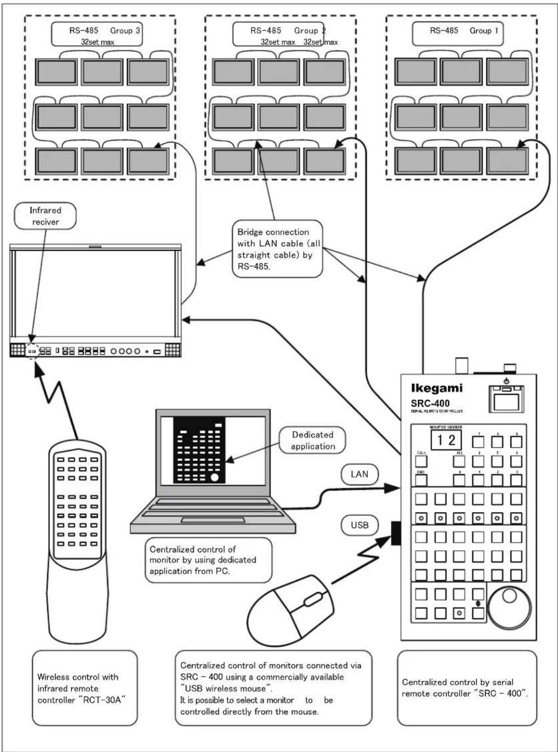
flowchart
graph TD
    subgraph_RS-485_Group_1["RS-485 Group 1"]
        A["Infrared receiver"] --> B["Laptop with monitor"]
        C["RS-485 Group 2"] --> D["Bridge connection with LAN cable (all straight cable) by RS-485."]
        E["RS-485 Group 3"] --> F["Infrared max"]
    end

    subgraph_Ikegami_SRC-400["Ikegami SRC-400"]
        G["Centralized control of monitor by using dedicated application from PC."] --> H["Laptop with monitor"]
        I["Centralized control of monitors connected via SRC - 400 using a commercially available "USB wireless mouse". It is possible to select a monitor to be controlled directly from the mouse."]
        J["Centralized control by serial remote controller "SRC - 400"."]
    end

    B --> H
    H --> K["USB"]
    K --> L["Mouse"]
    L --> M["Centralized control of monitor by using dedicated application from PC."]
    M --> N["Dedicated application"]
    N --> O["Ikegami SRC-400 Monitor AVUSTRER 12"]
    O --> P["Centralized control of monitors connected via SRC - 400 using a commercially available "USB wireless mouse". It is possible to select a monitor to be controlled directly from the mouse."]
    style RS-485_Group_1 fill:#f9f,stroke:#333
    style Ikegami_SRC-400 fill:#ccf,stroke:#333
3. Markers
3-1. Types of Markers
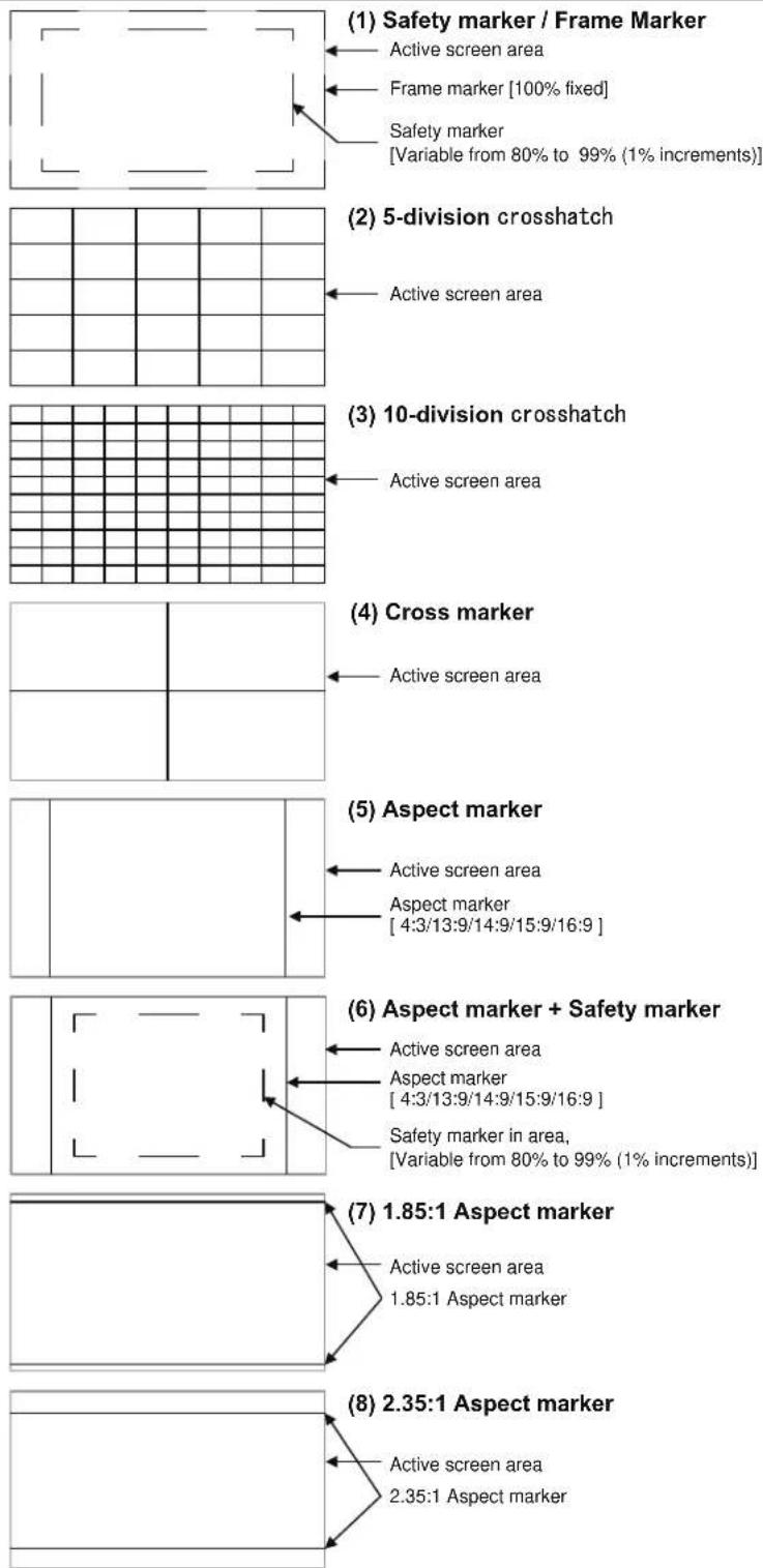
Active screen area
Frame marker [100% fixed]
Safety marker
[Variable from 80% to 99% (1% increments)]
Active screen area
Active screen area
Active screen area
Active screen area
Aspect marker
[4:3/13:9/14:9/15:9/16:9]
Active screen area
Aspect marker
[4:3/13:9/14:9/15:9/16:9]
Safety marker in area,
[Variable from 80% to 99% (1% increments)]
Active screen area
1.85:1 Aspect marker
Active screen area
2.35:1 Aspect marker
- The displayed markers are set in "MENU-MARKER".
- There are two kinds of settings (1): "FRM + SAFE" with frame marker and "SAFETY" without frame marker. The figure in (1) is the setting state of "FRM + SAFE".
4. MENU Functions
4-1. MENU Outline

flowchart
graph TD
    A["Data registration"] --> B["Data change"]
    B --> C["Data registration"]
    C --> D["Menu"]
    D --> E["ESO"]
    E --> F["Normal screen"]

    subgraph Data registration
        G["Video Audio TOWMUSIC MARKER UTILITY FUNC.SW P.REMOTE UNIDMO C.CAPTION USB NETWORK RESET INFO EXIT"]
    end

    subgraph Data change
        H["Video Audio TOWMUSIC MARKER UTILITY FUNC.SW P.REOTE UNIDMO C.CAPTION USB NETWORK RESET INFO EXIT"]
    end

    subgraph Data registration
        I["Video Audio TOWMUSIC MARKER UTILITY FUNC.SW P.REOTE UNIDMO C.CAPTION USB NETWORK RESET INFO EXIT"]
    end

    subgraph Data change
        J["Video Audio TOWMUSIC MARKER UTILITY FUNC.SW P.REOTE UNIDMO C.CAPTION USB NETWORK RESET INFO EXIT"]
    end

    subgraph Data registration
        K["Video Audio TOWMUSIC MARKER UTILITY FUNC.SW P.REOTE UNIDMO C.CAPTION USB NETWORK RESET INFO EXIT"]
    end

    subgraph Data change
        L["Video Audio TOWMUSIC MARKER UTILITY FUNC.SW P.REOTE UNIDMO C.CAPTION USB NETWORK RESET INFO EXIT"]
    end

    subgraph Data registration
        M["Video Audio TOWMUSIC MARKER UTILITY FUNC.SW P.REOTE UNIDMO C.CAPTION USB NETWORK RESET INFO EXIT"]
    end

    subgraph Data change
        N["Video Audio TOWMUSIC MARKER UTILITY FUNC.SW P.REOTE UNIDMO C.CAPTION USB NETWORK RESET INFO EXIT"]
    end

    subgraph Data registration
        O["Video Audio TOWMUSIC MARKER UTILITY FUNC.SW P.REOTE UNIDMO C.CAPTION USB NETWORK RESET INFO EXIT"]
    end

    subgraph Data change
        P["Video Audio TOWMUSIC MARKER UTILITY FUNC.SW P.REOTE UNIDMO C.CAPTION USB NETWORK RESET INFO EXIT"]
    end

    subgraph Data registration
        Q["Video Audio TOWMUSIC MARKER UTILITY FUNC.SW P.REOTE UNIDMO C.CAPTION USB NETWORK RESET INFO EXIT"]
    end

    subgraph Data change
        R["Video Audio TOWMUSIC MARKER UTILITY FUNC.SW P.REOTE UNIDMO C.CAPTION USB NETWORK RESET INFO EXIT"]
    end

    subgraph Data registration
        S["Video Audio TOWMUSIC MARKER UTILITY FUNC.SW P.REOTE UNIDMO C.CAPTION USB NETWORK RESET INFO EXIT"]
    end

    subgraph Data change
        T["Video Audio TOWMUSIC MARKER UTILITY FUNC.SW P.REOTE UNIDMO C.CAPTION USB NETWORK RESET INFO EXIT"]
    end

    subgraph Data registration
        U["Video Audio TOWMUSIC MARKER UTILITY FUNC.SW P.REOTE UNIDMO C.CAPTION USB NETWORK RESET INFO EXIT"]
    end

    subgraph Data change
        V["Video Audio TOWMUSIC MARKER UTILITY FUNC.SW P.REOTE UNIDMO C.CAPTION USB NETWORK RESET INFO EXIT"]
    end

    subgraph Data registration
        W["Video Audio TOWMUSIC MARKER UTILITY FUNC.SW P.REOTE UNIDMO C.CAPTION USB NETWORK RESET INFO EXIT"]
    end

    subgraph Data change
        X["Video Audio TOWMUSIC MARKER UTILITY FUNC.SW P.REOTE UNIDMO C.CAPTION USB NETWORK RESET INFO EXIT"]
    end

    subgraph Data registration
        Y["Video Audio TOWMUSIC MARKER UTILITY FUNC.SW P.REOTE UNIDMO C.CAPTION USB NETWORK RESET INFO EXIT"]
    end

    subgraph Data change
        Z["Video Audio TOWMUSIC MARKER UTILITY FUNC.SW P.REOTE UNIDMO C.CAPTION USB NETWORK RESET INFO EXIT"]
    end

    subgraph Data registration
        AA["Video Audio TOWMUSIC MARKER UTILITY FUNC.SW P.REOTE UNIDMO C.CAPTION USB NETWORK RESET INFO EXIT"]
    end

    subgraph Data change
        AB["Video Audio TOWMUSIC MARKER UTILITY FUNC.SW P.REOTE UNIDMO C.CAPTION USB NETWORK RESET INFO EXIT"]
    end

    subgraph Data registration
        AC["Video Audio TOWMUSIC MARKER UTILITY FUNC.SW P.REOTE UNIDMO C.CAPTION USB NETWORK RESET INFO EXIT"]
    end

    subgraph Data change
        AD["Video Audio TOWMUSIC MARKER UTILITY FUNC.SW P.REOTE UNIDMO C.CAPTION USB NETWORK RESET INFO EXIT"]
    end

    subgraph Data registration
        AE["Video Audio TOWMUSIC MARKER UTILITY FUNC.SW P.REOTE UNIDMO C.CAPTION USB NETWORK RESET INFO EXIT"]
    end

    subgraph Data change
        AF["Video Audio TOWMUSIC MARKER UTILITY FUNC.SW P.REOTE UNIDMO C.CAPTION USB NETWORK RESET INFO EXIT"]
    end

    subgraph Data registration
        AG["Video Audio TOWMUSIC MARKER UTILITY FUNC.SW P.REOTE UNIDMO C.CAPTION USB NETWORK RESET INFO EXIT"]
    end

    subgraph Data change
        AH["Video Audio TOWMUSIC MARKER UTILITY FUNC.SW P.REOTE UNIDMO C.CAPTION USB NETWORK RESET INFO EXIT"]
    end

    subgraph Data registration
        AI["Video Audio TOWMUSIC MARKER UTILITY FUNC.SW P.REOTE UNIDMO C.CAPTION USB NETWORK RESET INFO EXIT"]
    end

    subgraph Data change
        AJ["Video Audio TOWMUSIC MARKER UTILITY FUNC.SW P.REOTE UNIDMO C.CAPTION USB NETWORK RESET INFO EXIT"]
    end

    subgraph Data registration
        AK["Video Audio TOWMUSIC MARKER UTILITY FUNC.SW P.REOTE UNIDMO C.CAPTION USB NETWORK RESET INFO EXIT"]
    end

    subgraph Data change
        AL["Video Audio TOWMUSIC MARKER UTILITY FUNC.SW P.REOTE UNIDMO C.CAPTION USB NETWORK RESET INFO EXIT"]
    end

    subgraph Data registration
        AM["Video Audio TOWMUSIC MARKER UTILITY FUNC.SW P.REOTE UNIDMO C.CAPTION USB NETWORK RESET INFO EXIT"]
    end

    subgraph Data change
        AN["Video Audio TOWMUSIC MARKER UTILITY FUNC.SW P.REOTE UNIDMO C.CAPTION USB NETWORK RESET INFO EXIT"]
    end

    subgraph Data registration
        AO["Video Audio TOWMUSIC MARKER UTILITY FUNC.SW P.REOTE UNIDMO C.CAPTION USB NETWORK RESET INFO EXIT"]
    end

    subgraph Data change
        AP["Video Audio TOWMUSIC MARKER UTILITY FUNC.SW P.REOTE UNIDMO C.CAPTION USB NETWORK RESET INFO EXIT"]
    end

    subgraph Data registration
        AQ["Video Audio TOWMUSIC MARKER UTILITY FUNC.SW P.REOTE UNIDMO C.CAPTION USB NETWORK RESET INFO EXIT"]
    end

    subgraph Data change
        AR["Video Audio TOWMUSIC MARKER UTILITY FUNC.SW P.REOTE UNIDMO C.CAPTION USB NETWORK RESET INFO EXIT"]
    end

    subgraph Data registration
        AS["Video Audio TOWMUSIC MARKER UTILITY FUNC.SW P.REOTE UNIDMO C.CAPTION USB NETWORK RESET INFO EXIT"]
    end

    subgraph Data change
        AT["Video Audio TOWMUSIC MARKER UTILITY FUNC.SW P.REOTE UNIDMO C.CAPTION USB NETWORK RESET INFO EXIT"]
    end

    subgraph Data registration
        AU["Video Audio TOWMUSIC MARKER UTILITY FUNC.SW P.REOTE UNIDMO C.CAPTION USB NETWORK RESET INFO EXIT"]
    end

    subgraph Data change
        AV["Video Audio TOWMUSIC MARKER UTILITY FUNC.SW P.REOTE UNIDMO C.CAPTION USB NETWORK RESET INFO EXIT"]
    end

    subgraph Data registration
        AW["Video Audio TOWMUSIC MARKER UTILITY FUNC.SW P.REOTE UNIDMO C.CAPTION USB NETWORK RESET INFO EXIT"]
    end

    subgraph Data change
        AX["Video Audio TOWMUSIC MARKER UTILITY FUNC.SW P.REOTE UNIDMO C.CAPTION USB NETWORK RESET INFO EXIT"]
    end

    subgraph Data registration
        AY["Video Audio TOWMUSIC MARKER UTILITY FUNC.SW P.REOTE UNIDMO C.CAPTION USB NETWORK RESET INFO EXIT"]
    end

    subgraph Data change
        AZ["Video Audio TOWMUSIC MARKER UTILITY FUNC.SW P.REOTE UNIDMO C.CAPTION USB NETWORK RESET INFO EXIT"]
    end

    subgraph Data registration
        BA["Video Audio TOWMUSIC MARKER UTILITY FUNC.SW P.REOTE UNIDMO C.CAPTION USB NETWORK RESET INFO EXIT"]
    end

    subgraph Data change
        BB["Video Audio TOWMUSIC MARKER UTILITY FUNC.SW P.REOTE UNIDMO C.CAPTION USB NETWORK RESET INFO EXIT"]
    end

    subgraph Data registration
        BC["Video Audio TOWMUSIC MARKER UTILITY FUNC.SW P.REOTE UNIDMO C.CAPTION USB NETWORK RESET INFO EXIT"]
    end

    subgraph Data change
        DA["Video Audio TOWMUSIC MARKER UTILITY FUNC.SW P.REOTE UNIDMO C.CAPTION USB NETWORK RESET INFO EXIT"]
    end

    subgraph Data registration
        AE["Video Audio TOWMUSIC MARKER UTILITY FUNC.SW P.REOTE UNIDMO C.CAPTION USB NETWORK RESET INFO EXIT"]
    end

    subgraph Data change
        AF[Video Audio TOWMUSIC MARKER UTILITY FUNC.SW P.REOTE √RND VSX10000000000000000000000000000000000000000000000000000000000000000000000000000000000000000000000000000 |

    direction TB
4-2. Description of MENU-INPUT Functions

flowchart
graph TD
    A["4K/2K/MULTI"] --> B["VIEW MODE"]
    A --> C["In MULT MODE"]
    B --> D["VIDEO SOURCE"]
    B --> E["SDI-B1/2/3/4"]
    B --> F["SDI-A1 SELECT"]
    B --> G["SDI-B1 SELECT"]
    B --> H["SDI-B1/2/3/4 SELECT"]
    B --> I["HDMI SELECT"]
    B --> J["IMAGE DIVISION"]
    B --> K["SDI STRUCTURE"]
    B --> L["SDI RANGE"]
    B --> M["HDMI(DVI) FORMAT"]
    B --> N["INPUT LOCK"]
    B --> O["MIX TEST SIGNAL"]
    B --> P["RETURN"]
    C --> Q["Multi MODE"]
    C --> R["Multi Pattern"]
    C --> S["SYNC MODE"]
    C --> T["SRC GROUP"]
    C --> U["SDI ONLY"]
    C --> V["Multi MODE"]
    C --> W["Multi MODE"]
    C --> X["Multi MODE"]
    C --> Y["Multi MODE"]
    C --> Z["Multi MODE"]
    C --> AA["Multi MODE"]
    C --> AB["Multi MODE"]
    C --> AC["Multi MODE"]
    C --> AD["Multi MODE"]
① VIEW MODE setting
- Set the combination of switching input signals.
4K MODE Current mode 2K MODE Switches to the 2K mode. MULTI MODE Switches to the MULTI mode.
- Default setting is 4K MODE.
② 4K MODE VIDEO SOURCE setting
- Following items can be selected when VIEW MODE is 4K MODE.
SDI-A1
SDI-B1
SDI-B1/B2/B3/B4 (Quad Link) HDMI
- In case of SDI-B1/B2/B3/B4, check four SDI cables are input.
- Default is SDI-B1/B2/B3/B4.
③ 4K MODE SDI-A1 SELECT setting
- Setting ENABLE and DISABLE is possible. When DISABLE is set, CH-A1 is skipped by the transition of the front INPUT switch.
- Default is ENABLE.
④ 4 K MODE SDI-B1 SELECT setting
- Setting ENABLE and DISABLE is possible. When DISABLE is set, CH-B1 is skipped by the transition of the front INPUT switch.
- Default is ENABLE..
⑤ 4K MODE SDI-B1/2/3/4 SELECT setting
- Setting ENABLE and DISABLE is possible. When DISABLE is set, Quad Link 4K which uses four channels of CH-B1 to CH-B4 is skipped by the transition of the front INPUT switch.
- Default is ENABLE..
⑥ 4K MODE HDMI SELECT setting
- Setting ENABLE and DISABLE is possible. When DISABLE is set, HDMI is skipped by the transition of the front INPUT switch.
- Default is ENABLE..
⑦ 4K MODE IMAGE DIVISION setting
- The CH-B1/B2/B3/B4 signal type can be selected from the following items when VIEW MODE is 4K MODE.
AUTO Automatic judgment SQUARE Two-by-two matrix divide 2SI 2 Sample Interleave
- Default is AQUARE.
⑧ MULTI MODE VIEW MODE setting
- Set the combination of switching input signals.
MULTI MODE Current mode
4K MODE Switches to the 4K mode.
2K MODE Switches to the 2K mode.
⑨ MULTI MODE MULTIPATTERN setting
- The inputs CH-B1, CH-B2, CH-B3, and CH-B4 are displayed in the tetrameric areas in the 4K-size screen as follows.
4 MULTI

3 MULTI

2 MULTI

* Above condition is obtained when item ⑦ MULTI MODE SRC GROUP setting is SDI ONLY.
* In case of the interlace signal, some image contents may show a horizontal line at the boundary of each screen. This is due to the process corresponding to the IP conversion.
- Default is 4 MULTI.
⑩ MULTI MODE SYNC MODE setting
• SYNCHRONOUS
When synchronization of inputs CH-B1, CH-B2, CH-B3, and CH-B4 is known, set this mode.
Low delay mode.
• ASYNCHRONOUS.
When inputs CH-B1, CH-B2, CH-B3, and CH-B4 are asynchronous, set this mode. The display delays; however, disturbance of video images by asynchronous can be resolved.
- Default is SYNCRONOUS.
⑪ MULTI MODE SRC GROUP setting
- When 4 MULTI SDI ONLY CH-B1, CH-B2, CH-B3, CH-B4 SDI + HDMI CH-B1, CH-B2, CH-B3, HDMI The 4th screen becomes HDMI instead of CH-B4.
- When 3 MULTI SDI ONLY CH-B1, CH-B2, CH-B3 SDI + HDMI CH-B1, CH-B2, HDMI SDI + HDMI CH-B1, CH-B2, and HDMI The 3rd screen becomes HDMI instead of CH-B3.
- When 2 MULTI SDI ONLY CH-B1, CH-B2 SDI + HDMI CH-B1, HDMI The 2nd screen becomes HDMI instead of CH-B2.
- Default is SDI ONLY.
⑫ 2K MODE VIEW MODE setting
- Set the combination of switching input signals. 2K MODE (Current setting) MULTI MODE 4K MODE
⑬ 2K MODE VIDEO SOURCE setting
- Following items can be selected when VIEW MODE is 2K MODE.
SDI-A1
SDI-B1
SDI-B2
SDI-B3
SDI-B4
HDMI
- Default is SDI-B1.
⑭ 2K MODE SDI-A1 SELECT setting
- It is fixed to ENABLE. - Skipping CH-A1 by the transition of the front INPUT switch is not possible.
⑮ 2K MODE SDI-B1 SELECT setting
- When DISABLE is set, CH-B1 is skipped by transition of the front INPUT switch. - Default is ENABLE.
⑯ 2K MODE SDI-B2 SELECT setting
- When DISABLE is set, CH-B2 is skipped by transition of the front INPUT switch. - Default is ENABLE.
⑰ 2K MODE SDI-B3 SELECT setting
- When DISABLE is set, CH-B3 is skipped by transition of the front INPUT switch. - Default is ENABLE.
⑱ 2K MODE SDI-B4 SELECT setting
- When DISABLE is set, CH-B4 is skipped by transition of the front INPUT switch.
- Default is ENABLE.
⑲ 2K MODE HDMI SELECT setting
- When DISABLE is set, HDMI is skipped by transition of the front INPUT switch.
- Default is ENABLE.
⑳ SDI STRUCTURE setting
- When an SDI signal without the payload information is input, the image may not be displayed properly since the necessary information is missing. In that case, the format of input signal has to be set. Select from a combination of the signal format (RGB/YCbCr), sampling structure (422/444), and bit width (10 bit/12 bit).
• AUTO : Automatic selection
· YCbCr422/10 : 422 color difference signal 10 bit
- YCbCr444/10 : 444 color difference signal 10 bit
- YCbCr444/12 : 444 color difference signal 12 bit
- RGB444/10 : 444 RGB signal 10 bit
· RGB444/12 : 444 RGB signal 12 bit
- In addition to this setting, the setting of ② SDI RANGE might be necessary.
- Default is AUTO.
When there is no payload information in AUTO, processing of YCbCr422/10 is conducted.
Note 1
- If SDI STRUCTURE is set to AUTO when the payload information is incorrect for the image, "Image not output / Menu not displayed / Menu flickering" may occur.
In this case, press the TEST switch and with the internal TEST signal being displayed, set the SDI STRUCTURE to match the input image.
Note 2
- When VIEW MODE is set to 4K MODE and if an image judged to be 4K PsF format is input, the image will only be output with SDI STRUCTURE is set to AUTO. Settings other than AUTO will judge it as NoSync and the operation will not output the image.
②1 SDI RANGE setting
- When an SDI signal without the payload information is input, the image may not be displayed properly since the necessary information is missing. In that case, the following signal range setting may be required in addition to ② SDI STRUCTURE setting.
· AUTO : Automatic selection
• LIMITED : 64 to 940 (bit width when 10 bit)
- SDI FULL : 4 to 1019 (bit width when 10 bit)
- Default is AUTO.
When there is no payload information in AUTO, processing of LIMITED is conducted.
② HDMI (DVI) FORMAT setting
- When the DVI signal (2K/HD) is input to the HDMI input terminal, specify RGB or YPbPr here, since the DVI signal does not have RGB/YPbPr information.
- Default is RGB.
②3 INPUT LOCK setting
- When preventing the switching of the input channel, set to "ON" to fix the input channel.
- Default is OFF.
⑳ MIX TEST SIGNAL
- EXECUTE
• MIX TEST SIGNAL is displayed.
While MIX TEST SIGNAL is displayed, executing EXCUTE again hides the MIX TEST SIGNAL.
In addition, it becomes hidden after one minute from the first display.
4-3. Description of MENU-VIDEO Functions

① Setting the chroma gain-up ON/OFF
- Set the gain-up ON/OFF for chroma.
- When Chroma Gain Up is On the chroma Default setting is 16, increases by “+9 dB or +12dB”.
- This function can be assigned to a function switch on the front panel.
- Default setting is OFF.
② Setting the gain-up level (9db/12dB)
- Sets the Chroma Gain Up level.
- Selects the Chroma Gain Up level from "+9dB or +12dB".
- Default setting is 12dB.
③ Setting the scan mode (NORMAL/NATIVE)
- While the input signal is 2K signal, switch the mode which is converted up to 4K.
NORMAL : Scaler indication Display by interpolating by the filter
NATIVE : Doubler indication Display the same pixels for two-by-two in row and line.
- Default setting is NORMAL.
④ Setting the REAL SCAN ON/OFF
- In case of ON, if the input signal is 2K signal, the image is displayed in the middle of the screen without enlarging or downsizing and without resizing (with original number of pixels).
* MARKER turns to OFF.
- Default setting is OFF.
⑤ Setting the APERTURE ON/OFF
- Set the APERTURE ON/OFF.
- This function can be assigned to a function switch on the front panel.
- Default setting is OFF.
⑥ Setting the APERTURE LEVEL
- Set the APERTURE level in the range from 1 to 63.
a Default setting is 16.
⑦ Setting the APERTURE frequency
- Set the boost frequency of APERTURE.
- LOW Boost from around 10MHz
• MID1 Boost from around 15MHz
· MID2 Boost from around 20MHz
• HIGH Boost from around 25MHz
- Default setting is HIGH.
⑧ Setting the IP conversion mode
- It sets the movie detection mode when the interlace signal is displayed by converting to progressive.
MOTION : Movie level high STILL : Movie level low (lower than still image)
- Default setting is MOTION.
4-4. Description of MENU AUDIO Functions

① Setting the channels of embedded audio for output
- Set any of the following pairs of channels of embedded audio to be output to the front speaker and the headphone jack.
- CH1/2\~CH15/16
In the case of CH1/2, outputs a pair channel of CH1 and CH2.
- DOWNMIX
Downm
ix from 5.1 ch surround sound.
- This function can be assigned to a function switch on the front panel.
- When HDMI is selected as an image input, setting CH9/10 through CH15/16 means that CH1/2 through CH7/8 are selected.
Indication → Actual selected channel
CH9/10 → CH1/2
CH11/12 → CH3/4
CH13/14 → CH5/6
CH15/16 → CH7/8
- Default setting is CH1/2.
② Audio selection when the Multiple screen is displayed MULTI SELECT
- When in the Multi screen mode, set one screen to output audio out of two to four divided screens.
- Default setting is DISABLE.
③ Setting the audio level meter display ON/OFF
• Used to turn on and off the audio level meter display.
- Default setting is OFF.
④ Setting the display mode of audio level metering
- Set the display mode of the audio level meter.
• The number in parentheses shows the order of displayed channels.
- MODES 5 to 8 are obtained by doubling the width of MODES 1 to 4.
• MODE1 (1357-2468)

• MODE2 (1234-5678)
MODE3 (1357-8642)
MODE4 (12-34) : During the display mode
1-2ch and 1-4ch settings.
MODE4 (1234-5678) : During the display mode
1-8ch settings.
* The display of MODE 4 varies depending on the number of channels for the section ⑤.
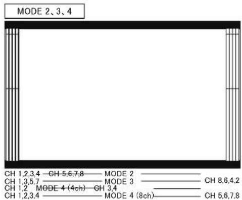
HQLM-1720WR
• MODE5 (1357-2468)
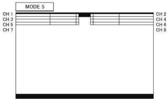
• MODE6 (1234-5678)
MODE7 (1357-8642)
MODE8 (12-34) : During the display mode 1-2ch and
MODE8 (1234-5678) : During the display mode 1-8ch
* The display of MODE 4 varies depending on the number of channels for the section ⑤.
MODE 6、7、8

- Default setting is 1(1357-2468).
⑤ Setting the channel display of the audio level meter
- The display channel of the audio level meter is set. Within embedded audio 16 channels, up to 8 channels are allocated as follows.
- CH 1-2:CH1 to CH2 is displayed.
- CH 1-4:CH1 to CH4 is displayed.
- CH 1-8:CH1 to CH8 is displayed.
- CH 9-10:CH1 to CH2 is displayed.
- CH 9-12:CH1 to CH4 is displayed.
- CH 9-16:CH1 to CH8 is displayed.
- Default setting is CH 1-8.
⑥ Setting the brightness of the audio level meter
- Set the brightness of the audio level meter.
- The level meter image transmissive mode or nontransmissive mode can be set.
· LOW
• MID
· HIGH - LOW (MIX) (Image transmissive mode)
• MID (MIX) (Image transmissive mode)
• HIGH (MIX) (Image transmissive mode)
- Default setting is HIGH.
⑦ Setting the peak hold display of the audio level meter
• Used to turn on and off the peak hold display.
- Default setting is ON.
settings.
⑧ Setting the reference level
- Set the reference level of the audio level meter.
-18dBFS
-20dBFS
- Default setting is -20dBFS
⑨ Downmix setting
- Set the 5.1 channel surround downmix.
- Mix the 5.1 channel surround audio signal assigned to 6 channels of embedded audio into 2 channels, and output to the speaker, the headphone and the audio monitor output.
- 5.1ch surround sub woofer(LFE) channel is not mixed.
⑩ Setting the downmix formats
- Select the mixing method to downmix 5.1ch audio in "ISO/IEC" and "ARIB".
- Default setting is ISO/IEC
⑪ Setting the Ls/Rs level
- Set the coefficient of Ls / Rs to mix.
- Set among -3dB/-6dB/-9dB/OFF.
$$ (O F F = - \infty) $$
- Default setting is -3dB
⑫ Setting the embedded audio channel assignment of speaker (Lm)
- Set which embedded audio channel is allocated to the 5.1-ch surround Lm speaker (left side in front).
- Default setting is CH1
⑬ Setting the embedded audio channel assignment of speaker (Rm)
- Set which embedded audio channel is allocated to the 5.1-ch surround Rm speaker (right side in front).
- Default setting is CH2
⑭ Setting the embedded audio channel assignment of speaker (C)
- Set which embedded audio channel is allocated to the 5.1-ch surround C speaker (center).
- Default setting is CH3
⑮ Setting the embedded audio channel assignment of speaker (Ls)
- Set which embedded audio channel is allocated to the 5.1-ch surround Ls speaker (left side in rear).
- Default setting is CH5
⑯ Setting the embedded audio channel assignment of speaker (Rs)
- Set which embedded audio channel is allocated to the 5.1-ch surround Rs speaker (right side in rear).
- Default setting is CH6
4-5. Description of MENU-TC/WFM/VSC Functions
* TC / WFM / VSC is supported for HD/3G/12G SDI signals.
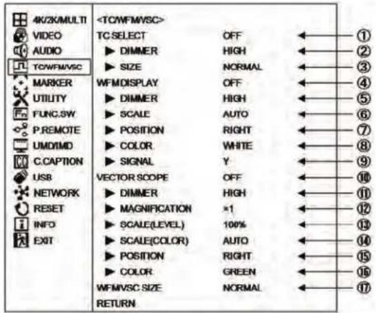
① Setting the SDI TC display ON/OFF
• Used to turn ON or OFF the VITC/LTC display multiplexed with the ANC part of the signal.
. This function can be assigned to a function switch on the front panel.
- Default setting is OFF.
② Setting of SDI TC display brightness
• Used to set the SDI TC display brightness in three levels, LOW, MID and HIGH.
- Default setting is MID.
③ Setting of SDI TC display size
• Used to select the SDI TC display size, NORMAL or LARGE.
- Default setting is NORMAL.

NORMAL

LARGE
④ Setting of waveform display ON/OFF
• Used to turn ON or OFF the waveform display of luminance signal.
. This function can be assigned to a function switch on the front panel.
- Default setting is OFF.
⑤ Setting of waveform display brightness
• Used to set the waveform display brightness in three levels, LOW, MID, HIGH and HIGH(M).
- HIGH(M) mode displays the picture with WFM overlay.
- Default setting is HIGH.
⑥ Setting of waveform display size
- The waveform display scale can be set to AUTO, SDR, HLG, or PQ.
- Default setting is AUTO.
⑦ Setting of waveform display position
. Used to set the waveform display position, RIGHT or LEFT.
- Default setting is RIGHT.
⑧ Setting the waveform display color
• Used to set the waveform display color, WHITE or COLOR.
- For COLOR settling, it is displayed in the following colors.
- Default setting is WHITE.
⑨ Selection of SIGNAL waveform display CH
- Select the waveform channels to display from R, G, B, RGB, Y, Cb, Cr, and YCrCb.
- In the RGB waveform display mode, when the input terminal signal is YCbCr, the levels may be displayed out of position due to an operational error of the matrix.
- Default setting is Y.
⑩ Setting the VSC (VECTOR SCOPE) display ON/OFF
- Used to turn on or off the VECTOR SCOPE display.
. This function can be assigned to a function switch on the front panel.
- Default setting is OFF.
⑪ Setting the VSC (VECTOR SCOPE) display brightness
. Used to set the VECTOR SCOPE display brightness in 3 levels: LOW, MID, HIGH and HIGH(M).
- HIGH(M) mode displays the picture with VSC overlay.
- Default setting is HIGH.
⑫ Setting the VECTOR SCOPE display magnification ratio
• Used to set the VECTOR SCOPE display magnification in 4 ratios: x1, x2, x4 and x8.
- Default setting is x1.
⑬ Setting the COLOR BOX scale display
- Used to set the VECTOR SCOPE's COLOR BOX according to the input color bar signal: 75% or 100%.
- Default setting is 100%.

natural_image
Four quadrants divided into four equal sections with scattered square markers (no text or symbols)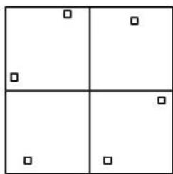
natural_image
Simple 2x2 grid with four quadrants and scattered squares (no text or symbols)75% SCALE 100% SCALE
⑭ Setting the COLOR BOX scal display (color space)
- Used to set the VECTOR SCOPE's COLOR BOX according to color space of the input signal: AUTO, BT709 and BT2020.
- Default setting is AUTO.
⑮ Setting the VSC (VECTOR SCOPE) display position
- Used to set the vector display to either the RIGHT and LEFT positions.
- When used in common with the WFM, the VECTOR display is located on the left of the WFM one.
- Default setting is RIGHT.
• RIGHT location


- LEFT location


⑯ Setting the VECTOR SCOPE display color
• Used to set the vector display color to either of GREEN and WHITE.
- Default setting is GREEN.
⑰ Setting of VSC (VECTOR SCOPE) display size
• Used to set the VECTOR SCOPE display size to either of NORMAL and SMALL.
- Default setting is NORMAL.
4-6. Description of MENU-MARKER Functions
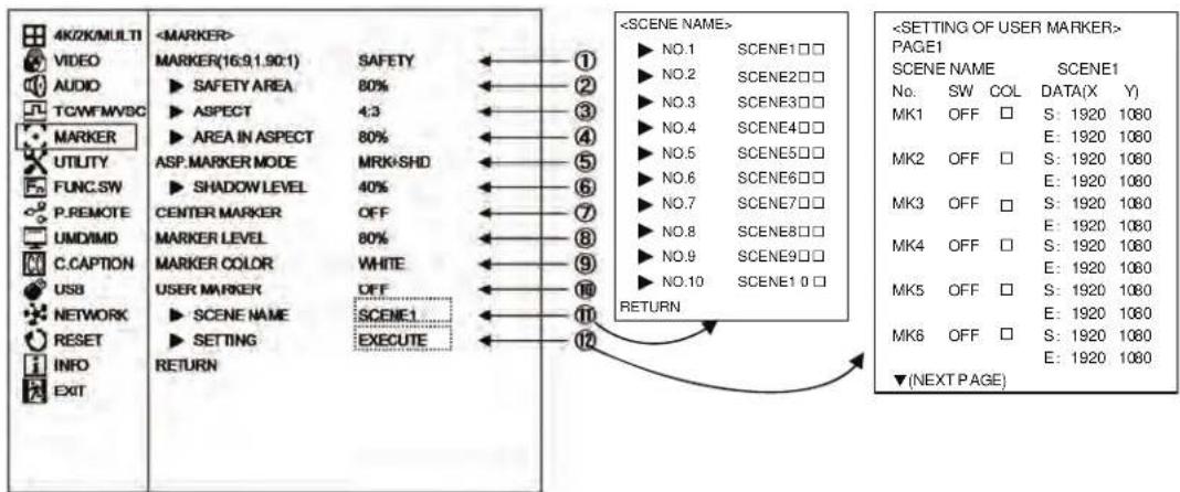
① Setting the type of marker
• Used to set various types of markers displayed.
- SAFETY : Displaying the safety marker preset in Item ②.
- CROSS5 : 5-split crosshatch pattern.
• CROSS10 : 10-split crosshatch pattern.
· C.CROSS : Cross marker.
- ASPECT : Displaying the aspect marker preset in Item ③.
- ASP+SAF : Displaying the aspect marker preset in Item ③ and the safety marker in aspect marker area preset in Item ④.
- This function can be assigned to a function switch on the front panel.
Default setting is SAFETY.

② Setting the safety marker area
• Used to set the safety marker area in the 80%-99% range with 1% increments.

- Default setting is 80% (safety area).
③ Setting the type of aspect marker
- Used to select the type of aspect marker from "4:3, 13:9, 14:9, 15:9, 1.85:1 and 2.35:1".
![Active screen area Aspect marker [4:3/13:9/14:9/15:9] Active screen area Aspect marker [1.85:1 / 2.35:1] • Default setting is 4:3 marker.](/content/2026/05/979870/images/2804a00a164637d86226d7ce6d2d0475dad7c961c860d796e8ffc783fd04c740.jpg)
④ Setting the safety marker area in aspect marker area
• Used to set the safety marker in the aspect marker (4:3, 13:9, 14:9 and 15:9) area in the 80%-99% range with 1% increments.
![Active screen area Aspect marker [ 4:3/13:9/14:9/15:9 ] Safety marker in area, variable from 80% to 99% (1% increments)](/content/2026/05/979870/images/d693e319cb1555f5c787aed95d8549481b544384d6f97d983f84e413c0e1364f.jpg)
- Default setting is 80% (safety area).
⑤ Setting the aspect marker display mode
• Used to set the aspect marker display mode.
- MARKER : Displaying the marker only.
- SHADOW : Displaying the shadow only
-
MRK+SHD : Displaying both the marker and shadow
-
Default setting is MARKER+SHADOW.

natural_image
Pure geometric shapes with no text, numbers, or symbolsSHADOWMARKER MRK+SHD
⑥ Setting the aspect marker shadow level
• Used to set the contrast level of the aspect marker shadow, when displayed.
- Settings: 0%, 20%, 40% and 60%
- Default setting is 40%.
⑦ Setting the center marker ON(TYPE-A/B)/OFF
• Used to turn on and off the center cross marker.
- There are two kinds of center markers TYPE-A or TYPE-B.
- Default setting is OFF.
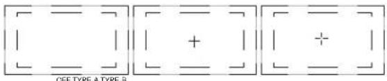
⑧ Setting the marker display level
• Used to set the marker display level.
- Settings: 20%, 40%, 60%, 80% and 100%
- Default setting is 80%.
⑨ Setting the marker display color
• Used to set the marker display color.
* The marker is displayed in the color preset on the marker menu.
- Settings : White, yellow, cyan, green, magenta, red and blue
- Default setting is white.
⑩ Setting the user marker display ON/OFF
• Used to turn on and off the user marker display.
- This function can be assigned to a function switch on the front panel.
- Default setting is OFF.
⑪ Selecting each scene of user markers and setting the scene names
- The user markers can be set for up to 10 scenes; you can select from SCENE 1 to SCENE 10.
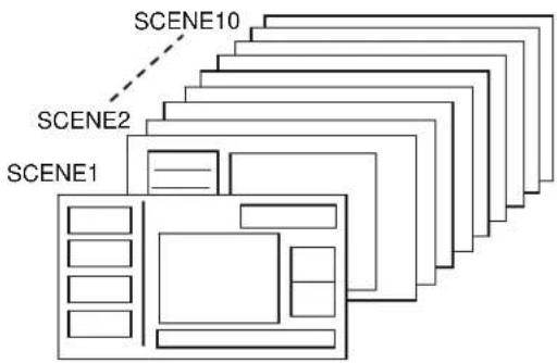
flowchart
graph TD
    A["SCENE1"] --> B["SCENE2"]
    B --> C["SCENE10"]
    style A fill:#f9f,stroke:#333
    style B fill:#bbf,stroke:#333
    style C fill:#dfd,stroke:#333
- The name of each scene can be up to 8 characters in length with the following characters: "0-9, A-Z, 0, -, □ (blank)".
- If you press ENT on the SCENE, the following SETTING MENU is displayed, and there you can change the name of each SCENE.
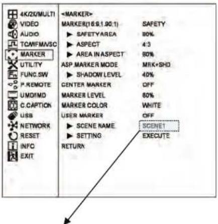

flowchart
graph LR
    A["<SCENE NAME>"] --> B["NO.1 SCENE1 □□"]
    A --> C["NO.2 SCENE2 □□"]
    A --> D["NO.3 SCENE3 □□"]
    A --> E["NO.4 SCENE4 □□"]
    A --> F["NO.5 SCENE5 □□"]
    A --> G["NO.6 SCENE6 □□"]
    A --> H["NO.7 SCENE7 □□"]
    A --> I["NO.8 SCENE8 □□"]
    A --> J["NO.9 SCENE9 □□"]
    A --> K["NO.10 SCENE1 0 □"]
    L["<SCENE NAME>"] --> M["NO.1 ABCDEFGH"]
    L --> N["NO.2 SCENE2□□"]
    L --> O["NO.3 SCENE3□□"]
    L --> P["NO.4 SCENE4□□"]
    L --> Q["NO.5 SCENE5□□"]
    L --> R["NO.6 SCENE6□□"]
    L --> S["NO.7 SCENE7□□"]
    L --> T["NO.8 SCENE8□□"]
    L --> U["NO.9 SCENE9□□"]
    L --> V["NO.10 SCENE1 0 □"]
    W["RETURN"] --> L
- The switching of the scenes can be assigned to a function switch on the previous screen.
- Default setting is SCENE1.
⑫ Setting User Markers
- Press ENT with EXECUTE, and the user markersetting menu shows up. Now various settings can be made in this menu.
- For details, refer to Item "4-7. Description of MENU-USER MARKER Functions and Setup".
4-7. Description of MENU-USER MARKER Functions and Setup

* Please also refer to making settings with your mouse for『How to Preset new user markers』 and『How to modif the user markers』.
① The scene name for user marker
- The scene name of the user marker to be set is displayed, and you can use UP/DOWN/ENT to change the scene.
② Types of user markers
- The user markers are presettable in boxes or lines, chosen from 12 types from MK1 to MK12. Up to 12 different display positions of subtitles can therefore be individually preset, depending on programs.
- Use the UP/DOWN/ENT to select a desired item.
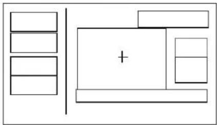
natural_image
Simple line drawing of a room layout with furniture and a central plus sign (no text or symbols)③ Setting the user marker color
- In the "COL" column, select a desired display color from 7 colors. The 12 types of user markers can be color-coded to identify them if two or more user markers are used.
- Settings: White, yellow, cyan, green, magenta, red and blue
- Default setting is white.
④ Setting the user marker display ON/OFF
- In the "SW" column, the display can be turned on and off.
- Default setting is ON.
⑤ User marker coordinates
- In the “DATA (X Y)” column, the coordinates for S: START POINT and E: END POINT of the currently set user markers are displayed.
- Move the cursor to the X/Y data. Using the UP/DOWN/ENT/ESC new user markers can be drawn or already registered user markers can be modified.
- The setting can be made in 1-pixel increments. The top left of the effective screen serves as the reference point (0001, 0001) of the coordinates. From this point, the coordinates can be adjusted in the pixel range of 3840 × 2160 .
- Default setting is (1920,1080).
- Resetting the data
With the “DATA (X Y)” in ⑤ blinking, rotating the mouse wheel upwards a few times will return it to the initial value.
● Coordinate reference point
This 3840 x 2160, Full-HD panel has a pixel reference point (0001, 0001) at the top left of the screen. The pixel at the bottom right of the screen is preset as the coordinates (3840, 2160).

flowchart
graph TD
    A["(0001,0001)"] --> B["X axis"]
    C["(0001,2160)"] --> D["Y axis"]
    B --> E["(3840,0001)"]
    D --> F["(3840,2160)"]
●Marker lines and coordinate values
There are 4 line widths for the user markers. However, the coordinate for the start point and that for the end point are different by 3 pixel.

Accordingly, in drawing a horizontal line, the Y-direction address has a coordinate value with 3pixel added, as shown below.

When a vertical line is drawn, the X-axis address has a coordinate value with 3 pixel added, as shown below.


flowchart
graph TD
    A["How to preset new user markers"] --> B["① Setting the marker display ON/OFF"]
    B --> C["<MARKER> MARKER(16:9,1.90:1) SAFETY"]
    C --> D["SET USER MARKER to ON."]
    D --> E["Move the cursor"]
    E --> F["② Execute the drawing mode"]
    F --> G["<MARKER> MARKER(16:9) SAFETY"]
    G --> H["Press ENT."]
    H --> I["③ Setting the individual markers"]
    I --> J["<SETTING OF USER MARKER> PAGE1"]
    J --> K["No. SW COL DATA(X Y)"]
    K --> L["MK1 ON S: ----"]
    L --> M["MK2 OFF S: ----"]
    M --> N["MK3 OFF S: ----"]
    N --> O["MK4 OFF S: ----"]
    O --> P["MK5 OFF S: ----"]
    P --> Q["MK6 OFF S: ----"]
    Q --> R["▼(NEXT PAGE)"]
    R --> S["④ Going to the drawing menu"]
    S --> T["<SETTING OF USER MARKER> PAGE1"]
    T --> U["No. SW COL DATA(X Y)"]
    U --> V["MK1 ON S: ----"]
    V --> W["MK2 OFF S: ----"]
    W --> X["MK3 OFF S: ----"]
    X --> Y["MK4 OFF S: ----"]
    Y --> Z["MK5 OFF S: ----"]
    Z --> AA["MK6 OFF S: ----"]
    AA --> AB["▼(NEXT PAGE)"]
    AB --> AC["⑤ This menu screen in step 3 reappears and the settings are displayed with their x-y coordinates."]

    subgraph Step 1
        D --> D1["START POINT(X : 2048 , Y : 1080) END POINT (X : 2048 , Y : 1080)"]
        E --> E1["With nothing registered, the initial X-Y coordinate is displayed, and the start-point X-Y coordinate starts blinking."]
        F --> F1["With nothing registered, the cursor is displayed at the default center."]
        G --> G1["The shifted X-Y coordinate is displayed."]
        H --> H1["Move the cursor to the start point."]
        I --> I1["The end-point X-Y coordinate starts blinking."]
        J --> J1["Set the color and ON/OFF display for individual markers."]
        K --> K1["Set the color and ON/OFF display for individual markers."]
        L --> L1["Start point X: 0700, Y: 0540"]
        M --> M1["Start point X: 0700, Y: 0540"]
        N --> N1["Start point X: 0700, Y: 0540"]
        O --> O1["Start point X: 0700, Y: 0540"]
        P --> P1["Start point X: 0700, Y: 0540"]
        Q --> Q1["Start point X: 0700, Y: 0540"]
        R --> R1["Start point X: 0700, Y: 0540"]
        S --> S1["Start point X: 0700, Y: 0540"]
        T --> T1["Start point X: 0700, Y: 0540"]
        U --> U1["Start point X: 0700, Y: 0540"]
        V --> V1["Start point X: 0700, Y: 0540"]
        W --> W1["Start point X: 0700, Y: 0540"]
        X --> X1["Start point X: 0700, Y: 0540"]
        Y --> Y1["Start point X: 0700, Y: 0540"]
        Z --> Z1["Start point X: 0700, Y: 0540"]
        AA --> AA1["Start point X: 0700, Y: 0540"]
        AB --> AB1["Start point X: 0700, Y: 0540"]
        AC --> AC1["Start point X: 0700, Y: 0540"]
        AD --> AD1["Start point X: 0700, Y: 0540"]
        AE --> AE1["Start point X: 0700, Y: 0540"]
        AF --> AF1["Start point X: 0700, Y: 0540"]
        AG --> AG1["Start point X: 0700, Y: 0540"]
        AH --> AH1["Start point X: 0700, Y: 0540"]
        AI --> AI1["Start point X: 0700, Y: 0540"]
        AJ --> AJ1["Start point X: 0700, Y: 0540"]
        AK --> AK1["Start point X: 0700, Y: 0540"]
        AL --> AL1["Start point X: 0700, Y: 0540"]
        AM --> AM1["Start point X: 0700, Y: 0540"]
        AN --> AN1["Start point X: 0700, Y: 0540"]
        AO --> AO1["Start point X: 0700, Y: 0540"]
        AP --> AP1["Start point X: 0700, Y: 0540"]
        AQ --> AQ1["Start point X: 0700, Y: 0540"]
        AR --> AR1["Start point X: 0700, Y: 0540"]
        AS --> AS1["Start point X: 0700, Y: 0540"]
        AT --> AT1["Start point X: 0700, Y: 0540"]
        AU --> AU1["Start point X: 0700, Y: 0540"]
        AV --> AV1["Start point X: 0700, Y: 0540"]
        AW --> AW1["Start point X: 0700, Y: 0540"]
        AX --> AX1["Start point X: 0700, Y: 0540"]
        AY --> AY1["Start point X: 2226"]
        AZ --> AZ1["Take the procedure to set a new start point."]
        BA --> BB["ESC"]
        BC --> BC
        BD --> BD
        BE --> BE
        BF --> BF
        BG --> BG
        BH --> BH
        BI --> BI
        BJ --> BJ
        BK --> BK
        BL --> BL
        BM --> BM
        BN --> BN
        BO --> BO
        BP --> BP
        BPB --> BP
        BPB2 --> BP
        BPB2B --> BP
        BPB2B2 --> BP
        BPB2B2B --> BP
    end
    subgraph Step 3
        B --> BAY["This menu screen in step 3 reappears and the settings are displayed with their x-y coordinates."]
    end

    subgraph Step 4
        D --> DXY["X axis"]
        E --> DXY
        F --> DXY
        G --> DXY
        H --> DXY
        I --> DXY
        J --> DXY
        K --> DXY
        L --> DXY
        M --> DXY
        N --> DXY
        O --> DXY
        P --> DXY
        Q --> DXY
        R --> DXY
        S --> DXY
        T --> DXY
        U --> DXY
        V --> DXY
        W --> DXY
        X --> DXY
        Y --> DXY
        Z --> DXY
    end

    subgraph Step 5
        DXY & EXY & FXY & GXY & HXY & IXY & JXY & KXY & LXY & MXY & NXY & OXY & PXY & QXY & RXY & SXY & TXY & UXY & VXY & WXY & AX & BXY & BZ & BZ & BZ & BZ & BZ & BZ & BZ & BZ & BZ & BZ & BZ & BZ & BZ & BZ & BZ & BZ & BZ & BZ & BZ & BZ & BZ & BZ & BZ & BZ & BZ & BZ & BZ & BZ & BZ & BZ & BZ & BZ & BZ & BZ &
    end
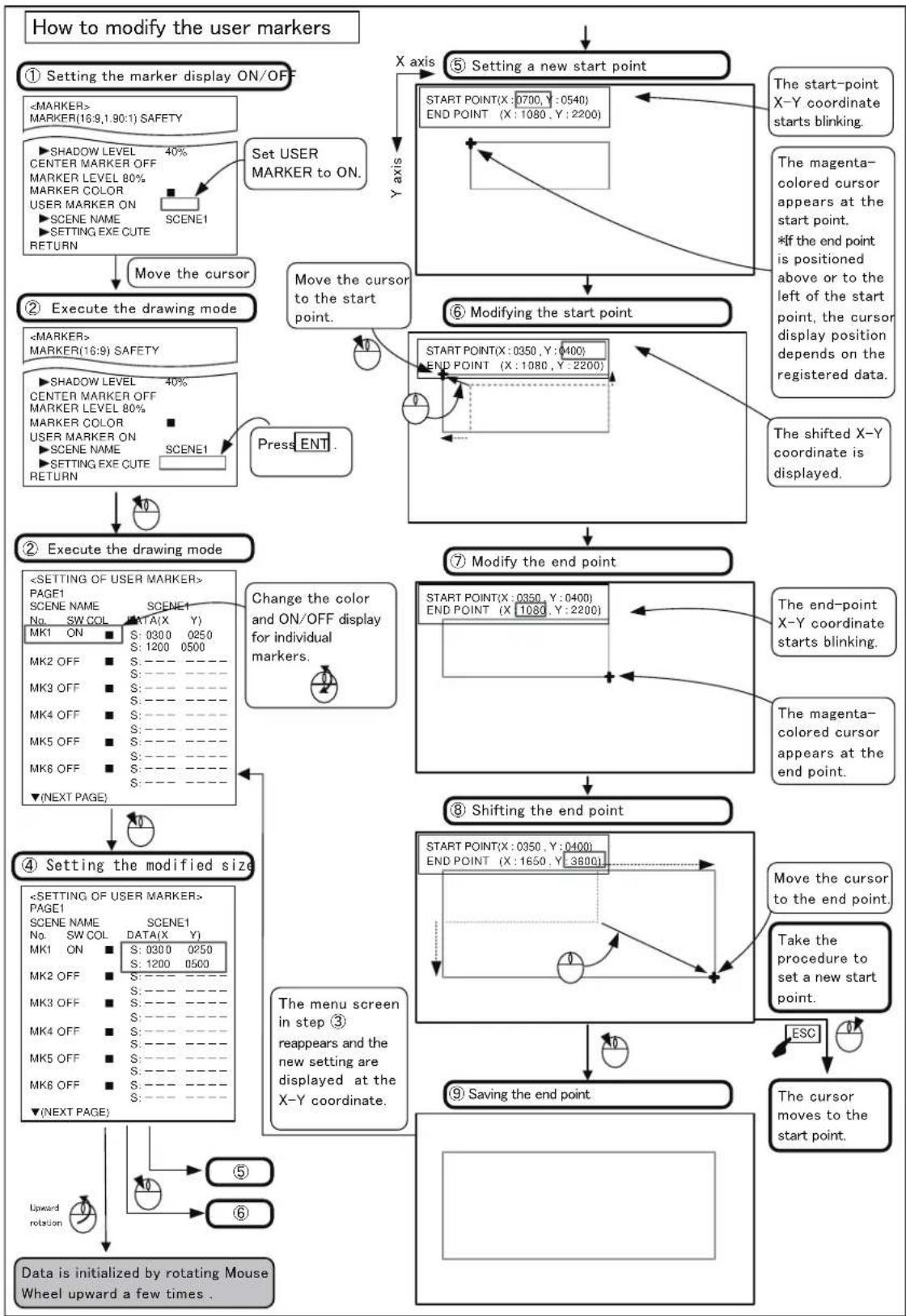
flowchart
graph TD
    A["How to modify the user markers"] --> B["① Setting the marker display ON/OFF"]
    B --> C["<MARKER> MARKER(16:9,1:30:1) SAFETY"]
    C --> D["SET USER MARKER TO ON."]
    D --> E["Move the cursor"]
    E --> F["② Execute the drawing mode"]
    F --> G["<MARKER> MARKER(16:9) SAFETY"]
    G --> H["SHADOW LEVEL 40% CENTER MARKER OFF MARKER LEVEL 80% MARKER COLOR USER MARKER ON SCENE NAME SETTING EXE CUTE RETURN SCENE1"]
    H --> I["Press ENT."]
    I --> J["③ Execute the drawing mode"]
    J --> K["<SETTING OF USER MARKER> PAGE1 SCENE NAME SCENE1 NO. SW COL DATA(X Y) MK1 ON S: 0300 0250 S: 1200 0500 MK2 OFF S: ---- ---- MK3 OFF S: ---- ---- MK4 OFF S: ---- ---- MK5 OFF S: ---- ---- MK6 OFF S: ---- ---- ▼(NEXT PAGE)"]
    K --> L["④ Setting the modified size"]
    L --> M["The menu screen in step ③ reappears and the new setting are displayed at the X-Y coordinate."]
    M --> N["Data is initialized by rotating Mouse Wheel upward a few times."]
    N --> O["↑ Upward rotation"]
    O --> P["⑤ Setting a new start point"]
    P --> Q["START POINT(X: 0700, Y: 0540) END POINT (X: 1080, Y: 2200)"]
    Q --> R["The start-point X-Y coordinate starts blinking."]
    R --> S["The magenta-colored cursor appears at the start point. *If the end point is positioned above or to the left of the start point, the cursor display position depends on the registered data."]
    S --> T["⑥ Modifying the start point"]
    T --> U["START POINT(X: 0350, Y: 0400) END POINT (X: 1080, Y: 2200)"]
    U --> V["The shifted X-Y coordinate is displayed."]
    V --> W["⑦ Modify the end point"]
    W --> X["START POINT(X: 0350, Y: 0400) END POINT (X: 1080, Y: 2200)"]
    X --> Y["The end-point X-Y coordinate starts blinking."]
    Y --> Z["The magenta-colored cursor appears at the end point."]
    Z --> AA["⑧ Shifting the end point"]
    AA --> AB["START POINT(X: 0350, Y: 0400) END POINT (X: 1650, Y: 3600)"]
    AB --> AC["Move the cursor to the end point."]
    AC --> AD["Take the procedure to set a new start point."]
    AD --> AE["ESC"]
    AE --> AF["The cursor moves to the start point."]
    AF --> AG["⑨ Saving the end point"]
4-8. Description of MENU-UTILITY Functions

① Setting the CONT VR ASSIGN
- The "CONT" volume at the front can be operated for the purpose of backlight adjustment. However, when EOTF setting is HLG or PQ, backlight adjustment is not possible.
- CONT: Operates for the purpose of CONTRAST adjustment
- BL: Operates for the purpose of backlight adjustment. This setting is reflected on the PRESET value.
- Default setting is CONT.
② Setting the CONTRAST RANGE
• NORMAL : When the CONTRAST volume is set to the maximum intensity level, images with low intensity can be increased to 1.2 times higher. In addition, sections where overflow occurs within high-intensity images, a clip is applied.
- WIDE : The contrast level can be increased to two times.
*High level video may saturate.
- Default setting is NORMAL.
③ Setting the TALLY
- Set any of the following display modes of the tally lamps located at the top of the front of the monitor.
- R/G : R is on the left side and G on the right side, when facing the screen.

[R-TALLY ON] [G-TALLY ON]
- G/R : G is on the left side and R on the right side, when facing the screen.

[G-TALLY ON] [R-TALLY ON]
- R+G : The entire tally is displayed. The lamp is displayed in amber when both the R-TALLY and G-TALLY are set at ON. Both R- and G-TALLY at ON.
![R ← [ R-TALLY ON ] G ←[G-TALLY ON ] AMBER ←[Both R and G-TALLY at ON ]](/content/2026/05/979870/images/a0dc5cad05a962555be022e94d44cf39e9cfae71f7948bc40c8b13ab1c13c36d.jpg)
• R/G ALL : Displays the entire TALLY only when it is solely set to ON. If both R-TALLY and G-TALLY are set to ON, they will be displayed on the left and right sides.
![R G R G [ R-TALLY ON ] [G-TALLY ON ] [Both R and G-TALLY at ON ]](/content/2026/05/979870/images/89bcc0b52db5aa5e5e3afa7288d7295b99cd8828f1d732db4b991f08d2dbfa86.jpg)
- G/R ALL : Displays the entire TALLY only when it is solely set to ON. If both R-TALLY and G-TALLY are set to ON, they will be displayed on the left and right sides.
![R ←[R·TALLY ON] G ←[G·TALLY ON] G R ←[Both R and G·TALLY at ON]](/content/2026/05/979870/images/5cd0f911b1879bbe5a56d97ce92cbb7c11401ece467515515c70dfc559ce8af9.jpg)
- Default setting is R/G.
④ Setting the FORMAT DISPLAY
• Used to set whether the channel and signal format are displayed or not.
- 3SEC ON : Three seconds indication
- CONT ON : Continuous indication
· OFF : Hidden
- Default setting is 3SEC.
⑤ FRONT LIGHT operation mode
- The mode when the operation panel is illuminated is set.
OFF : Always off
ON : Always on
AUTO : Light on when the front panel switch or dial is operated.
Light off when no operation is performed for 20 seconds.
- Default setting is AUTO.
⑥ FRONT LIGHT illumination setting
- The brightness to illuminate the operation panel is set.
LOW : Dark
HIGH : Bright
- Default setting is LOW.
⑦ FRONT LED (OVER RANGE) illumination setting
- Illumination ON/OFF of OVER RANGE LED on the front is set.
OFF : Not illuminate
O.RANGE : Illuminate
- Default setting is OFF.
⑧ Setting the SYSTEM LOCK
• The data protection setting starts.
Shifting to LOCK ALL/PRESET
- By selecting EXECUTE, LOCK ALL/RESET setting starts, and protection of various data, password setting, and protection of preset data become possible. Refer to ⑨ and ⑩ for details.
⑨ CONFIG and PASSWORD settings
CONFIG contents
- UNLOCK : The lock is released and all data can be changed.
- PRESET LOCK: The PRESET MENU setting of item 5 is locked.
- ALL LOCK : In addition to the PRESET MENU lock, the MENU setting is also locked.
* When "POWER ON CONFIG" is set to "ON", setting the LOCK MODE is not possible.
* FUNCTION switch assignments, functions related to MENU setting and PRESET MENU setting are locked.
PASSWORD setting
. Selecting ENTER PASSWORD and setting as shown in the right figure enables the password setting.

flowchart
graph TD
    A["4K/2K/MULTI"] --> B["VIDEO"]
    A --> C["AUDIO"]
    A --> D["TC/WFM/VSC"]
    A --> E["MARKER"]
    A --> F["UTILITY"]
    A --> G["FUNC.SW"]
    A --> H["P.REMOTE"]
    A --> I["UMD/IMD"]
    A --> J["C.CAPTION"]
    A --> K["USB"]
    A --> L["NETWORK"]
    A --> M["RESET"]
    A --> N["INFO"]
    A --> O["EXIT"]
    B --> P["<UTILITY> CONT VR ASSIGN CONT"]
    C --> Q["CONTRAST RANGE NORMAL"]
    D --> R["TALLY R/G"]
    E --> S["INPUT LOCK OFF"]
    F --> T["FORMAT DISPLAY 3SEG"]
    G --> U["FRONT LIGHT AUTO"]
    H --> V["► DIMMER LOW"]
    I --> W["SYSTEM LOCK EXECUTE"]
    J --> X["RETURN EXECUTE"]
    K --> Y["RETURN EXECUTE"]
    L --> Z["RETURN EXECUTE"]
    M --> AA["RETURN EXECUTE"]
    N --> AB["RETURN EXECUTE"]
    O --> AC["RETURN EXECUTE"]

    subgraph Select "ENTER PASSWORD"
        B
        P
        Q
        R
        S
        T
        U
        V
        W
        X
        Y
        Z
        AA
        AB
        AC
        AD
        AE
        AF
        AG
        AH
        AI
        AJ
        AK
        AL
        AM
        AN
        AO
        AP
        AQ
        AR
        AS
        AT
        AU
        AV
        AW
        AX
        AY
        AZ
        BA
        BB
        BC
        BD
        BE
        BF
        BG
        BH
        BI
        BJ
        BK
        BL
        BM
        BN
        BO
        BP
        BP1
        BP2
        BP3
        BP4
        BP5
        BP6
        BP7
        BP8
        BP9
        BP10
        BP11
        BP12
        BP13
        BP14
        BP15
        BP16
        BP17
        BP18
        BP19
        BP20
        BP21
        BP22
        BP23
        BP24
        BP25
        BP26
        BP27
        BP28
        BP29
        BP30
        BP31
        BP32
        BP33
        BP34
        BP35
        BP36
        BP37
        BP38
        BP39
        BP40
        BP41
        BP42
        BP43
        BP44
        BP45
        BP46
        BP47
        BP48
        BP49
        BP50
        BP51
        BP52
        BP53
        BP54
        BP55
        BP56
        BP57
        BP58
        BP59
        BP60
        BP61
        BP62
        BP63
        BP64
        BP65
        BP66
        BP67
        BP68
        BP69
        BP70
        BP71
        BP72
        BP73
        BP74
        BP75
        BP76
        BP77
        BP78
        BP79
    end

    subgraph Set password with 4 digits.
            B --> P["LOCK ALL/PRESET"]
            P --> Q["STATUS: UNLOCK"]
            Q --> R["ENTER PASSWORD: ABCDEFGHIJKLM"]
            R --> S["NO PCRSTUVWXYZ D123456789"]
            S --> T["PASSWORD ...."]
            T --> U["LOCK ALL/PRESET"]
            U --> V["STATUS: UNLOCK"]
            V --> R2["ENTER PASSWORD: ABCDEFGHIJKLM"]
            R2 --> S2["NO PCRSTUVWXYZ D123456789"]
            S2 --> T3["PASSWORD ...... UNLOCK"]
            T3 --> U3["A B C D UNLOCK"]
            U3 --> V4["LOCK ALL/PRESET"]
            V4 --> W["STATUS: UNLOCK"]
            W --> X["ENTER PASSWORD: ABCDEFGHIJKLM"]
            X --> Y["NO PCRSTUVWXYZ D123456789"]
            Y --> Z["PASSWORD ...... UNLOCK"]
            Z --> U4["A B C D UNLOCK"]
            U4 --> V5["Set LOCK mode."]
            V5 --> W4["Set LOCK mode."]
            W4 --> X4["Set LOCK mode setting complete."]
    end

    subgraph Four-digit password is displayed hear.
            V4 --> W4A["A four-digit password is displayed hear."]
    end

    style Select "ENTER PASSWORD" fill:#f9f,stroke:#333,stroke-width:2px;
    style Set password with 4 digits fill:#ccf,stroke:#333,stroke-width:2px;
    style Four-digit password is displayed hear fill:#cfc,stroke:#333,stroke-width:2px;
    style Lock mode fill:#fcc,stroke:#333,stroke-width:2px;
    style Lock mode setting complete fill:#ffc,stroke:#333,stroke-width:2px;
⑩ Setting the POWER ON CONFIG
- "POWER ON CONFIG"
ON: When the power is turned on, MENU and PRESET MENU settings memorized during "SAVE CONFIG" execution are read and started up.
In addition, when MENU and PRESET MENU contents are changed after execution of "SAVE CONFIG" the condition at power-on does not get affected.
OFF: When the power is turned on, MENU and PRESET MENU settings before the power was turned off are read and started up.
- "SAVE CONFIG"
The MENU and PRESET MENU set items are memorized. When the power is turned on with "POWER ON CONFIG: ON" condition, the memorized contents are called and started up. However, the following items are not memorized.
* Items which are not memorized in "POWER ON CONFIG"
- POWER ON ONFIG memory method

flowchart
graph TD
    A["4K2K/MULTI"] --> B["VIDEO"]
    B --> C["AUDIO"]
    C --> D["TC/WFM/VSC"]
    D --> E["MARKER"]
    E --> F["UTILITY"]
    F --> G["FUNC.SW"]
    G --> H["P.REMOTE"]
    H --> I["UMD/IMD"]
    I --> J["C.CAPTION"]
    J --> K["USB"]
    K --> L["NETWORK"]
    L --> M["RESET"]
    M --> N["INFO"]
    N --> O["EXIT"]
    P["<UTILITY>"] --> Q["CONT VR ASSIGN CONT"]
    Q --> R["CONTRAST RANGE NORMAL"]
    R --> S["TALLY R/G"]
    S --> T["INPUT LOCK OFF"]
    T --> U["FORMAT DISPLAY 3SEC"]
    U --> V["FRONT LIGHT AUTO"]
    V --> W["► DIMMER LOW"]
    W --> X["SYSTEM LOCK EXECUTE"]
    X --> Y["RETURN"]

    Z["<LOCK ALL/PRESET>"] --> AA["CONFIG UNLOCK"]
    AA --> AB["ENTER PASSWORD"]
    AB --> AC["POWER ON CONFIG OFF"]
    AC --> AD["SAVE CONFIG EXECUTE"]
    AD --> AE["RETURN"]

    AF["<LOCK ALL/PRESET>"] --> AG["CONFIG UNLOCK"]
    AG --> AH["ENTER PASSWORD"]
    AH --> AI["POWER ON CONFIG ON"]
    AI --> AJ["SAVE CONFIG EXECUTE"]
    AJ --> AK["RETURN"]

    AL["Execute the currently set state."]
    AM["Set to ON"] --> AN
4-9. Description of MENU-FUNC.SW Functions

① Setting the function assignment of the F1 switch
- The function assignment is selectable from the table shown below. Then the assigned function is controlled by pressing the F1 switch on the front panel.
- Default setting is WFM ON.
② Setting the function assignment of the F2 switch
- The function assignment is selectable in the same way as described above.
- Default setting is TC ON.
③ Setting the function assignment of the F3 switch
- The function assignment is selectable in the same way as described above.
- Default setting is MIX TEST.
④ Setting the function assignment of the F4 switch
- The function assignment is selectable in the same way as described above.
- Default setting is VSC ON.
Function switches allocation table
| Allocation name | Function | Switched | content | Related |
| CHROMA UP FILE | Increase of chroma level | ON OFF | MENU-VIDEO· CROMA GAIN UP | |
| Switching of preset file | D65 D93 FILE1 ~ 8 | PRESET-SELECT FILE | ||
| SCAN | Switching of scan mode for 2K to 4K up-conversion | NORMAL NATIVE | MENU-VIDEO-SCAN | MODE |
| REAL SCAN | Indication of no resizing 2K signal | ON OFF | MENU-VIDEO-REAL SCAN | |
| MRK SEL | Marker type setting | SAFETY FRM+SAFE CROSS5 CROSS10C.CROSS ASPECT ASP+SAF | MENU-MARKER-MARKER | |
| C.MRK ON | Center marker ON/OFF | ON(TypeA or TypeB) OFF | MENU-MARKER-CENTER MARKER | |
| UMRK ON | User marker ON/OFF | ON OFF | MENU-MARKER-USER MARKER | |
| UMRK SEL | User marker selection | SCENE1 ~ SCENE10 OFF | MENU-MARKER-SCENE NAME | |
| DELAY | DELAY selection | H.DELAY V.DELAY H/V.DELAY OFF | Allocation to function switches only | |
| AUD CH | Switching of embedded audio channel | CH1/2→CH3/4→····..→CH13/14→CH15/16→DMIX | MENU-AUDIO-LINE SP/CH | |
| BL DIM | Increase of backlight intensity level | 1→2→3→4→5→6→···· 29→30 | PRESET-BACKLIGHT DIMMIX | |
| MIX TEST | MIX TEST SIGNAL function ON/OFF | ON OFF | 4K/2K MULTI-MIX TEST SIGNAL | |
| WFM ON | Indication of WFM | ON OFF | MENU-TC/WFM/VSC-WFM DISPLAY | |
| TC ON | Indication of TIME RECORD | ON(VITC or LTC) OFF | MENU-TC/WFM/VSC-TC SELECTVSC | |
| VSC ON | Indication of VECTOR | ON OFF | MENU-TC/WFM/VSC-VECTOR SCOPE | |
| WB | Adjustment of RGB balance, etc. | Indication of preset data change menu *1 | PRESET· CHANGE FILE | |
| VIEW MODE | Switching of VIEW MODE | 4K MODE→2K MODE→MULTI MODE | MENU-4K/2K MULTI-VIEW MODE | |
| VIEW 4K | Switching of VIEW MODE to VIEW 4K | From other mode to VIEW 4K | MENU-4K/2K MULTI-VIEW MODE | |
| VIEW 2K | Switching of VIEW MODE to VIEW 2K | From other mode to VIEW 2K | MENU-4K/2K MULTI-VIEW MODE | |
| VIEW MULTI | Switching of VIEW MODE to VIEW MULTI | From other mode to VIEW MULTI | MENU-4K/2K MULTI-VIEW MODE | |
| CC ON | Closed caption | ON OFF | MENU-C.CAPTION-CLOSED CAPTION | |
| LIGHT_ON | Control of FRONT LIGHT (operation panel light) | ON OFF | MENU-UTILITY-FRONT LIGHT |
*1 Does not operate when ALL LOCK is selected.
4-10. Description of MENU-P.REMOTE Functions
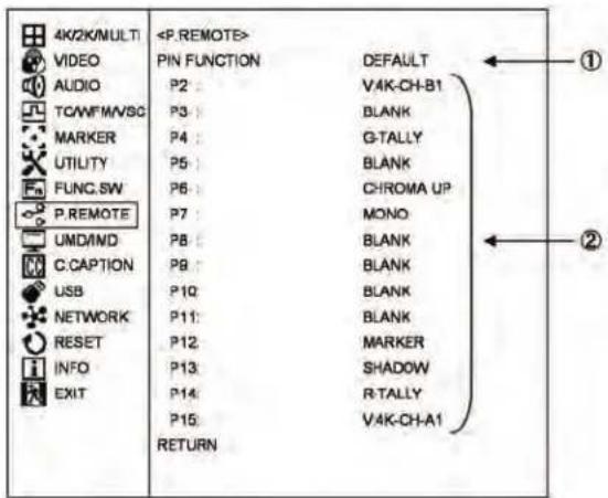
① Setting the functions of the parallel remote pins
- Select the pre-assigned pin functions of the parallel remote control or the individual user-set functions.
* By default, the pre-assigned pin functions are displayed beneath.
* Refer to "Pin function in default" section in "Dtat 2 Parallel remote pin function."
② Setting the user pin function
- When "USER" is selected in ①, set the individual pin functions. The following functions are available for setting.
For details, refer to "Pin function in default" section and "Functions added by user setting" section in "Data 2 Parallel remote pin function."
* Refer to "Data 2 Parallel remote pin function" for details.
• V:4K-CH-A1 : when input is changed to CH-A1 in 4k mode
- V-4K-CH-B1 : when input is changed to CH-B1 in 4k mode
• V:4K-CH-HDMI : when input is changed to HDMI in 4k mode
• V:2K-CH-A1 : when input is changed to CH-A1 in 2k mode
• V:2K-CH-B1 : when input is changed to CH-B1 in 2k mode
• V:2K-HDMI : when input is changed to HDMI in 2k mode
• MONO : selection of MONO
- SHADOW : shadow ON at the level set in "MENU-MARKER-SHADOW"
- SHADOW0 : shadow ON at shadow level 0% (Black)
- SHADOW20 : shadow ON at shadow level 20%
- SHADOW40 : shadow ON at shadow level 40%
- SHADOW60 : shadow ON at shadow level 60%
* "SHADOW0", "SHADOW20", "SHADOW40" and "SHADOW60" functions
- Select two or more SHADOW settings at once, and "SHADOW0" (Black) is given priority.
- When any of these functions is turned ON, the "MENU-MARKER"-adjusted shadow level is forced to go back to the level remotely preset.
* The functions of the following pins, which are fixed, cannot be changed.
• Pin 1 (P1): GND
4-11. Description of MENU-UMD/IMD Functions
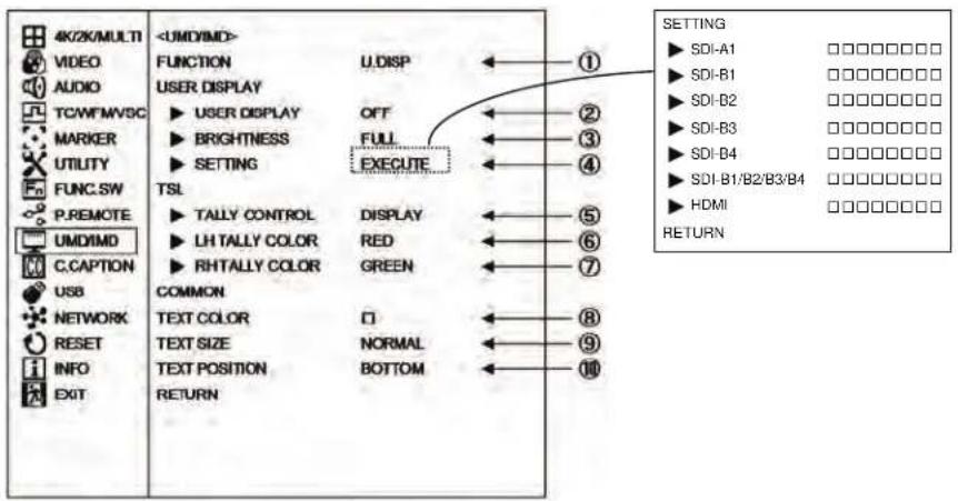
① Setting the TSL/USER DISPLAY function switching
- Selects whether the UMD/IMD display is performed by TSL or DISPLAY.
- TSL: TSL is enabled
• U.DISP.: USER DISPLAY is enabled
- Default setting is U.DISP.
② Setting the USER DISPLAY ON/OFF
- Selects whether the USER DISPLAY characters set in section ④ are displayed on the screen or not..
• ON: Displays on the screen
• OFF: Does not display
Also in the MULTI display, characters corresponding to inputs set in ④ are displayed. The following is an example of 2 MULTI.

- Default setting is OFF.
③ Setting the USER DISPLAY character brightness
- Sets the brightness of characters that are displayed on the screen.
· FULL: 100% brightness
• 1/2: 50% brightness
• 1/7: 30% brightness
- Default setting is FULL.
④ Setting the USER DISPLAY character content
- When "EXECUTE" is performed, the following MENU is displayed, then you can set the character contents.
| SETTING | |
| SDI-A1 | □□□□□□□□ |
| SDI-B1 | □□□□□□□□ |
| SDI-B2 | □□□□□□□□ |
| SDI-B3 | □□□□□□□□ |
| SDI-B4 | □□□□□□□□ |
| SDI-B1/B2/B3/B4 | □□□□□□□□ |
| HDMI | □□□□□□□□ |
| RETURN | |
• Here you can set 8 characters to be displayed on the screen when switching each input channel.
- Character types
ABCDEFGHIJKLMNOPQRSTUVWXYZ0123456789-() [blank]
⑤ Setting the TSL TALLY light-up method
- Sets whether to light up the TALLY set on the top of monitor or display it on the screen.
• DISPLAY: Displays on the screen - LED: LED lights up.
- Default setting is DISPLAY


⑥ Setting the TSL TALLY (left side) color
- Slects the display color for the TALLY (left side) from three colors: "RED/GREEN/AMBER".
- Default setting is RED
⑦ Setting the TSL TALLY (right side) color
- Selects the display color for the TALLY (right side) from three colors: "RED/GREEN/AMBER".
- Default setting is GREEN
⑧ Setting the Display character color (common setting item)
- Selects the character color from seven colors: "WHITE/YELLOW/CYAN/GREEN/MAGENT/RED/BLUE".
- Default setting is WHITE
⑨ Setting the Display character size (common setting item)
- Selects the character size from two types: "NORMAL/SMALL".
• NORMAL: Character size, large
- SMALL: Character size, small
- Default setting is NORMAL
⑩ Setting the Display character position (common setting item)
- Selects the character position from two types:
• BOTTOM: Displays on the bottom of screen
• TOP: Displays on the top of screen
UMD/IMD IndicationTable
TEXT SIZE : NORMAL TEXT POSITION : BOTTOM

natural_image
Simple diagram with a circle centered on four surrounding circles, labeled 'ABCDEFGH' at the bottom (no other text or symbols)natural_image
Simple diagram with a circle centered on four surrounding circles, labeled 'ABCDEFGH' at the bottom (no text or symbols within the diagram itself)TEXT SIZE : SMALL TEXT POSITION : TOP
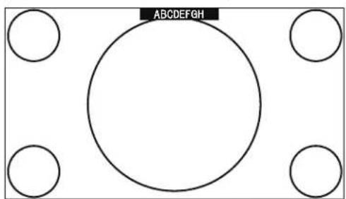
natural_image
Simple diagram with a circle centered on four surrounding circles, no text or symbols present.4-12. Description of MENU-C.CAPTION Functions
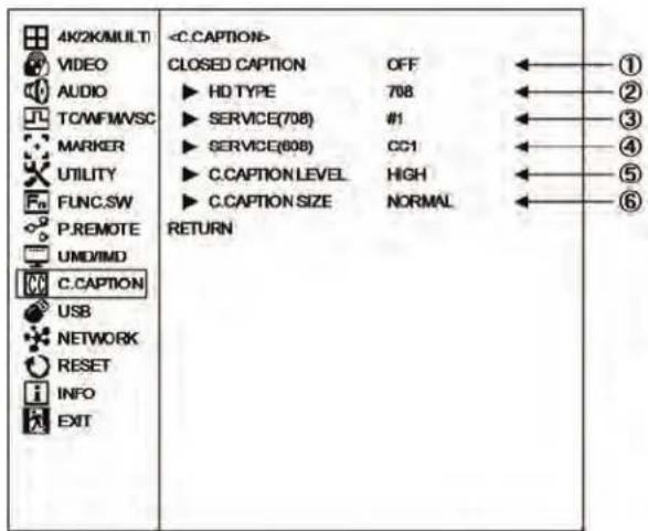
① Setting of closed caption ON/OFF
• The closed caption ON/OFF is set.
* When the menu is displayed, the closed caption is not displayed.
- Default setting is OFF.
② Setting of the HD-SDI signal closed caption type
· 708 : It is selected when displaying 708 of the HD-SDI signal.
- 608/708 : It is selected when displaying 608/708 of the HD-SDI signal.
※ 708 is the closed caption signal of the EIA/CEA-708 standard.
608/708 is the closed caption signal of the EIA/CEA-608 standard which is transmitted with the EIA/CEA-708 standard.
Default setting is 708.
③ HD TYPE display subtitle setting
- Select from SERVICE #1 through #6.
- Default setting is #1.
④ SD TYPE display subtitle setting
. Select from CC1 through CC4 and TEXT1 through TEXT4
- Default is CC1.
⑤ Brightness setting of closed caption
- The closed caption brightness is set. - Select from HIGH and LOW.
- Default setting is HIGH.
⑥ Display size setting of closed caption
. Select the character size from NORMAL or LARGE.
- Default setting is NORMAL.
4-13. Description of MENU-USB MEMORY Functions

Writing from monitor to USB memory
① Setting the date of a file to be written on USB memory
• Used to set the editing date of a file to be written on a USB memory. Enter a date when you are going to write on the USB memory. When reviewing files on a computer, the date entered here will be displayed as the date of the file.
- Enter "Y (year)/M (month)/D (day)" in this order.
- If no date is entered, the file will be edited as of the date appearing currently in the menu.
② Setting the time of a file to be written on USB memory
• Used to set the editing time of a file in a way similar to Item ①.
- Enter “H (hour) : M (minute)” in this order. If no time is entered, the file will be edited as of the time appearing currently in the menu.
② -⑥ Writing to USB memory
- To write all the setting data from the monitor to a USB memory, select "EXECUTE" and press the ENT. For writing details, refer to "How to write from monitor to USB memory".
- File format for writing to USB memory Files to be written from the monitor to a USB memory are created in the following 3 text files.
File structure
MENUSW.TXT
- File to save the menu (USER MARKER and PRESET MENU not included) status and the switch settings.
- Data capacity: Approx. 6 Kbyte
- Since this is a model-specific file, you cannot download the data that was stored with a different model or vise versa.
UMARK01.TXT (for SCENE1) UMARK02.TXT (for SCENE2)
UMARK10.TXT (for SCENE10)
- File to save various setting data of the user markers that are preset in
MENU-MARKER.
- Data capacity: Approx. 2 Kbyte (per scene)
PRECTL.TXT (for PRESETcontrol)
PRED65.TXT (for D65)
PRED93.TXT (for D93)
PREACES.TXT (for ACES)
PREDCI.TXT (for DCI)
PREFILE1.TXT (for FILE1)
PREFILE2.TXT (for FILE2)
PREFILE3.TXT (for FILE3)
PREFILE4.TXT (for FILE4)
PREFILE5.TXT (for FILE5)
PREFILE6.TXT (for FILE6)
PREFILE7.TXT (for FILE7)
PREFILE8.TXT (for FILE8)
- File to save the PRESET menu settings as well as all the D65, D93 and FILE1 thru -8 data.
The password lock and the password itself are not saved, however. - Data capacity: Approx. 1 Kbyte (per file)
The PRESET data of other models cannot be downloaded.
◆Precautions on writing
- With a USB connected to the monitor, do not turn ON/OFF the monitor or disconnect the inserted USB memory while writing is going on, or else the USB memory may possibly be damaged. Be sure to disconnect the USB memory in accordance with the procedure described under "How to write from monitor to USB memory".
- Do not change the name of an automatically generated folder or a file, or else downloading to the monitor will be disabled. Do not modify the data in a file, or else the order of the data may be altered, disabling writing of the data.
- If there is a file already in the specified folder, the data of a new file will be overwritten on the existing file.
- High-security USB memories may not be recognized.
- There are some types of USB memory that can not be recognized, please use another USB memory if not recognized.
Downloading from USB memory to monitor
③—⑤ Selecting items to be downloaded
- Select the items of data to be downloaded from the USB memory to the monitor. Tick the check box.
- Contents of individual items a) □MENU&SW
- Tick this check box to download the setting status of all the menus (excluding USER MARKER MENU and PRESET MENU) and the switch setting status.
. The following files are dedicated to each model and loaded as model-specific files. "¥MENUSW.TXT"
* Since this is a model-specific file, you cannot download data that was stored with a different model.
b) □USER MARKER
- Check this box if you want to download the various settings (color, ON/OFF, XY coordinates) of "S01 (SCENE1) to S10 (SCENE10)" that were set in the MENU-MERKER -USER MARKER.
- The files for each scene of "UMARK01.TXT" to "UMERK10.TXT" will be downloaded.
* Since this is a model-specific file, you cannot download data that was stored with a different model.
c) □PRESET
- To download the items set on the PRESET MENU and all of the data of D65, D93, and FILE 1 \~ 8, tick this check box.
* If the data is locked with a password, you cannot check the box. Please enter the password and unlock it before downloading.
* Since this is a model-specific file, you cannot download data that was stored with a different model.
* It is possible to download the file from the same model. However, the color temperature data stored in the FILE is different for each device; therefore the same color temperature cannot be achieved even if you download the data. For this reason, the PRESET data should be downloaded for the purpose of data backup on each monitor.
⑦ Executing the downloading
- To download the data of the items selected under Item ④ from the USB memory to the monitor, press ENT under "EXECUTE."
Refer to "How to download from USB memory to monitor" for the details of writing.
- If the file specified under Item ④ does not exist in the specific folder of the USB memory, a warning message will appear.
◆Precautions on downloading
- With a USB memory connected to the monitor, do not turn ON/OFF the monitor or disconnect the inserted USB memory while downloading is going on, or else the USB memory may possibly be damaged. Be sure to disconnect the USB memory in accordance with the procedure described under "How to download from USB memory to monitor".
- Do not change the name of an automatically generated folder or a file, or else downloading to the monitor will be disabled. Do not modify the data in a file, or else the order of the data may be altered, disabling writing of the data.
- If a data in the monitor is locked with a password, "PRESET LOCK" or "ALL LOCK" will appear on the MENU as shown on the diagram below.
Enter the password to unlock the data first and then download the data. - It is possible in some cases that a high-security USB memory may not be recognized by the monitor.
◆Error messages during writing or downloading
ERROR-1 A file system error is detected
ERROR-2 USB memory is broken.
ERROR-3 USB memory is not connected
ERROR-4 File is not found
ERROR-4\~ Various errors on access
How to write from monitor to USB memory

flowchart
graph TD
A["How to write from monitor to USB memory"] --> B["<USB> SETTING DATE&TIME ▶ DATE(Y/M/D) 18/04/10<br>CONFIG ▶ MENU&SW ▶ USER MARKER ▶ PRESET<br>SAVE CONFIG EXECUTE LOAD CONFIG EXECUTE UP DATE ▶ MAIN MPU ▶ SUB MPU ▶ FPGA1 ▶ FPGA2 ▶ FPGA3 ▶ UP DATE EXECUTE RETURN"]
B --> C["Enter the data and time of a file to be written on a USB memory.<br>*If no data and time is entered hear, the already entered setting will be upheld.<br>Tick the check box (□) for items to write from the monitor to a USB memory."]
C --> D["Precaution<br>• Do not draw out the inserted USB memory until the writing has been completed. If drawn out during access, the device may get damaged.<br>• Use USB memory formatted in FAT32.<br>• The monitor cannot use USB memory with the security software."]
D --> E["Insert a USB memory into the USB port at the monitor front."]
E --> F["<USB> SETTING DATE&TIME ▶ DATE(Y/M/D) 18/04/10<br>CONFIG ▶ MENU&SW ▶ USER MARKER ▶ PRESET<br>SAVE CONFIG EXECUTE LOAD CONFIG EXECUTE RETURN"]
F --> G["Move the cursor to "EXECUTE" and press the ENT."]
G --> H["By pressing the ESC switch at this point the device is disconnected and the USB memory can be drawn out."]
H --> I["In case of trouble"]
I --> J["The monitor is detecting to see if the USB memory is inserted."]
J --> K["In normal state"]
K --> L["The detection result is displayed hear. When the USB memory is recognized. "USB MEMORY" appears onscreen."]
L --> M["Select "YES" if download is OK here, and select "NO" to cancel."]
M --> N["If you select [NO"] here, the device is disconnected and can be extracted.]
N --> O["During write"]
O --> P["RETURN SAVEING... DO NOT REMOVE THE DEVICE"]
P --> Q["RETURN JOB COMPLETED! DEVICE CAN BE REMOVED EXIT [ESC"]]
Q --> R["Write complete"]
R --> S["Draw out the USB memory"]
How to download from USB memory to monitor

flowchart
graph TD
A["How to download from USB memory to monitor"] --> B["<<USB>> SETTING DATE&TIME\n▶ DATE(Y/M/D) 18/04/01\n▶ TIME(H:M) 09:30\nCONFIG\n▶ MENU&SW\n▶ USER MARKER\n▶ PRESET\nSAVE CONFIG EXECUTE\nLOAD CONFIG EXECUTE UP DATE\n▶ MAIN MPU\n▶ SUB MPU\n▶ FPGA1\n▶ FPGA2\n▶ FPGA3\n▶ UP DATE\nRETURN EXECUTE"]
B --> C["Insert a USB memory into the USB port at the monitor front."]
C --> D["<<USB>> SETTING DATE&TIME\n▶ DATE(Y/M/D) 18/04/01\n▶ TIME(H:M) 09:30\nCONFIG\n▶ MENU&SW\n▶ USER MARKER\n▶ PRESET\nSAVE CONFIG EXECUTE\nLOAD CONFIG EXECUTE"]
D --> E["Move the cursor to "EXECUTE" and press the ENT."]
E --> F["By pressing the ESC switch at this point the device is disconnected and the USB memory can be drawn out."]
F --> G["In case of trouble"]
G --> H["The monitor is detecting to see if the USB memory is inserted."]
H --> I["<<USB>> SETTING DATE&TIME\n▶ DATE(Y/M/D) 18/04/01\n▶ TIME(H:M) 09:30\nCONFIG\n▶ MENU&SW\n▶ USER MARKER\n▶ PRESET\nSAVE CONFIG EXECUTE\nLOAD CONFIG EXECUTE"]
I --> J["<<USB>> SETTING DATE&TIME\n▶ DATE(Y/M/D) 18/04/01\n▶ TIME(H:M) 09:30\nCONFIG\n▶ MENU&SW\n▶ USER MARKER\n▶ PRESET\nSAVE CONFIG EXECUTE\nLOAD CONFIG EXECUTE"]
J --> K["<<USB>> SETTING DATE&TIME\n▶ DATE(Y/M/D) 18/04/01\n▶ TIME(H:M) 09:30\nCONFIG\n▶ MENU&SW\n▶ USER MARKER\n▶ PRESET\nSAVE CONFIG EXECUTE\nLOAD CONFIG EXECUTE"]
K --> L["<<USB>> SETTING DATE&TIME\n▶ DATE(Y/M/D) 18/04/01\n▶ TIME(H:M) 09:30\nCONFIG\n▶ MENU&SW\n▶ USER MARKER\n▶ PRESET\nSAVE CONFIG EXECUTE\nLOAD CONFIG EXECUTE"]
L --> M["<<USB>> SETTING DATE&TIME\n▶ DATE(Y/M/D) 18/04/01\n▶ TIME(H:M) 09:30\nCONFIG\n▶ MENU&SW\n▶ USER MARKER\n▶ PRESET\nSAVE CONFIG EXECUTE\nLOAD CONFIG EXECUTE"]
M --> N["<<USB>> SETTING DATE&TIME\n▶ DATE(Y/M/D) 18/04/01\n▶ TIME(H:M) 09:30\nCONFIG\n▶ MENU&SW\n▶ USER MARKER\n▶ PRESET\nSAVE CONFIG EXECUTE\nLOAD CONFIG EXECUTE"]
N --> O["<<USB>> SETTING DATE&TIME\n▶ DATE(Y/M/D) 18/04/01\n▶ TIME(H:M) 09:30\nCONFIG\n▶ MENU&SW\n▶ USER MARKER\n▶ PRESET\nSAVE CONFIG EXECUTE\nLOAD CONFIG EXECUTE"]
O --> P["<<USB>> SETTING DATE&TIME\n▶ DATE(Y/M/D) 18/04/01\n▶ TIME(H:M) 09:30\nCONFIG\n▶ MENU&SW\n▶ USER MARKER\n▶ PRESET\nSAVE CONFIG EXECUTE\nLOAD CONFIG EXECUTE"]
P --> Q["<<USB>> SETTING DATE&TIME\n▶ DATE(Y/M/D) 18/04/01\n▶ TIME(H:M) 09:30\nCONFIG\n▶ MENU&SW\n▶ USER MARKER\n▶ PRESET\nSAVE CONFIG EXECUTE\nLOAD CONFIG EXECUTE"]
Q --> R["<<USB>> SETTING DATE&TIME\n▶ DATE(Y/M/D) 18/04/01\n▶ TIME(H:M) 09:30\nCONFIG\n▶ MENU&SW\n▶ USER MARKER\n▶ PRESET\nSAVE CONFIG EXECUTE\nLOAD CONFIG EXECUTE"]
R --> S["<<USB>> SETTING DATE&TIME\n▶ DATE(Y/M/D) 18/04/01\n▶ TIME(H:M) 09:30\nCONFIG\n▶ MENU&SW\n▶ USER MARKER\n▶ PRESET\nSAVE CONFIG EXECUTE\nLOAD CONFIG EXECUTE"]
S --> T["<<USB>> SETTING DATE&TIME\n▶ DATE(Y/M/D) 18/04/01\n▶ TIME(H:M) 09:30\nCONFIG\n▶ MENU&SW\n▶ USER MARKER\n▶ PRESET\nSAVE CONFIG EXECUTE\nLOAD CONFIG EXECUTE"]
T --> U["<<USB>> SETTING DATE&TIME\n▶ DATE(Y/M/D) 18/04/01\n▶ TIME(H:M) 09:30\nCONFIG\n▶ MENU&SW\n▶ USER MARKER\n▶ PRESET\nSAVE CONFIG EXECUTE\nLOAD CONFIG EXECUTE"]
U --> V["<<USB>> SETTING DATE&TIME\n▶ DATE(Y/M/D) 18/04/01\n▶ TIME(H:M) 09:30\nCONFIG\n▶ MENU&SW\n▶ USER MARKER\n▶ PRESET\nSAVE CONFIG EXECUTE\nLOAD CONFIG EXECUTE"]
V --> W[<<USB>> SETTING DATE&TIME\n▶ DATE(Y/M/D) 18/04/01\n▶ TIME(H:M) 09:30\nCONFIG\n▶ MENU&SW<nl>
W --> X[<<USB>> SETTING DATE&TIME\n▶ DATE(Y/M/D) 18/04/01\n▶ TIME(H:M) 09:30\nCONFIG\n▶ MENU&SW<nl>
X --> Y[<<USB>> SETTING DATE&TIME\n▶ DATE(Y/M/D) 18/04/01\n▶ TIME(H:M) 09:30\nCONFIG\n▶ MENU&SW<nl>
Y --> Z[<<USB>> SETTING DATE&TIME\n▶ DATE(Y/M/D) 18/04/01\n▶ TIME(H:M) 09:30\nCONFIG<nl>
Z --> AA[<<USB>> SETTING DATE&TIME<fcel>Tick the check box (☐) for items to download from a USB memory to the monitor.<nl>
AA --> AB[Precaution
• Do not draw out the inserted USB memory until the writing has been completed. If drawn out during access, the device may get damaged.
• Use USB memory formatted in FAT32.
• The monitor cannot use USB memory with the security software.<nl>
Update of firmware
Updating the firmware is possible by the USB memory.
⑧ □ MAIN MPU
- When updating the MAIN MPU firmware, put a check mark here.
Specified file name 1720vxxx.bin
⑨ □ SUB MPU
- When updating the SUB MPU firmware, put a check mark here.
Specified file name 1720sxxx.bin

① Model information 1720 : HQLM-1720WR
②Identification information v : for MAIN MPU s : for SUB MPU
③Version information Exampl : 1720v105.bin : Ver1.05 ④Extension (bin)
⑩ □ FPGA1
- When updating FPGA1, put a check mark here. Specified file name 1720fxxx.f1b
⑪ □ FPGA2
- When updating FPGA2, put a check mark here. Specified file name 1720fxxx.f2b
⑫ □ FPGA3
- When updating FPGA3, put a check mark here. Specified file name 1720fxxx.f3b

①Model information (fixed to 1720f)
②Version information
Example : 1720f 105 : Ver1.05
③Extension
FPGA1 f1b
FPGA2 f2b
FPGA3 f3b
⑬ Updating
- The selected items with a check mark in items ⑧ through ⑫ are updated by EXECUTE.
- Updating process requires approximately 0.5 to 20 minutes, depending on the USB performance and the selected items.
- Updating of only SUB MPU requires nine minutes. If updating SUB MPU is not necessary, deselecting can reduce the required time.
- Confirm that the file names specified in items ⑧ through ⑫ exist in the root in the USB memory.
- If a specified file for the selected item does not exist, an error is displayed, and updating stops.
- After upgrading, confirm that the version is properly upgraded by checking the version number in "MENU - INFO."
How to update MPU from USB memory

flowchart
graph TD
A["How to update MPU from USB memory"] --> B["<<USB>> SETTING DATE&TIME<br>► DATE(Y/M/D) 18 / 03 / 01<br>► TIME(H.M) 00 : 00<br>CONFIG<br>► MENU&SW<br>► USER MARKER<br>► PRESET<br>SAVE CONFIG EXECUTE<br>LOAD CONFIG EXECUTE<br>UP DATE UP DATE RETURN"]
B --> C["Insert a USB memory into the USB port at the monitor front."]
C --> D["<<USB>> SETTING DATE&TIME<br>► MAIN MPU<br>► SUB MPU<br>► FPGA1<br>► FPGA2<br>► FPGA3<br>► UP DATE RETURN"]
D --> E["Move the cursor to "EXECUTE" and press the ENT."]
E --> F["By pressing the ESC switch at this point the device is disconnected and the USB memory can be drawn out."]
F --> G["<<USB>> SETTING DAT E&TIME<br>► MAIN MPU<br>► SUB MPU<br>► FPGA1<br>► FPGA2<br>► FPGA3<br>► UP DATE RETURN PROCESSING..."]
G --> H["In case of trouble"]
H --> I["The monitor is detecting to see if the USB memory is inserted."]
I --> J["The detection result is displayed hear. When the USB memory is recognized, "DOWNLOAD" appears onscreen."]
J --> K["Select "YES" if download is OK here, and select "NO" to cancel."]
K --> L["If you select [NO"] here, the device is disconnected and can be extracted.]
L --> M["<<USB>> SETTING DATE&TIME<br>► MAIN MPU<br>► SUB MPU<br>► FPGA1<br>► FPGA2<br>► FPGA3<br>► UP DATE RETURN DOWNLOAD? YES[SEL"]/NO["ESC"]]
M --> N["<<USB>> SETTING DATE&TIME<br>► MAIN MPU<br>► SUB MPU<br>► FPGA1<br>► FPGA2<br>► FPGA3<br>► UP DATE RETURN DOWNLOAD... MAIN MPU-V01.05 30% DONE DO NOT REMOVE THE DEVICE"]
N --> O["<<USB>> SETTING DATE&TIME<br>► MAIN MPU<br>► SUB MPU<br>► FPGA1<br>► FPGA2<br>► FPGA3<br>► UP DATE RETURN DOWNLOAD... MAIN MPU-V01.05 30% DONE DO NOT REMOVE THE DEVICE"]
O --> P["Downloading complete"]
P --> Q["<<USB>> SETTING DATE&TIME<br>► MAIN MPU<br>► SUB MPU<br>► FPGA1<br>► FPGA2<br>► FPGA3<br>► UP DATE RETURN DOWNLOAD... MAIN MPU-V01.05 30% DONE DO NOT REMOVE THE DEVICE"]
Q --> R["Download completion"]
R --> S["Shutdown message"]
S --> T["Reboot"]
U["Precaution<br>• Do not draw out the inserted USB memory until the writing has been completed. If drawn out during access, the device may get damaged.<br>• Use USB memory formatted in FAT32.<br>• The monitor cannot use USB memory with the security software."] --> V["<<USB>> SETTING DATE&TIME<br>► MAIN MPU<br>► SUB MPU<br>► FPGA1<br>► FPGA2<br>► FPGA3<br>► UP DATE RETURN PROCESSING..."]
V --> W["Enter"]
W --> X["Enter"]
X --> Y["Enter"]
Z["Messages when abnormal"] --> AA["<<USB>> SETTING DATE&TIME<br>► MAIN MPU<br>► SUB MPU<br>► FPGA1<br>► FPGA2<br>► FPGA3<br>► UP DATE RETURN PROCESSING..."]
AA --> AB["Error message is displayed here."]
AB --> AC["JOB CANCELED ! Error -3 DEVICE : NO CONNECT"]
AC --> AD["JOB CANCELED ! Error -1 DISK_ERROR"]
AD --> AE["Displayed when the file system is in error."]
AE --> AF["JOB CANCELED ! Error -2 INT_ERROR"]
AF --> AG["Displayed when file is corrupted."]
AG --> AH["JOB CANCELED ! Error -3 DEVICE : NO CONNECT"]
AH --> AI["Displayed when USB memory is not connected."]
AI --> AJ["JOB CANCELED ! Error -4 FILE NOT FOUND"]
AJ --> AK["Displayed when saved file can not be found."]
AL["When TALLY is lit, POWER OFF has occurred"] --> AM["While pressing both F1 and F3 POWER ON"]
AM --> AN["Press F1 and F3 until G.TALLY lights."]
AN --> AO["Operate in the same way as the figure below"]
AP["Blinking "G.TALLY" on the left"] --> AQ["Power OFF→ON"]
AQ --> AR["Blinking "G.TALLY" on the left"]
AR --> AS["Lighting "G.TALLY" On the right & left"]
AS --> AT["Finished"]
AT --> AU["Draw out the USB memory"]
AV["Shutdown message"] --> AW["Reboot"]
How to update FPGA from USB memory

flowchart
graph TD
A["How to update FPGA from USB memory"] --> B["<USB> SETTING DATE&TIME"]
B --> C["SETTING DATE & TIME"]
C --> D["DATE(Y/M/D) 18:03:01<br>TIME(H:M) 00:00<br>CONFIG MENU&SW USER MARKER PREST<br>SAVE CONFIG EXECUTE LOAD CONFIG EXECUTE UP DATE FPGA1 FPGA2 FPGA3 UP DATE EXECUTE RETURN"]
D --> E["TICK the check box (□) for FPGA item.<br>If multiple FPGAs and MPUs are to be executed simultaneously, check each one."]
E --> F["ESC"]
F --> G["Insert a USB memory into the USB port at the monitor front."]
G --> H["<USB> SETTING DATE&TIME"]
H --> I["SETTING DATE&TIME"]
I --> J["MAIN MPU SUB MPU FPGA1 FPGA2 FPGA3 UP DATE EXECUTE RETURN"]
J --> K["EN T"]
K --> L["Move the cursor to "EXECUTE" and press the ENT.<br>By pressing the ESC switch at this point the device is disconnected and the USB memory can be drawn out."]
L --> M["In case of trouble"]
M --> N["SETTING DATE&TIME"]
N --> O["SETTING DATE&TIME"]
O --> P["MAIN MPU SUB MPU FPGA1 FPGA2 FPGA3 UP DATE EXECUTE RETURN PROCESSING..."]
P --> Q["In normal state"]
Q --> R["<USB> SETTING DATE&TIME"]
R --> S["SETTING DATE&TIME"]
S --> T["MAIN MPU SUB MPU FPGA1 FPGA2 FPGA3 UP DATE EXECUTE RETURN DOWNLOAD? YES [SEL"] : NO["ESC"]]
T --> U["EN T"]
U --> V["Select "YES" if download is OK here, and select "NO" to cancel.<br>If you select [NO"] here, the device is disconnected and can be extracted.]
V --> W["END"]
W --> X["<USB> SETTING DATE&TIME"]
X --> Y["SETTING DATE&TIME"]
Y --> Z["MAIN MPU SUB MPU FPGA1 FPGA2 FPGA3 UP DATE EXECUTE RETURN DOWNLOAD...FPGA1→v01.05 30% DONE DO NOT REMOVE THE DEVICE"]
Z --> AA["SHUTDOWN message"]
AA --> AB["Download complete"]
AB --> AC["Reboot"]
subgraph Messages when abnormal
AD["<USB> SETTING DATE&TIME"]
AE["SETTING DATE&TIME"]
AF["MAIN MPU SUB MPU FPGA1 FPGA2 FPGA3 UP DATE EXECUTE RETURN"] --> AG["EXECUTE"]
AH["ERROR message is displayed here."] --> AI["JOB CA NCELED ! Error -1 DISK_ERROR"]
AI --> AJ["Error-2 INT_ERROR"]
AJ --> AK["Error-3 DEVICE : NO CONNECT"]
AK --> AL["Error-4 FILE NOT FOUND"]
AL --> AM["Displayed when the file system is in error."]
AM --> AN["Displayed when file is corrupted."]
AN --> AO["Displayed when USB memory is not connected."]
AO --> AP["Displayed when saved file can not be found."]
AP --> AQ["Note: When both MPU and FPGA are executed at the same time, it works the same as UPDATE of the MPU on the previous page."]
AQ --> AR["POWER OFF→ON"]
AR --> AS["Initialization"]
AS --> AT["Finished"]
AT --> AU["Draw out the USB memory"]
AU --> AV["Reboot"]
end
4-14. Description of MENU-NETWORK Functions
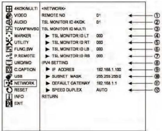
① REMOTE number
- Set the ID number for the optional serial remote controller, "SRC-400," and the IR remote controller, "RCT-30A" from 01 through 99.
- Set the ID number which is used during the remote control in the network from 01 through 99.
- Default setting is 01.
② Setting of the monitor ID number for TSL 4K MODE/2K MODE
- Set the monitor ID number of the TSL control using RS485 in 4K MODE and 2K MODE for VIEW MODE.
- No. "0 to 126" is available for setting the ID number.
- The number of units which can be driven by the chain connection is up to 32 units per line. However, up to 126 units can be controlled individually by increasing the number of lines.
- Default setting is 000.
③ Setting of the monitor ID number for TSL MULTI MODE
- When the VIEW MODE is MULTI MODE, the TSL control ID number of each of the four screen areas divided is set by the following items ④ through ⑦. No. "0 to 126" is available for setting the ID number.
- The number of units which can be driven by the chain connection is up to 32 units per line. However, up to 126 units can be controlled individually by increasing the number of lines.
④ TSL MONITOR ID LT setting
- Set the TSL ID number at the upper left screen.
- Default setting is 000.
⑤ TSL MONITOR ID RT setting
- Set the TSL ID number at the upper right screen.
⑥ TSL MONITOR ID LB setting
- Set the TSL ID number at the lower left screen.
⑦ TSL MONITOR ID RB setting
- Set the TSL ID number at the lower right screen.
⑧ IPV4 SETTING setting
- Following items ⑨ through ⑫ are used for the setting of Ethernet network.
⑨ IP ADDRESS setting
• Example 192.168.1.100
⑩ SUBNET MASK setting
• Example 255.255.255.0
⑪ DEFAULT GATEWAY setting
• Example 1192.168.1.1
⑫ SPEED / DUPLEX setting
- Setting of communication method
• AUTO, 100M FULL, 100M HALF
4-15. Description of MENU-RESET Functions
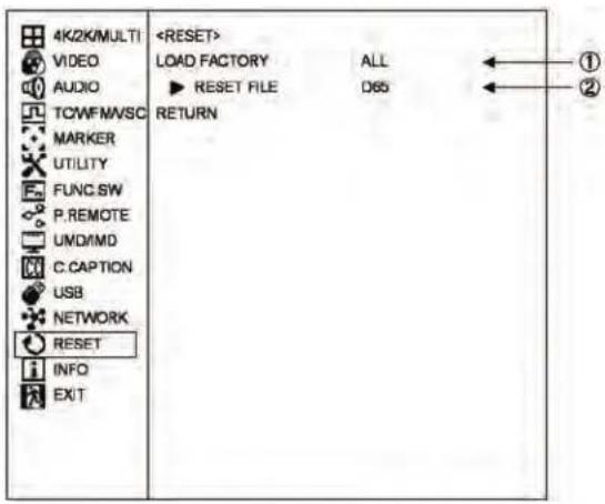
① Executing the initialization of setup data
- Perform this setting to restore the default settings.
- ALL : Factory settings are restored for all PRESET data, all MENUs and switches.
- PRESET : Factory settings are restored for all PRESET data.
- MENU&SW : Factory settings are restored for all MENUs and switches.
- To initialize, select an item to be initialized with the UP DOWN and press the ENT. The confirmation message appears. Press the ENT again. To cancel the initialization, just press the ESC switch.
* The initialization of data cannot be executed if "PRESET LOCK" or "ALL LOCK" is set in "MENU-SYSTEM LOCK-UTILITY".
To initialize the data, unlock the settings.
- Default setting is ALL.
② Selecting the preset files to be initialized
- When "PRESET" is selected in ①, select a file for restoring the setup data to the factory-settings.
- ALL : All the preset files are initialized.
- FILEx : FILEx only is initialized. (x:1 to 8)
- FILE1-8 : FILE1 to FILE8 only are initialized.
· D65 : REF D65 only is initialized.
· D93 : REF D93 only is initialized. - D65/D93 : REF D65 and D93 only are initialized.
· ACES : REF ACES only is initialized. - DCIP3 : REF DCIP3 only is initialized.
- Default setting is D65.
4-16. Description of MENU-INFO Functions (1) INFO (1/2)

① Displaying the format
• Displays the format of the signal being displayed.
② Displaying the payload
- Displays the payload data of the signal being displayed.
③ Displaying the model name
- Displays model name.
④ Displaying the file name
• Displays the name of the file being set.
⑤ Displaying the backlight value
• Displays the set backlight value.
⑥ Displaying the view mode
• Displays the set view mode.
⑦ Displaying of F1 switch assignment function
- Displays the function assigned to the F1 switch.
⑧ Displaying of F2 switch assignment function
- Displays the function assigned to the F2 switch.
⑨ Displaying of F3 switch assignment function
- Displays the function assigned to the F3 switch.
⑩ Displaying of F4 switch assignment function
- Displays the function assigned to the F4 switch.
⑪ Displaying the power on status
• Displays the set power on status.
⑫ Displaying the main MPU version
- Displays the current main MPU version.
⑬ Displaying the sub MPU version
- Displays the current sub MPU version.
⑭ Displaying the FPGA1 version
- Displays the current FPGA1 version.
⑮ Displaying the FPGA2 version
• Displays the current FPGA2 version.
⑯ Displaying the FPGA3 version
- Displays the current FPGA3 version.
(2) INFO (2/2) - PAYLOAD INFO
Display information on payload relation.
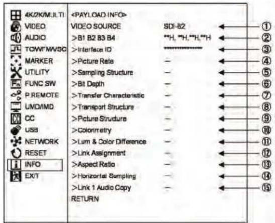
① VIDEO SOURCE
- Displays a source name which indicates the payload information.
. When VIDEO SOURCE is SDI-B1/2/3/4 in 4K MODE, or when in MULTI MODE, displayed source can be toggled by pressing ENT.
② B1 B2 B3 B4
• Each of payload Byte 1 to Byte 4 is displayed.
③ Interface ID
- The interface ID is extracted from the payload values and displayed.
④ Picture Rate
- The picture rate information is extracted from the payload values and displayed.
⑤ Sampling Structure
- The sampling structure information is extracted from the payload values and displayed.
⑥ Bit Depth
- The bit depth information is extracted from the payload values and displayed.
⑦ Transfer Characteristic
- The transfer characteristic information is extracted from the payload values and displayed.
⑧ Transport Structure
- The transport structure information is extracted from the payload values and displayed.
⑨ Picture Structure
- The picture structure information is extracted from the payload values and displayed.
⑩ Colorimetry
- The color space information is extracted from the payload values and displayed.
⑪ Lum & Color Difference
- The information regarding color difference signal calculating method is extracted from the payload values and displayed.
⑫ Link Assignment
- The information regarding link assignment numbers is extracted from the payload values and displayed.
⑬ Aspect Ratio
- The picture aspect ratio information is extracted from the payload values and displayed.
⑭ Horizontal Sampling
- The number of horizontal pixels of picture is extracted from the payload values and displayed.
⑮ Link1 Audio Copy
- Whether or not Link 1 audio is copied from the payload values is displayed.
- When it is ON, Link 1 audio is embedded to the source. When it is OFF, original audio is embedded.
5. Preset Menu Function
5-1. List of preset menu
- To execute the preset menu, press PRESET switch.
* Turn off the menu screen.

flowchart
graph TD
    A["SELECT FILE"] --> B["D65"]
    C["FILE REFERENCE"] --> D["INPUT"]
    E["BACKLIGHT DIM."] --> F["9"]
    G["COLOR SPACE"] --> H["BT.709"]
    I["YCbCr MATRIX"] --> J["BT.709"]
    K["EOFT"] --> L["2.2"]
    M["HLG TONEMAP"] --> N["MODE1"]
    O["HLG VARIABLE"] --> P["1000"]
    Q["HLG CLIP(R/G/B)"] --> R["100 / 100 / 100"]
    S["MASTER CLIP"] --> T["100"]
    U["CHANGE FILE"] --> V["11"]
    W["COPY FILE"] --> X["12"]
    Y["EXIT"] --> Z["PRESET CHANGE FILE D65"]
    AA["PRESSET COPY FILE"] --> AB["FROM D65"]
    AA --> AC["TO FILE"]
    AA --> AD["EXECUTE"]
    AA --> AE["RETURN"]
    B --> F
    D --> H
    F --> H
    H --> J
    J --> L
    L --> N
    N --> R
    R --> T
    T --> X
    X --> Y
    Y --> Z
    Z --> AA
① Selection of files
- Select a file from among D65, D93, ACES, DCI P3 and FILE1 to FILE8.
• D65 : for 6500K files
• D93 : for 9300K files
- ACES : for ACES files
- DCI P3 : for DCI P3 files
- FILE1 to 8 : User files
• The following data is memorized in these 10 files.
- CHROMA : CHROMA data
· BRIGHT : BRIGHTNESS data - CONT : CONTRAST data
• R.GAIN : R.GAIN data
• G.GAIN : G.GAIN data
· B.GAIN : B.GAIN data
• R.BKG : R.BACKGROUND data
• G.BKG : G.BACKGROUND data
• B.BKG : B.BACKGROUND data
* The D65 and D93 have been factory-set for the color temperatures of 6500K and 9300K, respectively. The FILE1 thru -8 data have been factory-set to be the same as for the D65.
- Default setting is INPUT.
② Setting a file change at the time of channel change
- Set the association of channel change with file change.
- INPUT: Files are memorized for each channel: When a channel is changed to another, the stored file is recalled automatically.
- COMMON: Just one preset file is fixed for all channels.
- Default setting is INPUT.
③ Setting the backlight brightness level
- Set the brightness of the backlight at 1 to 30 levels. (Fixed to 30 for HDR)
- When the backlight brightness level is raised, the black level is also slightly raised. Therefore set the backlight brightness level according to the ambient condition.
- This function can be assigned to a function switch on the front panel.
* The rough setting target of brightness (160 cd/m²) specified in Adobe RGB is 10. (when the contrast is in default setting)
* Use at lower backlight brightness level extends the life span of the backlight.
- Default setting are as follows.
SDR mode : 9
HDR mode : 30(fixed)
④ COLOR SPACE setting
- The color gamut corresponding to each standard is set.
- AUTO: Judge the BT.2020/709 color gamut from the payload and set automatically.
- BT.2020: Color gamut corresponding to ITU-R BT.2020
- BT.709: Color gamut corresponding to ITU-R BT.709
• DCI-P3 D65: Color gamut corresponding to DCI-P3 D65 - DCI-P3: Color gamut corresponding to DCI-P3
• ACES: Color gamut corresponding to ACES - Adobe RGB: Color gamut corresponding to Adobe RGB
• PANEL: Color gamut of the panel itself
• LOG G1: Color gamut corresponding to LOG G1
• LOG G2: Color gamut corresponding to LOG G2
- Default setting is BT.709.
HQLM-1720WR
⑤ YCbCr MATRIX setting
- YCbCr matrix is set.
AUTO : Automatically judge the conversion matrix by the payload,
BT.2020: Setting corresponding to ITU-R BT.2020
BT.709 : Setting corresponding to ITU-R BT.709
- Default setting is BT.709.
⑥ EOTF setting
• EOTF gamma curve is set.
AUTO : Either one of HLG1/PQ is automatically judged from the payload.
HLG1 : HLG method gamma (with OOTF processing)
HLG2 : HLG method gamma (without OOTF processing)
LOG1 : LOG1 setting gamma
LOG2 : LOG2 setting gamma
PQ : PQ method gamma
ACES P. : ACES Proxy gamma
| 2.2 | : | Gamma | 2.2 |
| 2.4 | : | Gamma | 2.4 |
| 2.6 | : | Gamma | 2.6 |
- Default setting is 2.2.
⑦ TONEMAP setting
- In the case of HLG1/HLG2/LOG1/LOG2/PQ/ACES.P, compressed by the curve from a certain level so that the high luminance signal subsides to the maximum brightness of the panel.
MODE1 It is uncompressed to a certain level. but compress at a higher level.
MODE2 Compression from the lower level compared to the MODE1.
MODE3 Compress full Range..
MODE4 Does not compress. and clip with the maximum brightness of the panel.
- Default setting is MODE2.
⑧ HLG VARIABLE setting
• The maximum brightness to HLG1 gamma curve is set from 800 / 900 / 1000 / 1100 / 1200 cd/m2.
- Default setting is 1000.
⑨ HLG CLIP (R/G/B) setting
- By the setting when EOTF is "HLG1 / 2," the clip point at high bright section of R/G/B is set.
The set value 100 is a condition without a clip. The number of clips increases as the number is equal to or less than 100.
- Default setting is 100/100/100.
⑩ MASTER CLIP setting
- In addition to the setting in ⑨, the clip point of high bright section where R/G/B is simultaneously operated is set.
The set value 100 is a condition without a clip. The number of clips increases as the number is equal to or less than 100.
- Default setting is100.
⑪ Change of preset data
| PRESET CHANGE FILE D65 | |
| CHROMA | 100 |
| BRIGHT | 0.0 |
| CONTRAST | 89.0 |
| R.BKG | 0.0 |
| G.BKG | 0.0 |
| B.BKG | 0.0 |
| R.GAIN | 100.0 |
| G.GAIN | 100.0 |
| B.GAIN | 100.0 |
| RETURN | |
- Change the data of a file selected in "① Selection of files".
- How to change data Select "CHANGE FILE" and press the ENT.
The following "PRESET CHANGE FILE" menu appears.
- For details, refer to Item "How to change PRESET data".
- Adjustable
- CHROMA
Used to set the color density.
Variable range: 0\~200
- Default setting is 100.
· BRIGHT (BRIGHTNESS)
Used to set the black level.
Variable range : -60.0\~+60.0
- Default setting is 0.0.
- CONT (CONTRAST)
Used to set the white level.
Variable range: 0.0\~120.0 (WIDE: 0.0\~200.0)
- Default setting is 100.
• R.BKG (R.BACKGROUND)
Used to set the black balance (red component) at dark level.
Variable range : -25.0\~+25.0
- Default setting is 0.0.
· G.BKG (G.BACKGROUND)
Used to set the black balance (green component) at dark level..
Variable range : -25.0\~+25.0
- Default setting is 0.0.
· B.BKG (B.BACKGROUND)
Used to set the black balance (blue component) at dark level..
Variable range : -25.0\~+25.0
- Default setting is 0.0.
• R.GAIN
Used to set the white balance (red component) at bright level.
Variable range: 0.0\~200.0
- Default setting is 100.0.
• G.GAIN
Used to set the white balance (green component) at bright level.
Range: 0.0\~200.0
- Default setting is 100.0.
• B.GAIN
Used to set the white balance (blue component) at bright level.
Range: 0.0\~200.0
- Default setting is 100.0.
⑫ Copying of file data
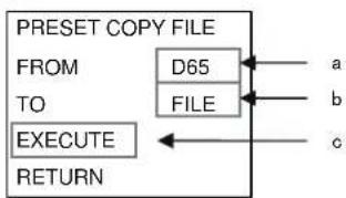
flowchart
graph TD
    A["PRESET COPY FILE"] --> B["FROM"]
    B --> C["TO"]
    C --> D["EXECUTE"]
    D --> E["RETURN"]
    F["D65"] --> G["FILE"]
    H["a"] --> I
    J["b"] --> K
    L["c"] --> M
(a) Select the source file (D65, D93, FILEx [x: 1 to 8]) using the ENT.
(b) Select the destination for the file (FILEx [x: 1 to 8], FILE1 - FILE8) using the UP DOWN.
* When FILE1 - FILE8 are selected, data is copied to FILE1 through FILE8.
(c) When the ENT is pressed, the copy confirmation message appears. To copy, press the ENT again.
If not, press the ESC switch.
How to change PRESET data

flowchart
Data registration and data clearing flowchart for PRESET change files, covering file selection, data validation, and data clearance steps.6. Mouse menu function
6-1. Basic procedure of the mouse menu
Basic behavior of the mouse
The USB mouse requires the following 4 functions. Remote control is enabled using a 2.4GHz wireless mouse.

flowchart
graph TD
    A["Move cursor"] --> B["Data variable"]
    C["Move cursor"] --> D["Data variable"]
    E["ENT"] --> F["Switching Point"]
    G["ESC"] --> F
    B --> H["Switching Point"]
    D --> H
    F --> H

①Double click
- The mouse menu is display.

②Left click
• A selected item on the menu is moved to the right.
• The data is registered.

③Right click
• A selected item in the menu is moved to the left.
- The data is cleared.

④Scroll wheel
•The mouse menu is enlarged
-The data is modified.

flowchart
graph TD
    A["<Normal screen>"] --> B["<MOUSE MENU> MENU PRESET FUNCTION"]
    B --> C["<MOUSE MENU> MENU PRESET FUNCTION"]
    C --> D["<MOUSE MENU> MENU PRESET FUNCTION"]
    D --> E["<Normal screen>"]
    style A fill:#f9f,stroke:#333
    style B fill:#ccf,stroke:#333
    style C fill:#cfc,stroke:#333
    style D fill:#fcc,stroke:#333
① The MAIN menu is displayed All operations of MENU are possible.

② The PRESET menu is displayed. All operations of PRESET MENU are possible.
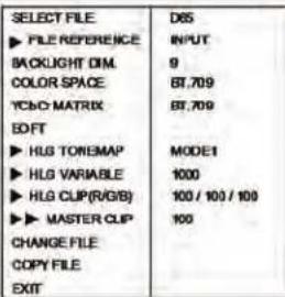
④ The FUNCTION menu is displayed. All the switches on the front operation section can be controlled.
1 : (binak)
2 : (blank)
3 : (balnk)
4 : (blank)
MONO
MARKE
APERTURE
SCREEN
6-2. Basic procedures on the MENU and PRESET MENU screens
① Basic mouse behavior on the MENU screen

flowchart
graph TD
    A["Move"] --> B["Select"]
    B --> C["Select"]
    C --> D["Return"]
    D --> E["Data modify"]
    E --> F["Return"]
    F --> G["Select"]
    G --> H["Select"]
    H --> I["Return"]
    I --> J["Data modify"]
    J --> K["Return"]
    K --> L["Select"]
    L --> M["Select"]
    M --> N["Move"]
    style A fill:#f9f,stroke:#333
    style B fill:#ccf,stroke:#333
    style C fill:#cfc,stroke:#333
    style D fill:#fcc,stroke:#333
    style E fill:#cff,stroke:#333
    style F fill:#ffc,stroke:#333
    style G fill:#cfc,stroke:#333
    style H fill:#fcc,stroke:#333
    style I fill:#ffc,stroke:#333
    style J fill:#fcc,stroke:#333
    style K fill:#ffc,stroke:#333
    style L fill:#cfc,stroke:#333
    style M fill:#fcc,stroke:#333
- Left-click the mouse to go to the right of the MENU screen and select an item. Right-click it to return to the left-hand items.
- The scroll wheel is used to move vertically and to change the settings.
- When there are two or more settings to select on the right-hand data like the USB memory's date setting, left-click the mouse to go to the settings to modify.
③ Basic mouse behavior on the CHANGE PRE-SET screen
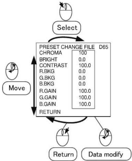
flowchart
graph TD
    A["Move"] --> B["Select"]
    B --> C["PRESET CHANGE FILE D65"]
    C --> D["CHROMA 100"]
    C --> E["BRIGHT 0.0"]
    C --> F["CONTRAST 100.0"]
    C --> G["R.BKG 0.0"]
    C --> H["G.BKG 0.0"]
    C --> I["B.BKG 0.0"]
    C --> J["R.GAIN 100.0"]
    C --> K["G.GAIN 100.0"]
    C --> L["B.GAIN 100.0"]
    C --> M["RETURN"]
    M --> N["Return"]
    M --> O["Data modify"]
• The behavior is the same as Item ①.
② Basic mouse behavior on the PRESET MENU
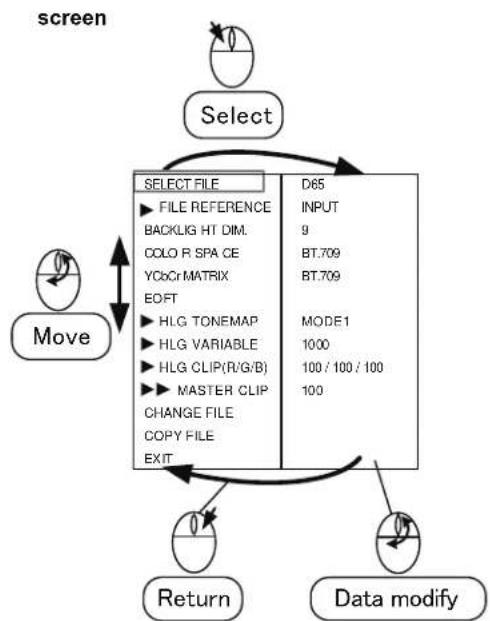
flowchart
graph TD
    A["Screen"] --> B["Select"]
    B --> C["Move"]
    C --> D["Return"]
    D --> E["Data modify"]
    E --> F["SELECT FILE"]
    F --> G["FILE REFERENCE"]
    G --> H["BACKLIG HT DIM."]
    H --> I["COLO R SPA CE"]
    I --> J["YCbCr MATRIX"]
    J --> K["EOFT"]
    K --> L["HLG TONEMAP"]
    L --> M["HLG VARIABLE"]
    M --> N["HLG CLIP(R/G/B)"]
    N --> O["MASTER CLIP"]
    O --> P["CHANGE FILE"]
    P --> Q["COPY FILE"]
    Q --> R["EXIT"]
    R --> S["D65"]
    S --> T["INPUT"]
    T --> U["9"]
    U --> V["BT.709"]
    V --> W["BT.709"]
    W --> X["MODE1"]
    X --> Y["1000"]
    Y --> Z["100 / 100 / 100"]
    Z --> AA["100"]
• The behavior is the same as Item ①.
④ Basic mouse behavior on the USER MARKER screen

flowchart
graph TD
    A["Move"] --> B["Data modify"]
    B --> C["Return"]
    C --> D["Scroll up"]
    D --> E["Data clear (-)"]
    F["Select"] --> G["<<SETTING OF USER MARKER>>"]
    G --> H["PAGE1"]
    H --> I["SCENE NAME"]
    I --> J["No. SW COL DATA(X Y)"]
    J --> K["MK1 ON S: ____<br>MK2 OFF S: ____<br>MK3 OFF S: ____<br>MK4 OFF S: ____<br>MK5 OFF S: ____<br>MK6 OFF S: ____<br>NEXT PAGE"]
    K --> L["Data clear (-)"]
• The behavior is the same as Item ①.
7. Specifications
7-1. General specifications
(1) Supply voltage
AC input
· 100 V-120 V±10 % 50/60 Hz
· 200 V-240 V±10 % 50/60 Hz
(2) Power consumption
AC input: 120 Wmax
(3) Ambient operating temperature/humidity, ambient storage temperature/humidity
Operation: 0 °C to +40 °C / 20 % to 85 % (no condensing)
Storage: -20 °C to +60 °C / 5 % to 85 % (no condensing)
(4) Outside dimensions (excluding protrusions) 428(W)*309(H)*145 mm(D), 8U
(5) Weight (excluding the stand and option)
Main chassis : Approx. 8.5 kg Stand : Approx. 1.0 kg
(6) Standard accessories
Operation manual, parallel remote connector, AC Power cable x1 each
7-2. Rated performance
(1) SDI signal
a) Input terminal
12G/3G/HD : BNC 2 lines
3G/HD : BNC 3 lines
800 mVp-p ± 10 % 75 Ω
b) Output terminal
12G/3G/HD : BNC 2 lines
3G/HD : BNC 3 lines
800 mVp·p±10 % 75 Ω
c) Input signal format (Auto detection)
· HD-SDI
1920x1080
59.94i,29.97p,23.98p,29.97psf,23.98psf
50i,25p,24p,25psf,24psf,60i,30p,30psf
1280x720
59.94p,29.97p,23.98p,29.97psf,23.98psf
50p,25p,24p,25psf,24psf,60p,30p,30psf
2048x1080
29.97p,23.98p,29.97psf,23.98psf
25p,24p,25psf,24psf,30p,30psf
· 3G-SDI
1920x1080
59.94p,50p,60p
2048x1080
59.94p,47.95p,50p,48p,60p
· 3G-SDIx4 Quad Link 4K
3840x2160
59.94p,29.97p,23.98p,29.97psf,23.98psf
50p,25p,24p,25psf,24psf,60p,30p,30psf
4096x2160
59.94p,29.97p,23.98p,29.97psf,23.98psf
50p,25p,24p,25psf,24psf,60p,30p,30psf
· 12G-SDI
3840x2160
59.94p,47.95p,29.97p,23.98p,
50p,48p,25p,24p,60p,30p
4096x2160
59.94p,47.95p,29.97p,23.98p,
50p,48p,25p,24p,60p,30p
* See "Data1 Input Signal Compatible Formats".
d) Embedded audio
Sampling frequency : 48 kHz
(Synchronized with video clock)
e) Embedded audio output
By selecting one pair of channels from ch1/2 - ch15/16 and DOWNMIX, the audio can be output from the analog audio outputs, the headphone output terminal, and built-in stereo speakers.
(2) HDMI signal
a) Input terminal
HDMI 1 line
b) Input signal format
1920x1080
59.94i,29.97p,23.98p
50i,25p,24p,24psf,60i,30p
1280x720
59.94p,50p,60p
3840x2160
59.94p,29.97p,23.98p
50p,25p,24p,60p,30p
4096x2160
59.94p,29.97p,23.98p
50p,25p,24p,60p,30p
640x480
59.94p,60p
720x480
59.94p,60p
720x567
50p
* See "Data1 Input Signal Compatible Formats".
c) HDCP
HDCP2.2 support
d) Audio format
L-PCM
HQLM-1720WR
e) Audio output
By selecting one pair of channels from ch1/2, ch3/4, ch5/6, and ch7/8 and DOWNMIX, the audio can be output from the analog audio outputs, the headphone output terminal, and built-in stereo speakers.
(3) Analog audio output
a) Output terminal RCA 2 line
b) Output level 0dBV max (digital audio data: at the 0dBFS) *0dBV=1Vrms
c) Output impedance 10 or more
d) Input signal source Analog audio input or embedded audio input can be output. The signal to be output is set on "MENU-AUDIO".
(4) Headphones output
a) Output terminal Φ3.5 Stereo mini jack type
b) Output 85 mW/ch (RL: 32 Ω)
c) Input signal source Analog audio signal or embedded audio signal can be output. To select one of these signals, make the setting in “MENU-AUDIO-LINE/SP CH”.
(5) Speaker output
a) Rated output (2 channel) 1W+1W or more
b) Input signal source Analog audio input or embedded audio input can be output. A signal to be outputted is set in "MENU-AUDIO-LINE/SP CH".
* With the headphones connected, no sound is heard from the speakers.
(6) Color temperature setting
12 types: D65, D93, ACES, DCI P3 and USER setting: 8 types (FILE 1 to 8)
(7) EOTF
ITU-R BT.2100 (HLG)
SMPTE ST.2084 (PQ)
2.2
2.4
2.6
LOG1
LOG2
ACES Proxy
* Auto or manual setting is possible with PRESET MENU.
(8) Color space
ITU-R BT.2020※
ITU-R BT.709
DCI P3 D65※
DCI P3※
ACES※
Adobe RGB※
LOG G1
LOG G2
* Auto or manual setting is possible with PRESET MENU.
* RGB color points are not fully included.
7-3. Specifications for LCD Panel
(1) Number of pixels
3840 (H) x 2160 (V) dots
(2) Screen size (display area)
381.888 mm(H) x 214.812 mm(V)
16:9 aspect : Diagonal 43.6 cm, 17.3Vtype
(3) Peak Brightness (brightness performance for a single panel)
450 cd/m² typ. ✉ Maximum brightness
(4) Contrast ratio
800:1 typ.
(5) Panel tone
RGB 8 bit each
(6) Number of display colors
16,777,216 colors
(7) Viewing angle
Vertical/horizontal : 178°
(Contrast ratio 10:1 or more)
(8) Top polarizer type
Anti-Glare
7-4. Applicable Standerds
(1) Safety standards
· UL60950-1
· EN60950-1
(2) Electromagnetic interface
• VCCI (Class-A)
- FCC (Class-A)
• EN55032 (Class-A)
· EN55103-2 E4
(3) Specific chemical substance regulation
• RoHS Directive compliance
(4) Confirmation of HDMI ATC testing
· HDMI CTS version 1.4b and 2.0u
7-5. Functions
(1) Front operation
a) Switch
(Set to ON/OFF using the MENU)
b) Safety marker
Any of the following markers is displayed according to the image aspect ratio.
Safety area marker
- "Safety area marker" + 100 %
The “safety area markers” are effective over the entire screen and can be preset in 1 % increments in the range of 80-99 %.
- 5 divided crosshatch
• 10 divided crosshatch - Cross
• 16:9 aspect marker
• 15:9 aspect marker
• 14:9 aspect marker
• 13:9 aspect marker
• 4:3 aspect marker
• 1.85:1 aspect marker
• 2.35:1 aspect marker - “Each aspect marker” + “Safety marker in aspect”
The “safety marker in aspect” refers to the safety marker with respect to the aspect marker display zone, and can be preset in 1 % increments in the range of 80-99 %.
Corresponding to each aspect marker.
- Set in five steps of 20%, 40%, 60%, 80% and 100%
(3) Shadow function
Creates a shadow outside the aspect areas with 4:3, 13:9, 14:9, 15:9, 16:9, 1.85:1 and 2.35:1.
"Various aspect markers" + "Shadow"
"Various aspect markers" + "Safety marker in aspect" + "Shadow"
Shadow only
Set in four steps of 0 %, 20 %, 40 % and 60 %.
(4) User marker function
Function for the user to draw their desired lines and boxes in the unit of pixels.
a) No. of types: 10 scenes x 12 types (1 scene: 12 types)
b) No. of colors: 7
c) Drawable sizes: 3840x2160 pixels
d) Drawing method: SW or USB mouse
* Patent acquisition
(5) UMD/IMD display with TSL protocol
Character display function controlled by RS485.
Either TSL or user display should be selected for the UMD/IMD display (MENU selection).
a) Standard: RS485
b) Connector: R J-45 (loop through)
c) Number of connections: up to 32 devices (per line)
d) Protocol: TSL UMD V3.1
e) Characters: ASCII (alphanumeric), up to 8 characters, 7 colors
f) TALLY display: Red/Green/Amber
g) Display in the screen or LED display
Display position: Top/bottom
(6) UMD/IMD display with user display
A function used to set a material name on a channel basis (SDI-A1, SDI-B1, SDI-B2, SDI-B3, SDI-B4, SDI-B1/B2/B3/B4 and HDMI) and display the material name when switching the inputs.
a) Characters: ASCII (alphanumeric), up to 8 characters, 7 colors
b) Display position: Top/bottom
(7) USB memory function
a) Contents of the memory
MENU setting
- User marker
- PRESET data
(8) Embedded audio level meter
a) Display method Superimposed on screen
b) Display channel 8 ch (max) The display can be selected from “ch1 to 2, ch1 to 4, ch1 to 8, ch9 to 10, ch9 to 12, ch9 to 16”.
c) Display position 4 types
d) Display mode 8 modes
c) Display segment 52 segments (including -∞)
f) Display color Reference level (-18 dBFS or -20 dBFS) is selected in the MENU.
-20 dBFS -∞ to -22 dBFS : Green -20 to -2 dBFS : Yellow 0 dBFS : Red
- -18 dBFS -∞ to -20 dBFS : Green -18 to -2 dBFS : Yellow 0 dBFS : Red
g) Peak hold
About 1 sec
* It can be set to "OFF" in the MENU.
h) Release time
About 0.4 sec
(9) Multi-screen display
When 2K / HD format signal is input, the following multi-screen displays are possible using CH·B1 \~ CH·B4 input.
When "3 MULTI" and "2 MULTI" mode, WFM and vector scope can be displayed in the vacant area.
(10) WFM monitor display
a) Single channel display Select from Y, Cb, Cr, R, G, B
b) Component display Select from Y/Cb/Cr, RGB
c) Display size 256 x 256 384 x 384
d) Display color White
Y G : Green
Cb B : Blue
Cr R : Red
(11) Vector scope display
a) Display size 256 x 256 384 x 384
b) Display color White, Green
(12) Time code display
a) Supported signal fomat 3G/HD-SDI signal
b) Type VITC, LTC
c) Conforming standard SMPTE RP-188
d) Display size 2type
(13) Closed caption display
a) Supported signal format 3G/HD-SDI signal
b) Conforming standard SMPTE 334-1, SMPTE 334-2 CEA-708, CEA-608
(14) Automatic switching by payload of HDR and color space
a) Supported format 12G/3G/HD-SDI signal payload
b) Conforming standard ITU-R BT.2077 ITU-R BT.1120·9
7-6. Remote Control
(1) Parallel remote control Input connector: HD D-SUB 15-pin For the pin function, refer to "Data2 Parallel Remote Pin Function".
(2) Serial (RS-485) remote control (The SCR-400 controller is optional.)
a) Connector: RJ-45 (loop-through)
b) Maximum number of connections: 32 units Extension by increasing the number of lines is possible.
c) Interface: RS-485
* See "Data4: Control with remote controller" for the control items."
(3) Wireless remote control (The RCT-30A controller is optional.)
* See "Data4: Control with remote controller" for the control items."
(4) Ethernet remote control For details of this function please refer to another document.
8. Mounting
Equipped with "100 x 100 mm" mounting holes compliant with the VESA mount interface standard.
Other mounting holes also available.
(Refer to the "10. External View".)
9. Options
(1) RCT-30A
“Infrared remote controller” Just this unit can control most of the monitor functions. Up to 99 monitors can be controlled individually.
(2) SRC-400
"Serial remote controller"
A serial remote controller that allows you to remote control the monitor with RS485 interface by loop-through connection via LAN cable.
One controller can control all functions of monitors. By connecting the monitors with the loop-through connection via LAN cable, one line can control 32 monitors, and three lines can control up to 96 monitors individually or all at once.
Since the controller can be also connected with PC and Ethernet, it is possible to individually control each monitor from the PC screen through network control.
• Weight: approx. 0.83Kg
• Color: black
* The specifications and appearance of this product are subject to change for product improvement without notice.
(3) Handle, Fixed stand, Fixed rack mount adapter
Please select the following option according to usage method and installation location.
- Handle GR-1720
- Fixed stand STD-1720
- Tilted stand STD-1720T
• Fixed rack mount adapter RS1770 - Tilted fixed rack mount adapter RS1770T
- Blank panel RS-1770T-BP
For details, refer to “10 External view” 10-2 to 10-5.
10. External View [UNIT : mm]
10.1 Without option

10.2 Fixed stand STD-1720 with handle GR-1720


10.3 Tilted stand with STD-1720T

natural_image
Technical line drawing of a mechanical device with dimension annotations (15° and 8°), no readable text or symbols present.
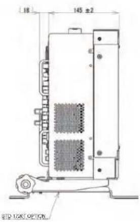
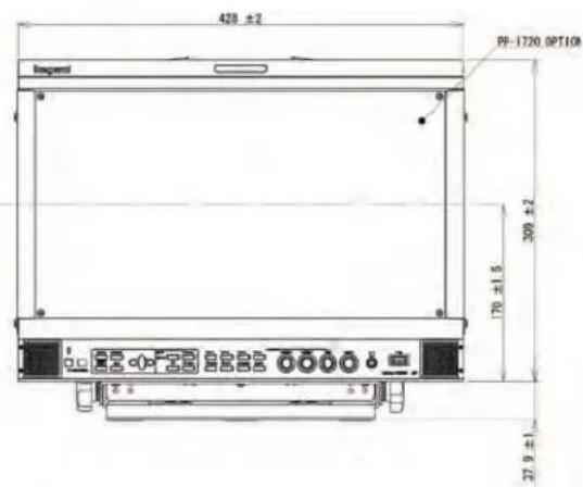
10.4 Fixed rack mount with adapter RS-1770

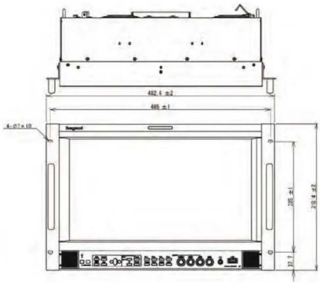
10.5 Tilted fixed rack mount adapter RS-1770T, with a blank panel RS-1770T-BP
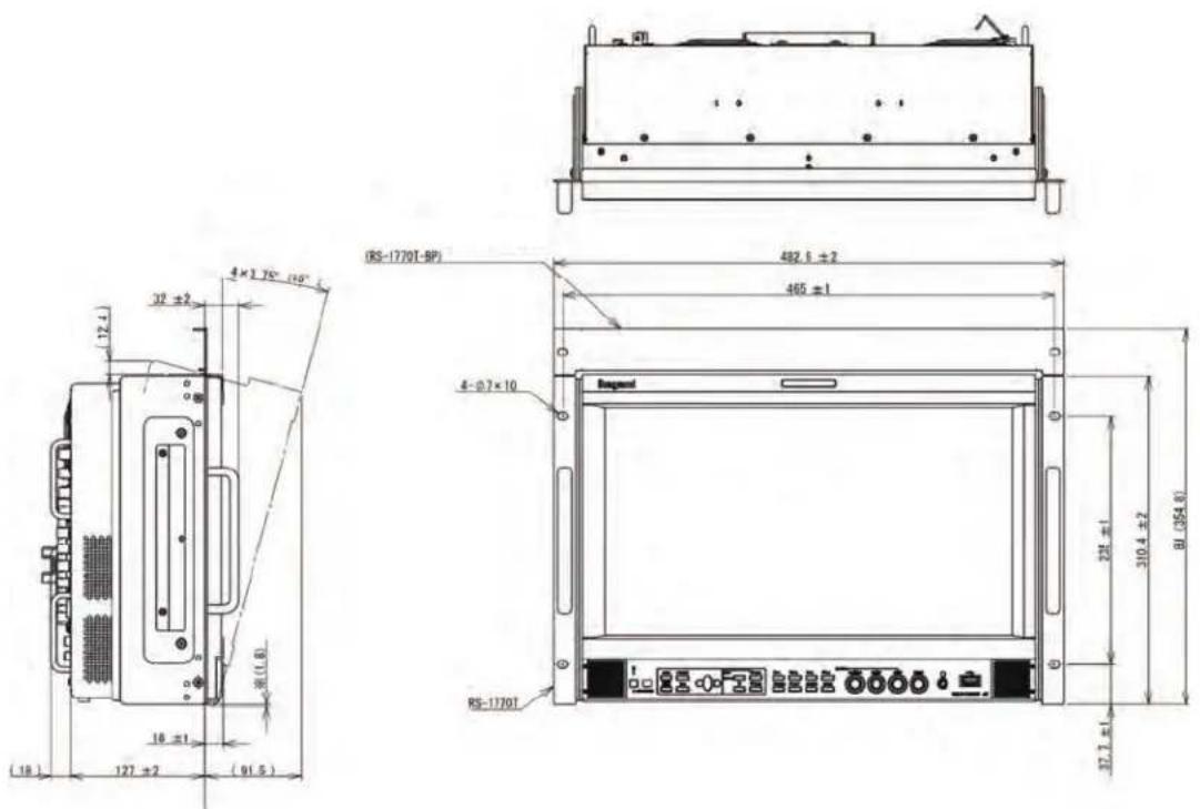
- When installing this system, a space of EIA 8U size is required.
- Use a dedicated blank panel, RS-1770T-BP.
- When the system is tilted for 15^ , the lower section of the system body (section with * mark) pops out for approximately 1.8 mm downward. Therefore, if the system is mounted at the lower section, and if the projecting section interfere, mount the system at an angle of 7.5^ or lower.
Data 1 Input Signal Compatible Formats
| INPUT Signal | system Signal format | |||
| HD-SDI | 1920 | × | 1080/60i/59.94i 4:2:2 YCbCr 10bit | |
| HD-SDI | 1920 | × | 1080/50i 4:2:2 YCbCr 10bit | |
| HD-SDI | 1920 | × | 1080/30PsF/29.97PsF 4:2:2 YCbCr 10bit | |
| HD-SDI | 1920 | × | 1080/25PsF 4:2:2 YCbCr 10bit | |
| HD-SDI | 1920 | × | 1080/24PsF/23.98PsF 4:2:2 YCbCr 10bit | |
| HD-SDI | 1280 | × | 720/60p/59.94p 4:2:2 YCbCr 10bit | |
| HD-SDI | 1280 | × | 720/50p 4:2:2 YCbCr 10bit | |
| HD-SDI | 1280 | × | 720/30p/29.97p 4:2:2 YCbCr 10bit | |
| HD-SDI | 1280 | × | 720/25p 4:2:2 YCbCr 10bit | |
| HD-SDI | 1280 | × | 720/24p/23.98p 4:2:2 YCbCr 10bit | |
| HD-SDI | 1920 | × | 1080/30p/29.97p 4:2:2 YCbCr 10bit | |
| HD-SDI | 1920 | × | 1080/25p 4:2:2 YCbCr 10bit | |
| HD-SDI | 1920 | × | 1080/24p/23.98p 4:2:2 YCbCr 10bit | |
| HD-SDI | 2048 | × | 1080/30p/29.97p 4:2:2 YCbCr 10bit | |
| HD-SDI | 2048 | × | 1080/25p 4:2:2 YCbCr 10bit | |
| HD-SDI | 2048 | × | 1080/24p/23.98p 4:2:2 YCbCr 10bit | |
| HD-SDI | 2048 | × | 1080/30PsF/29.97PsF 4:2:2 YCbCr 10bit | |
| HD-SDI | 2048 | × | 1080/25PsF 4:2:2 YCbCr 10bit | |
| HD-SDI | 2048 | × | 1080/24PsF/23.98PsF 4:2:2 YCbCr 10bit | |
| Quad Link HD-SDI | 3840 × 2160/30p/29.97p | 4:2:2 YCbCr 10bit SQD | ||
| Quad Link HD-SDI | 3840 × 2160/25p | 4:2:2 YCbCr 10bit SQD | ||
| Quad Link HD-SDI | 3840 × 2160/24p/23.98p | 4:2:2 YCbCr 10bit SQD | ||
| Quad Link HD-SDI | 3840 × 2160/30PsF/29.97PsF | 4:2:2 YCbCr 10bit SQD | ||
| Quad Link HD-SDI | 3840 × 2160/25PsF 4:2:2 YCbCr 10bit SQD | |||
| Quad Link HD-SDI | 3840 × 2160/24PsF/23.98PsF | 4:2:2 YCbCr 10bit SQD | ||
| 3G-SDI | 1920 × 1080/60p/59.94p | 4:2:2 YCbCr 10bit Level A/B-DL | ||
| 3G-SDI | 1920 × 1080/50p | 4:2:2 YCbCr 10bit Level A/B-DL | ||
| 3G-SDI | 1920 × 1080/60i/59.94i | 4:4:4 RGB/YCbCr 10/12bit Level A/B-DL | ||
| 3G-SDI | 1920 × 1080/50i | 4:4:4 RGB/YCbCr 10/12bit Level A/B-DL | ||
| 3G-SDI | 1920 × 1080/30p/29.97p | 4:4:4 RGB/YCbCr 10/12bit Level A/B-DL | ||
| 3G-SDI | 1920 × 1080/24p/23.98p | 4:4:4 RGB/YCbCr 10/12bit Level A/B-DL | ||
| 3G-SDI | 1920 × 1080/25p | 4:4:4 RGB/YCbCr 10/12bit Level A/B-DL | ||
| 3G-SDI | 1920 × 1080/30PsF/29.97PsF | 4:4:4 RGB/YCbCr 10/12bit Level A/B-DL | ||
| 3G-SDI | 1920 × 1080/25PsF | 4:4:4 RGB/YCbCr 10/12bit Level A/B-DL | ||
| 3G-SDI | 1920 × 1080/24PsF/23.98PsF | 4:4:4 RGB/YCbCr 10/12bit Level A/B-DL | ||
HQLM-1720WR
| INPUT | Signal | system | Signal format | ||||
| 3G-SDI | 1280 × | 720/60p/59.94p | 4:4:4 RGB/YCbCr | 10bit | Level A | ||
| 3G-SDI | 1280 × | 720/50p | 4:4:4 RGB/YCbCr | 10bit | Level A | ||
| 3G-SDI | 1280 × | 720/30p/29.97p | 4:4:4 RGB/YCbCr | 10bit | Level A | ||
| 3G-SDI | 1280 × | 720/25p | 4:4:4 RGB/YCbCr | 10bit | Level A | ||
| 3G-SDI | 1280 × | 720/24p/23.98p | 4:4:4 RGB/YCbCr | 10bit | Level A | ||
| 3G-SDI | 2048 × | 1080/60p/59.94p | 4:2:2 YCbCr | 10bit | Level A/B-DL | ||
| 3G-SDI | 2048 × | 1080/50p | 4:2:2 YCbCr | 10bit | Level A/B-DL | ||
| 3G-SDI | 2048 × | 1080/48p/47.95p | 4:2:2 YCbCr | 10bit | Level A/B-DL | ||
| 3G-SDI | 2048 × 1080/30p | 4:4:4 RGB/YCbCr | 10/12bit | Level A/B-DL | |||
| 3G-SDI | 2048 × 1080/25p | 4:4:4 RGB/YCbCr | 10/12bit | Level A/B-DL | |||
| 3G-SDI | 2048 × 1080/24p/23.98p | 4:4:4 RGB/YCbCr | 10/12bit | Level A/B-DL | |||
| 3G-SDI | 2048 × 1080/30PsF/29.97p | 4:4:4 RGB/YCbCr | 10/12bit | Level A/B-DL | |||
| 3G-SDI | 2048 × 1080/25PsF | 4:4:4 RGB/YCbCr | 10/12bit | Level A/B-DL | |||
| 3G-SDI | 2048 × 1080/24PsF/23.98PsF | 4:4:4 RGB/YCbCr | 10/12bit | Level A/B-DL | |||
| Quad Link 3G-SDI | 3840 × 2160/60p/59.94p | 4:2:2 YCbCr | 10bit | Level A/B-DL | 2SI/SQD | ||
| Quad Link 3G-SDI | 3840 × 2160/50p | 4:2:2 YCbCr | 10bit | Level A/B-DL | 2SI/SQD | ||
| Quad Link 3G-SDI | 3840 × 2160/30p/29.97p | 4:4:4 RGB/YCbCr | 10/12bit | Level A/B-DL | 2SI/SQD | ||
| Quad Link 3G-SDI | 3840 × 2160/25p | 4:4:4 RGB/YCbCr | 10/12bit | Level A/B-DL | 2SI/SQD | ||
| Quad Link 3G-SDI | 3840 × 2160/24p/23.98p | 4:4:4 RGB/YCbCr | 10/12bit | Level A/B-DL | 2SI/SQD | ||
| Quad Link 3G-SDI | 3840 × 2160/30PsF/29.97PsF | 4:4:4 RGB/YCbCr | 10/12bit | Level A/B-DL | SQD | ||
| Quad Link 3G-SDI | 3840 × 2160/25PsF | 4:4:4 RGB/YCbCr | 10/12bit | Level A/B-DL | SQD | ||
| Quad Link 3G-SDI | 3840 × 2160/24PsF/23.98PsF | 4:4:4 RGB/YCbCr | 10/12bit | Level A/B-DL | SQD | ||
| Quad Link 3G-SDI | 4096 × 2160/60p/59.94p | 4:2:2 YCbCr | 10bit | Level A/B-DL | 2SI | ||
| Quad Link 3G-SDI | 4096 × 2160/50p | 4:2:2 YCbCr | 10bit | Level A/B-DL | 2SI | ||
| Quad Link 3G-SDI | 4096 × 2160/48p/47.95p | 4:2:2 YCbCr | 10bit | Level A/B-DL | 2SI | ||
| Quad Link 3G-SDI | 4096 × 2160/30PsF/29.97PsF | 4:4:4 RGB/YCbCr | 10/12bit | Level A/B-DL | SQD | ||
| Quad Link 3G-SDI | 4096 × 2160/25PsF | 4:4:4 RGB/YCbCr | 10/12bit | Level A/B-DL | SQD | ||
| Quad Link 3G-SDI | 4096 × 2160/24PsF/23.98PsF | 4:4:4 RGB/YCbCr | 10/12bit | Level A/B-DL | SQD | ||
| 12G-SDI | 3840 × 2160/60p/59.94p | 4:2:2 YCbCr | 10bit | Level A | 2SI | ||
| 12G-SDI | 3840 × 2160/50p | 4:2:2 YCbCr | 10bit | Level A | 2SI | ||
| 12G-SDI | 3840 × 2160/30p/29.97p | 4:4:4 RGB/YCbCr | 10/12bit | Level A | 2SI | ||
| 12G-SDI | 3840 × 2160/25p | 4:4:4 RGB/YCbCr | 10/12bit | Level A | 2SI | ||
| 12G-SDI | 3840 × 2160/24p/23.98p | 4:4:4 RGB/YCbCr | 10/12bit | Level A | 2SI | ||
| 12G-SDI | 4096 × 2160/60p/59.94p | 4:2:2 YCbCr | 10bit | Level A | 2SI | ||
| 12G-SDI | 4096 × 2160/50p | 4:2:2 YCbCr | 10bit | Level A | 2SI | ||
| 12G-SDI | 4096 × 2160/48p/47.95p | 4:2:2 YCbCr | 10bit | Level A | 2SI | ||
| 12G-SDI | 4096 × 2160/30p/29.97p | 4:4:4 RGB/YCbCr | 10/12bit | Level A | 2SI | ||
| 12G-SDI | 4096 × 2160/25p | 4:4:4 RGB/YCbCr | 10/12bit | Level A | 2SI | ||
| 12G-SDI | 4096 × 2160/24p/23.98p | 4:4:4 RGB/YCbCr | 10/12bit | Level A | 2SI | ||
HQLM-1720WR
| INPUT | Signal system | Signal format | |
| HDMI 640 | × 480/60p/59.94p | 4:4:4 RGB/YCbCr 8/10/12bit | |
| HDMI 640 | × 480/60p/59.94p | 4:2:2 YCbCr | 12bit |
| HDMI 1280 | × 720/60p/59.94p | 4:4:4 RGB/YCbCr 8/10/12bit | |
| HDMI 1280 | × 720/60p/59.94p | 4:2:2 YCbCr | 12bit |
| HDMI 1920 | × 1080/60i/59.94i | 4:4:4 RGB/YCbCr 8/10/12bit | |
| HDMI 1920 | × 1080/60i/59.94i | 4:2:2 YCbCr | 12bit |
| HDMI 1280 | × 720/50p | 4:4:4 RGB/YCbCr 8/10/12bit | |
| HDMI 1280 | × 720/50p | 4:2:2 YCbCr 12bit | |
| HDMI | 1920 × 1080/50i | 4:4:4 RGB/YCbCr 8/10/12bit | |
| HDMI 1920 | × 1080/50i | 4:2:2 YCbCr 12bit | |
| HDMI 1920 | × 1080/60p/59.94p | 4:4:4 RGB/YCbCr 8/10/12bit | |
| HDMI 1920 | × 1080/60p/59.94p | 4:2:2 YCbCr 12bit | |
| HDMI | 1920 × 1080/50p | 4:4:4 RGB/YCbCr 8/10/12bit | |
| HDMI 1920 | × 1080/50p | 4:2:2 YCbCr 12bit | |
| HDMI 1920 | × 1080/30p/29.97p | 4:4:4 RGB/YCbCr 8/10/12bit | |
| HDMI 1920 | × 1080/30p/29.97p | 4:2:2 YCbCr 12bit | |
| HDMI | 1920 × 1080/25p | 4:4:4 RGB/YCbCr 8/10/12bit | |
| HDMI 1920 | × 1080/25p | 4:2:2 YCbCr 12bit | |
| HDMI 1920 | × 1080/24p/23.98p | 4:4:4 RGB/YCbCr 8/10/12bit | |
| HDMI 1920 | × 1080/24p/23.98p | 4:2:2 YCbCr 12bit | |
| HDMI 3840 | × 2160/60p/59.94p | 4:4:4 RGB/YCbCr 8bit | |
| HDMI 3840 | × 2160/60p/59.94p | 4:2:2 YCbCr 12bit | |
| HDMI | 3840 × 2160/50p | 4:4:4 RGB/YCbCr 8bit | |
| HDMI 3840 | × 2160/50p | 4:2:2 YCbCr 12bit | |
| HDMI 3840 | × 2160/30p/29.97p | 4:4:4 RGB/YCbCr 8/10/12bit | |
| HDMI 3840 | × 2160/30p/29.97p | 4:2:2 YCbCr 12bit | |
| HDMI | 3840 × 2160/25p | 4:4:4 RGB/YCbCr 8/10/12bit | |
| HDMI 3840 | × 2160/25p | 4:2:2 YCbCr 12bit | |
| HDMI 3840 | × 2160/24p/23.98p | 4:4:4 RGB/YCbCr 8/10/12bit | |
| HDMI 3840 | × 2160/24p/23.98p | 4:2:2 YCbCr 12bit |
Data 2 Parallel Remote Pin Functions
Connector Face View on Rear Panel | Wiring of Remote Connector (by default) |
| <Connector on system side>D-Sub 15-pin (male) mini-type*ConnectorCD0115PA100: CVILUX-made*CaseDE-C8-J9-F2-1: Japan Aviation Electronics Industry-made*The above parts or equivalents are supplied as standard. | GND 1V:4K-CH-B1 on 2NC 3G TALLY on 4NC 5CHROMA UP on 6MONO on 7NC 8NC 9NC 10NC 11MARKER on 12SHADOW on 13R TALLY on 14V:4K-CH-A1 on 15 |
Wiring of Remote Connector (by default)
| GND | 1 | |
| V:4K-CH-B1 on | 2 | |
| NC | 3 | |
| G TALLY on | 4 | |
| NC | 5 | |
| CHROMA UP on | 6 | |
| MONO on | 7 | |
| NC | 8 | |
| NC | 9 | |
| NC | 10 | |
| NC | 11 | |
| MARKER on | 12 | |
| SHADOW on | 13 | |
| R TALLY on | 14 | |
| V:4K-CH-A1 on | 15 |
* Notes: Remote control terminals should only be controlled by "short circuit to GND pin" or "open" and not control voltage.
Application of voltage may cause failure.
■ Pin functions by default
| Pin No. | Function | External Assignment for Function |
| 1 | GND | Connecting remote terminals to this pin enables ON control. |
| 2 | V-4K | -CH-B1 on Connect to Pin 1 to switch the input (4K mode) setting to CH-B1 (12G-SDI). |
| 3 | NC No connection | |
| 4 | G TALLY on | Connect to Pin 1 to set G TALLY to ON. |
| 5 | NC No connection | |
| 6 | CHROMA UP on | Connect to Pin 1 to set CHROMA GAIN UP function to ON. |
| 7 | MONO on | Connect to Pin 1 to switch the COLOR/MONO setting to MONO. |
| 8 | NC No connection | |
| 9 | NC No connection | |
| 10 | NC No connection | |
| 11 | NC No connection | |
| 12 | MARKER on Connect to Pin 1 to set MARKER to ON. | |
| 13 | SHADOW on Connect to Pin 1 to set SHADOW to ON.* The shadow is displayed in the “MENU-MARKER” -preset level. | |
| 14 | R TALLY on Connect to Pin 1 to set Red TALLY to ON. | |
| 15 | V-4K-CH-A1 on Connect to Pin 1 to switch the input (4K mode) setting to CH-A1 (12G-SDI). |
* Functions explained in this table can be allocated to any pins in the same way as the user setting function in the next section.
■ Additional user-set functions
Functions in "Pin function in the default condition" described in the preceding section and the following functions can be allocated to any desired pin.
| Pin No. Function External Assignment for Function | ||
| User setting | SHADOW0 on | Connect to Pin 1 for running with shadow level 0% (black).* Priority is given to this pin function if any other shadow setting pin is pressed at once. |
| User setting | SHADOW20 on Connect to Pin 1 for running with shadow level 20%. | |
| User setting | SHADOW40 on Connect to Pin 1 for running with shadow level 40%. | |
| User setting | SHADOW60 on Connect to Pin 1 for running with shadow level 60%. | |
| User setting | J.MRK SCENE01 | Connect to Pin 1 to set USER MARKER (SCENE01) to on. It turns off when the connection is opened. |
| User setting | J.MRK SCENE02 | Connect to Pin 1 to set USER MARKER (SCENE02) to on. It turns off when the connection is opened. |
| User setting | J.MRK SCENE03 | Connect to Pin 1 to set USER MARKER (SCENE03) to on. It turns off when the connection is opened. |
| User setting | J.MRK SCENE04 | Connect to Pin 1 to set USER MARKER (SCENE04) to on. It turns off when the connection is opened. |
| User setting | J.MRK SCENE05 | Connect to Pin 1 to set USER MARKER (SCENE05) to on. It turns off when the connection is opened. |
| User setting | J.MRK SCENE06 | Connect to Pin 1 to set USER MARKER (SCENE06) to on. It turns off when the connection is opened. |
| User setting | J.MRK SCENE07 | Connect to Pin 1 to set USER MARKER (SCENE07) to on. It turns off when the connection is opened. |
| User setting | J.MRK SCENE08 | Connect to Pin 1 to set USER MARKER (SCENE08) to on. It turns off when the connection is opened. |
| User setting | J.MRK SCENE09 | Connect to Pin 1 to set USER MARKER (SCENE09) to on. It turns off when the connection is opened. |
| User setting | J.MRK SCENE10 | Connect to Pin 1 to set USER MARKER (SCENE10) to on. It turns off when the connection is opened. |
| User setting | VIEW 4K Connect to Pin 1 to switch the VIEW MODE setting to 4K. | |
| User setting | VIEW 2K Connect to Pin 1 to switch the VIEW MODE setting to 2K. | |
| User setting | VIEW MULTI Connect to Pin 1 to switch the VIEW MODE setting to MULTI. | |
| User setting | EOTF:HLG1 Connect to Pin 1 to switch the EOTF setting to HLG1. | |
| User setting | EOTF:HLG2 Connect to Pin 1 to switch the EOTF setting to HLG2. | |
| User setting | EOTF:PQ Connect to Pin 1 to switch the EOTF setting to PQ. | |
| User setting | EOTF:LOG1 Connect to Pin 1 to switch the EOTF setting to LOG1. | |
| User setting | EOTF:LOG2 Connect to Pin 1 to switch the EOTF setting to LOG2. | |
| User setting | EOTF:2.2 Connect to Pin 1 to switch the EOTF setting to 2.2. | |
| User setting | EOTF:2.4 Connect to Pin 1 to switch the EOTF setting to 2.4. | |
| User setting | EOTF:2.6 Connect to Pin 1 to switch the EOTF setting to 2.6. | |
| User setting | CS:AUTO Connect to Pin 1 to switch the COLOR SPACE setting to AUTO. | |
| User setting | CS:BT.2020 | Connect to Pin 1 to switch the COLOR SPACE setting to BT.2020. |
| User setting | CS:BT.709 | Connect to Pin 1 to switch the COLOR SPACE setting to BT.709. |
| User setting | CS:DCI P3 D65 Connect to Pin 1 to switch the COLOR SPACE setting to DCI P3 D65. | |
| User setting | CS:DCI P3 | Connect to Pin 1 to switch the COLOR SPACE setting to DCI P3. |
| User setting | CS:ACES Connect to Pin 1 to switch the COLOR SPACE setting to ACES. | |
| User setting | CS:ADOBE RGB | Connect to Pin 1 to switch the COLOR SPACE setting to ADOBE RGB. |
| User setting | CS:PANEL | Connect to Pin 1 to switch the COLOR SPACE setting to PANEL. |
| User setting | CS:LOG G1 | Connect to Pin 1 to switch the COLOR SPACE setting to LOG G1. |
| User setting | CS:LOG G1 | Connect to Pin 1 to switch the COLOR SPACE setting to LOG G2. |
| User setting | YM:AUTO | Connect to Pin 1 to switch the YCbCr Matrix setting to AUTO. |
| User setting | YM: BT.2020 | Connect to Pin 1 to switch the YCbCr Matrix setting to BT.2020. |
| User setting | YM: BT.709 | Connect to Pin 1 to switch the YCbCr Matrix setting to BT.709. |
| User setting | V:4K-CH-B1/2/3/4 | Connect to Pin 1 to switch the input (4K mode) setting to CH-B1/2/3/4(Quad Link). |
| User setting | V:4K-HDMI | Connect to Pin 1 to switch the input (4K mode) setting to HDMI. |
| User setting | V:2K-CH-A1 | Connect to Pin 1 to switch the input (2K mode) setting to CH-A1. |
| User setting | V:2K-CH-B1 | Connect to Pin 1 to switch the input (2K mode) setting to CH-B1. |
| User setting | V:2K-CH-B2 | Connect to Pin 1 to switch the input (2K mode) setting to CH-B2. |
| User setting | V:2K-CH-B3 | Connect to Pin 1 to switch the input (2K mode) setting to CH-B3. |
| User setting | V:2K-CH-B4 | Connect to Pin 1 to switch the input (2K mode) setting to CH-B4. |
| User setting | V:2K-HDMI | Connect to Pin 1 to switch the input (2K mode) setting to HDMI. |
| User setting | V:MULTI-SDI ONLY | Connect to Pin 1 to switch the input (MULTI mode) setting to CH-B1, CH-B2, CH-B3 and CH-B4. |
| User setting | V:MULTI-SDI/HDMI | Connect to Pin 1 to switch the input (MULTI mode) setting to CH-B1, CH-B2, CH-B3 and HDMI. |
* The functions of pins other than 1 are freely user-settable in the MENU.
* When SCENE 01 \~ 10 of USER MARKER is set with multiple pins, lower numbers are given priority. For example, when both SCENE 01 and SCENE 03 are ON, SCENE 01 takes precedence.
* See also the text "4-10. MENU - P.REMOTE function explanation".
* If you assign the function to select the input channel to the pin, the last channel turned on will be valid. At that time, please be sure to turn off other input channel selection terminals at the same time. Also, if all input channels are turned off, the input of the last input channel turned on will be displayed it is.
Data3 RS-485 Pin Functions
* When connecting to the SRC - 400, use a straight cable between the SRC - 400 and the monitor and between the monitor and the next monitor.

< Female terminal>
| Pin No. | IN terminal OUT terminal | |
| 1 | TXD+ | TXD+ |
| 2 | TXD- | TXD- |
| 3 | RXD+ | RXD+ |
| 4 | GND | |
| 5 | GND | |
| 6 | RXD- | RXD- |
| 7 | NC | |
| 8 | NC | |
Data4 Control with Remote Controller
× : There is a button, but it is not assigned to the function. — : There is no button.
*1 : Every time the switch is pressed, it will toggle as follows in the VIEW MODE setting of the menu.
4K MODE: CH-A1→CH-B1→CH-B1/B2/B3/B4 (Quad Link)→HDMI
2K MODE: CH-A1→CH-B1→CH-B2→CH-B3→CH-B4→HDMI
MULTI MODE: No operation
*2 : To select the TEST signal, hold down the VIDEO switch for about 3 seconds.
*3 : Operation with a FUNCTION switch.
*4 : Adjustments through MENU operation.
Notes
MODEL HQLM-1720WR
17-inch 4K/HD Multi Format LCD Monitor
OPERATION MANUAL
1'st edition: Dec. 2018
Published by Ikegami Tsushinki Co., Ltd.
© Dec. 2018 by Utsunomiya Factory of Ikegami Tsushinki Co., Ltd.
■ All right reserved. Reproduction or duplication, without permission of Ikegami Tsushinki Co., Ltd. of edition or contents in whole in part, any manner, is prohibited.
■ Specifications and design are subject to change without notice.
Ikegami
Ikegami Tsushinki Co., Ltd.
5-6-16, Ikegami, Ohta-ku, Tokyo, 146-8567, Japan
Phone: +81-(0)3-5700-4114 Fax: +81-(0)3-5748-2200
URL: https://www.ikegami.co.jp/en/
Contact: https://www.ikegami.co.jp/en/inquiry-general
Ikegami Electronics (U.S.A.), Inc.
300 Route 17 South, Mahwah, New Jersey 07430, U.S.A.
Phone: +1-201-368-9171 Fax: +1-201-569-1626
URL:https://www.ikegami.com
Contact: https://www.ikegami.com/contact-form
Ikegami Electronics (Europe) GmbH
Ikegami Strasse 1, D-41460 Neuss, GERMANY
Phone: +49-(0)2131-123-0 Fax: +49-(0)2131-102820
URL: http://www.ikegami.de
Contact: http://www.ikegami.de/contact.html
Ikegami Electronics Asia Pacific Pte.LTD.
1 Tampines Central 5, #3-3 CPF Tampines Building,
Singapore 529508
Phone: (+65)6260-8820 Fax: (+65)6260-8896
URL: https://sg.ikegami.co.jp/
Contact: https://sg.ikegami.co.jp/inquiry-general
Property of
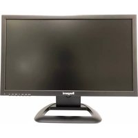


- CAUTION
- WARNING: FOR CONTINUED SAFETY, REPLACE SAFETY CRITICAL COMPONENTS ONLY WITH MANUFACTURE'S RECOMMENDED PARTS (REFER TO SERVICE LITERATURE).
- DECLARATION of CONFORMITY :
- WARNING: TO REDUCE THE RISK OF ELECTRIC SHOCK, DO NOT EXPOSE THIS EQUIPMENT TO RAIN OR WATER.
- Disposal of used Electric and Electronic Equipment
- NOTE:
- CAUTION;
- IMPORTANT SAFETY INSTRUCTIONS
- General
- Power supply
- Usage and location
- Cleaning
- Repair
- PRECAUTIONS FOR OPERATIONS
- Cautions for Rack-Mount.
- Precautions Upon Use
- Avoid operation at low temperatures.
- Caution for condensation.
- Avoid operation or storage in a place exposed to corrosive gas.
- Considerations when storing the monitor in a hard carrying case.
- Quality of LCD panel
- Internal fan
- Warranty
- Accessories
- CONTENTS
- HQLM-1720WR 17-inch 4K/HD Multi Format LCD Monitor
- Outline
- 1-1. Outline
- 1-2. Features
- 4K (3840 x 2160) LCD panel
- Compatible with HDR standard
- Multi-format
- Compatible with 12G-SDI and HDMI 2.0 as the standard equipment
- Compatible with multi-screen display and 2K/HD enlarged display
- Compatibility with embedded audio
- Downmix function
- Function switch
- MENU/UP/DOWN/LEFT/RIGHT SW
- Remote control functions
- Built-in markers and user marker function
- Shadow function
- Various built-in test signals
- Time code display function
- Waveform monitor display functions
- Vector scope display functions
- External memory function
- USB mouse control
- UMD/IMD display with TSL protocol
- UMD/IMD display with user display
- Image & TEST signal MIX function
- Closed caption display
- Switching between HDR and color space by payload
- Names of parts and their Functions
- 2-1. Front Control Panel
- POWER LED
- ⑨ TEST switch
- ⑩ F1 switch
- ⑪ F2 switch
- ⑫ F3 switch
- ⑬ F4 switch
- ⑭ MONO switch
- ⑮ APT switch
- ⑯ SCREEN switch
- ⑰ MARKER switch
- ⑱ CHROMA manual control
- ⑲ BRIGHT manual control
- ⑳ CONT manual control
- ②1 AUDIO control
- ⑫ OVER RANGE indicator
- ②3 Infrared receiver of wireless remote control
- ⑮ USB terminal
- Speakers
- 2-2. Rear panel (left)
- ① AC power input
- ② Lock
- ③ MAIN POWER switch
- ④ Fan1/2
- ⑤ Handle (option)
- ⑥ VESA Mount
- ⑦ Fixed stand (option)
- ◆PRECAUTION
- 2-3. Rear panel (video inputs/outputs)
- ⑤ SDI CH-B4(3G/HD) singal input and output
- Supplementary explanation
- ⑥ Ethernet
- ⑦ HDMI signal input
- ⑧ RS-485 connection
- ⑨ PARALLEL REMOTE signal input
- ⑩ Analog Audio output
- Reference
- a) Cables for 12G-SDI signal
- b) HDMI cable
- Markers
- 3-1. Types of Markers
- MENU Functions
- 4-1. MENU Outline
- 4-2. Description of MENU-INPUT Functions
- ① VIEW MODE setting
- ② 4K MODE VIDEO SOURCE setting
- ③ 4K MODE SDI-A1 SELECT setting
- ④ 4 K MODE SDI-B1 SELECT setting
- ⑤ 4K MODE SDI-B1/2/3/4 SELECT setting
- ⑥ 4K MODE HDMI SELECT setting
- ⑦ 4K MODE IMAGE DIVISION setting
- ⑧ MULTI MODE VIEW MODE setting
- ⑨ MULTI MODE MULTIPATTERN setting
- ⑩ MULTI MODE SYNC MODE setting
- ⑪ MULTI MODE SRC GROUP setting
- ⑫ 2K MODE VIEW MODE setting
- ⑬ 2K MODE VIDEO SOURCE setting
- ⑭ 2K MODE SDI-A1 SELECT setting
- ⑮ 2K MODE SDI-B1 SELECT setting
- ⑯ 2K MODE SDI-B2 SELECT setting
- ⑰ 2K MODE SDI-B3 SELECT setting
- ⑱ 2K MODE SDI-B4 SELECT setting
- ⑲ 2K MODE HDMI SELECT setting
- ⑳ SDI STRUCTURE setting
- Note 1
- Note 2
- ②1 SDI RANGE setting
- ② HDMI (DVI) FORMAT setting
- ②3 INPUT LOCK setting
- ⑳ MIX TEST SIGNAL
- 4-3. Description of MENU-VIDEO Functions
- ① Setting the chroma gain-up ON/OFF
- ② Setting the gain-up level (9db/12dB)
- ③ Setting the scan mode (NORMAL/NATIVE)
- ④ Setting the REAL SCAN ON/OFF
- ⑤ Setting the APERTURE ON/OFF
- ⑥ Setting the APERTURE LEVEL
- ⑦ Setting the APERTURE frequency
- ⑧ Setting the IP conversion mode
- 4-4. Description of MENU AUDIO Functions
- ① Setting the channels of embedded audio for output
- ② Audio selection when the Multiple screen is displayed MULTI SELECT
- ③ Setting the audio level meter display ON/OFF
- ④ Setting the display mode of audio level metering
- HQLM-1720WR
- ⑤ Setting the channel display of the audio level meter
- ⑥ Setting the brightness of the audio level meter
- ⑦ Setting the peak hold display of the audio level meter
- ⑧ Setting the reference level
- ⑨ Downmix setting
- ⑩ Setting the downmix formats
- ⑪ Setting the Ls/Rs level
- ⑫ Setting the embedded audio channel assignment of speaker (Lm)
- ⑬ Setting the embedded audio channel assignment of speaker (Rm)
- 4-5. Description of MENU-TC/WFM/VSC Functions
- 4-6. Description of MENU-MARKER Functions
- ① Setting the type of marker
- ② Setting the safety marker area
- ③ Setting the type of aspect marker
- ④ Setting the safety marker area in aspect marker area
- ⑤ Setting the aspect marker display mode
- ⑥ Setting the aspect marker shadow level
- ⑦ Setting the center marker ON(TYPE-A/B)/OFF
- ⑧ Setting the marker display level
- ⑨ Setting the marker display color
- ⑩ Setting the user marker display ON/OFF
- ⑪ Selecting each scene of user markers and setting the scene names
- ⑫ Setting User Markers
- 4-7. Description of MENU-USER MARKER Functions and Setup
- ① The scene name for user marker
- ② Types of user markers
- ③ Setting the user marker color
- ④ Setting the user marker display ON/OFF
- ⑤ User marker coordinates
- 4-8. Description of MENU-UTILITY Functions
- ① Setting the CONT VR ASSIGN
- ② Setting the CONTRAST RANGE
- ③ Setting the TALLY
- ④ Setting the FORMAT DISPLAY
- ⑤ FRONT LIGHT operation mode
- ⑥ FRONT LIGHT illumination setting
- ⑦ FRONT LED (OVER RANGE) illumination setting
- ⑧ Setting the SYSTEM LOCK
- Shifting to LOCK ALL/PRESET
- ⑨ CONFIG and PASSWORD settings
- CONFIG contents
- PASSWORD setting
- ⑩ Setting the POWER ON CONFIG
- - "POWER ON CONFIG"
- - "SAVE CONFIG"
- - POWER ON ONFIG memory method
- 4-9. Description of MENU-FUNC.SW Functions
- ① Setting the function assignment of the F1 switch
- ② Setting the function assignment of the F2 switch
- ③ Setting the function assignment of the F3 switch
- ④ Setting the function assignment of the F4 switch
- Function switches allocation table
- 4-10. Description of MENU-P.REMOTE Functions
- ① Setting the functions of the parallel remote pins
- ② Setting the user pin function
- ① Setting the TSL/USER DISPLAY function switching
- ② Setting the USER DISPLAY ON/OFF
- ③ Setting the USER DISPLAY character brightness
- ④ Setting the USER DISPLAY character content
- UMD/IMD IndicationTable
- 4-12. Description of MENU-C.CAPTION Functions
- ① Setting of closed caption ON/OFF
- ② Setting of the HD-SDI signal closed caption type
- ③ HD TYPE display subtitle setting
- ④ SD TYPE display subtitle setting
- ⑤ Brightness setting of closed caption
- ⑥ Display size setting of closed caption
- Writing from monitor to USB memory
- ① Setting the date of a file to be written on USB memory
- ② Setting the time of a file to be written on USB memory
- ② -⑥ Writing to USB memory
- File structure
- MENUSW.TXT
- MENU-MARKER.
- ◆Precautions on writing
- Downloading from USB memory to monitor
- ③—⑤ Selecting items to be downloaded
- b) □USER MARKER
- c) □PRESET
- ⑦ Executing the downloading
- ◆Precautions on downloading
- ◆Error messages during writing or downloading
- How to write from monitor to USB memory
- How to download from USB memory to monitor
- Update of firmware
- ⑧ □ MAIN MPU
- ⑨ □ SUB MPU
- ⑩ □ FPGA1
- ⑪ □ FPGA2
- ⑫ □ FPGA3
- ⑬ Updating
- How to update MPU from USB memory
- How to update FPGA from USB memory
- 4-14. Description of MENU-NETWORK Functions
- ① REMOTE number
- ② Setting of the monitor ID number for TSL 4K MODE/2K MODE
- ③ Setting of the monitor ID number for TSL MULTI MODE
- ④ TSL MONITOR ID LT setting
- ⑤ TSL MONITOR ID RT setting
- ⑥ TSL MONITOR ID LB setting
- ⑦ TSL MONITOR ID RB setting
- ⑧ IPV4 SETTING setting
- ⑨ IP ADDRESS setting
- ⑩ SUBNET MASK setting
- ⑪ DEFAULT GATEWAY setting
- ⑫ SPEED / DUPLEX setting
- 4-15. Description of MENU-RESET Functions
- ① Executing the initialization of setup data
- ② Selecting the preset files to be initialized
- 4-16. Description of MENU-INFO Functions (1) INFO (1/2)
- INFO (2/2) - PAYLOAD INFO
- ① VIDEO SOURCE
- ② B1 B2 B3 B4
- ③ Interface ID
- ④ Picture Rate
- ⑤ Sampling Structure
- ⑥ Bit Depth
- ⑦ Transfer Characteristic
- ⑧ Transport Structure
- ⑨ Picture Structure
- ⑩ Colorimetry
- ⑪ Lum & Color Difference
- ⑫ Link Assignment
- ⑬ Aspect Ratio
- ⑭ Horizontal Sampling
- ⑮ Link1 Audio Copy
- Preset Menu Function
- 5-1. List of preset menu
- ① Selection of files
- ② Setting a file change at the time of channel change
- ③ Setting the backlight brightness level
- ④ COLOR SPACE setting
- ⑤ YCbCr MATRIX setting
- ⑥ EOTF setting
- ⑦ TONEMAP setting
- ⑧ HLG VARIABLE setting
- ⑨ HLG CLIP (R/G/B) setting
- ⑩ MASTER CLIP setting
- ⑪ Change of preset data
- - Adjustable
- · BRIGHT (BRIGHTNESS)
- - CONT (CONTRAST)
- • R.BKG (R.BACKGROUND)
- · G.BKG (G.BACKGROUND)
- · B.BKG (B.BACKGROUND)
- • R.GAIN
- • G.GAIN
- • B.GAIN
- ⑫ Copying of file data
- Mouse menu function
- 6-1. Basic procedure of the mouse menu
- Basic behavior of the mouse
- 6-2. Basic procedures on the MENU and PRESET MENU screens
- Specifications
- 7-1. General specifications
- 7-2. Rated performance
- 7-3. Specifications for LCD Panel
- 7-4. Applicable Standerds
- 7-5. Functions
- 7-6. Remote Control
- Mounting
- Options
- External View [UNIT : mm]
- Without option
- Fixed stand STD-1720 with handle GR-1720
- Tilted stand with STD-1720T
- Fixed rack mount with adapter RS-1770
- Tilted fixed rack mount adapter RS-1770T, with a blank panel RS-1770T-BP
- ■ Additional user-set functions
- Data3 RS-485 Pin Functions
- Data4 Control with Remote Controller
- MODEL HQLM-1720WR
- 17-inch 4K/HD Multi Format LCD Monitor
- OPERATION MANUAL
- Ikegami
- Ikegami Tsushinki Co., Ltd.
- Ikegami Electronics (U.S.A.), Inc.
- Ikegami Electronics (Europe) GmbH
- Ikegami Electronics Asia Pacific Pte.LTD.
Brand : Ikegami
Model : HQLM-1720WR
Category : Loudspeaker