
PB3818 - Receiver Pyramid - Free user manual and instructions
Find the device manual for free PB3818 Pyramid in PDF.


| Product Type | Car Stereo Receiver |
| Brand | Pyramid |
| Model | PB3818 |
| Dimensions (W x H x D) | 7 x 2 x 6 inches (approx.) |
| Weight | 2.5 lbs (approx.) |
| Power Supply | 12V DC (negative ground) |
| Maximum Power Output | 50 watts x 4 channels |
| RMS Power Output | 20 watts x 4 channels |
| Frequency Response | 20 Hz - 20 kHz |
| Signal-to-Noise Ratio | > 90 dB |
| Inputs | AUX, USB, SD card |
| Outputs | Speaker outputs (4), RCA preamp outputs (2) |
| Radio Bands | AM/FM |
| Bluetooth | Yes, for hands-free calling and audio streaming |
| Display | LCD with white backlight |
| Remote Control | Included wired remote |
| Mounting | DIN size, single-DIN |
| Additional Features | EQ presets, loudness, fader/balance control |
Frequently Asked Questions - PB3818 Pyramid
User questions about PB3818 Pyramid
0 question about this device. Answer the ones you know or ask your own.
Ask a new question about this device
Download the instructions for your Receiver in PDF format for free! Find your manual PB3818 - Pyramid and take your electronic device back in hand. On this page are published all the documents necessary for the use of your device. PB3818 by Pyramid.
USER MANUAL PB3818 Pyramid
Thank you for purchasing the Pyramid AMERICA High Speed Power Amplifier. The AMPLIFIER has been designed using the latest electronic technology available. The AMPLIFIER is with engineered features allowing you to produce high quality stereo reproduction in mobile applications. This innovative system has been designed A 12 volts DC negative ground power supply. Easy installation with mounting Hardware is provided.
The PB618
utilizes 8 MOSFETS 2 TRANSFORMER inits
design to produce enough voltage to supply the main amplifier and a huge considerable amount of reserve voltage for peak "high demand" situations.


- High level input
- Low level input
3.Input level control -
Fully adjustable high/low pass crossover
-
Bass boost control
6.Low pass control - High pass control
-
Power on LED indicator
-
Protection LED indicator
- Power supply terminals
11.P ower fuse
12.Speaker output terminals
1.HIGH LEVEL INPUT (LOW IMPEDANCE)
If your car stereo does not have RCA output jacks, you can connect the speaker output from the stereo system to the amplifier.
2. LOW LEVEL INPUT (HIGH IMPEDANCE)
This unit is provided with RCA input jacks for High impedance input. Couple the RCA input with the car stereo output using RCA type connector cables.
3.LEVEL CONTROL
Adjusting the control will match the output of the stereo to the amplifier. Turn the control clockwise for more volume and counter-clockwise for less volume if there is distortion when the volume of stereo is turned up, turn the control down.
4.FULL/LPF/HPF CROSSOVER SWITCH
For use with normal full range systems, this selector should be set to the FULL position. If this AMPLIFIER is being utilized to power a CROSSOVER system, this selector should be set to either the HPF(HI PASS FILTER) or LPF(LOW PASS FILTER) position to enable the built-in electronic crossover.
5.BASS BOOST CONTROL
The Bass-Boost dial increases the bass signal to the speaker.
6. LOW PASS CONTROL
The LPF 40Hz/350Hz lets you adjust the crossover frequency from 40Hz to 350Hz, this control is useful only for subwoofers and not you main speakers.
7.HIGH PASS CONTROL
The HPF 80 Hz/2.5KHz lets you adjust the crossover frequency from 80 Hz to 2.5KHz. lets you set the tweeter speakers.
8.POWER ON LED
Lights up when the remote on system is energized.
9.PROTECTION LED
The protection circuitry will disable the amplifier if it senses an input overload, speaker short circuit of extreme high temperature conditions. When the protection circuit is in operation the LED indicator on the unit will light indicating that the amplifier has gone into a self preservation mode. At this time please check your system to see what is causing the protection circuit to fire. The amplifier can be reset by turning the remote power off and then on again. If the system shuts down because of a thermal overload condition, allow the amplifier to cool down before restarting. If the amplifier shutdown because of an input overload or speaker short circuit please be sure to correct these conditions before restarting the amplifier.
10. POWER SUPPLY
A. +12V
To connect +12V DC power supply wire from the terminal of battery.
B. GROUND
To connect the ground wire from the chassis of the automobile.
C. REMOTE
To connect the control wire which provides remote turn on and off of the amplifier by the radio/cassette player. (Usually The Auto Antenna Lead)
11. POWER FUSE
The power fuse protects both this amplifier and the automobile electrical system from short circuit conditions.
12.SPEAKER TERMINALS.
The speaker terminals are for high conductivity and minimum impedance loss. The terminals are facing upwards for easy wiring in tight situations. Be sure to strip just enough insulation off your speaker wires that will fit under the screw plate to help ensure against speaker wire short circuits.
13. TRI-MODE BRIDGING CAPABILTY.
The Amplifier can be bridged into the following systems.
A. three channel Mode. Bridge Channels 3 & 4 into one high power channel for subwoofer application while leaving channels 1 & 2 in the stereo mode for satellite components.
B. Two Channel Mode. Bridge channels 1 & 2 into one high powered channel. Bridge channels 3 & 4 into a second high powered channel. Be sure to utilize speaker which can handle at rated power on the bridged channels.
14.MUTE TURN ON CIRCUIT
The Amplifier features an anti-thump delay circuit. This circuit eliminates irritating thump noise some times experienced with cheaper amplifiers when they are turned on.
A. STEREO INPUT CONNECTION
• NOTE: Do not use both low and high level inputs simultaneously! RCA TYPE TERMINAL
This amplifier is provided with gold plated RCA terminals for LOW LEVEL INPUT to match radios and equalizers with line level output.(Fig. 1A) If you STEREO has only RIGHT and LEFT outputs then you must use a Y-adaptor connecting the stereo to the amplifier as indicated. (Fig. 1B)
WHEN YOU WANT TO BRIDGE THE AMPLIFIER PLEASE COMPLET THE FOLLOWING STEPS.
- If your STEREO only use RIGHT and LEFT outputs, please wire as (Fig. 2A)
- If your STEREO has four channel outputs please wire as (Fig. 2B).
NOTE: Do not use both low and high level inputs simultaneously!

(Fig. 1A)
(PB6 18)

(Fig. 1 B)

(Fig. 2A)
(PB6 18)

B. SPEAKER CONNECTIONS
You do not need to make any adjustment for the input connection of Amplifier before you connect the speaker output.
1. 4 Channel Output Mode
Connect the speaker output terminals to the corresponding speaker. (Fig. 3A)

(Fig.3A)
(PB6 18)
2. 2 Channel Output Mode
You may want to bridge the Amplifier to a 2 CHANNEL output amplifier. use high quality speakers which are capable of handling the high power output. In this mode only the 1-2CH and 3-4CH speaker will be activated. (Fig. 3B)

(Fig.3B)
C.2-CHANNEL STEREO OUTPUT COMBINED WITH MONO SUBWOOFER OUTPUT MODE
(a)SUBWOOFER
Connect the speaker to the 3-4CH speaker terminal.
(b) 2-CHANNEL STEREO
The RIGHT signal output from 2-RIGHT speaker terminal.
The LEFT signal output from 1-LEFT speaker terminal.


- High level input
2.Low level input
3.Aux line output
4.Input level control - Bass boost control
6.Low pass control -
High pass control
-
Fully adjustable high/low pass crossover
-
Power on LED indicator
-
Protection LED indicator
-
Power supply terminals
12.Power fuse
13.Speaker output terminals
1. HIGH LEVEL INPUT(LOW IMPEDANCE)
If your car stereo does not have RCA output jacks, you can connect the speaker output from the stereo system to the amplifier.
2. LOW LEVEL INPUT(HIGH IMPEDANCE)
This unit is provided with RCA input jacks for High impedance input. Couple the RCA input with the car stereo output using RCA type connector cables.
3. AUX LINE OUTOUT
This amp features RCA jacks or AUX line output.
4. INPUT LEVEL CONTROL
Adjusting the control will match the output of the stereo to the amplifier. Turn the control clockwise for more volume and counter-clockwise for less volume if there is distortion when the volume of stereo is turned up, turn the control down.
5. BASS BOOST CONTROL
The Bass-Boost dial increases the bass signal to the speaker.
6. LOW PASS CONTROL
The LPF 50Hz/250Hz lets you adjust the crossover frequency from 50Hz to 250Hz, this control is useful only for subwoofers and not you main speakers.
7. HIGH PASS CONTROL
The HPF 120Hz/3kHz lets you adjust the crossover frequency from 120Hz to 3kHz, lets you set the tweeter speakers.
8. FULL/LPF/HPF CROSSOVER SWITCH
For use with normal full range systems, this selector should be set to the FULL position. If this AMPLIFIER is being utilized to power a CROSSOVER system, this selector should be set to either the HPF (HIGH PASS FILTER) or LPF (LOW PASS FILTER) position to enable the built-in electronic crossover.
9. POWER ON LED
Lights up when the remote on system is energized.
10. PROTECTION LED
The protection circuitry will disable the amplifier if it senses an input overload, speaker short circuit of extreme high temperature conditions. When the protection circuit is in operation the LED indicator on the unit will light indicating that the amplifier has gone into a self preservation mode. At this time please check your system to see what is causing the protection circuit to fire. The amplifier can be reset by turning the remote power off and then on again. If the system shuts down because of a thermal overload condition, allow the amplifier to cool down, before restarting. If the amplifier shutdown because of an input overload or speaker short circuit please be sure to correct these conditions before restarting the amplifier.
11. POWER SUPPLY
A.+12V
To connect +12V DC power supply wire from the terminal of battery.
B. GROUND
To connect the ground wire from the chassis of the automobile.
C. REMOTE
To connect the control wire which provides remote turn on and off of the amplifier by the radio/cassette player. (Usually The Auto Antenna Lead)
12. POWER FUSE
The power fuse protects both this amplifier and the automobile electrical system from short circuit conditions.
13. SPEAKER OUTPUT TERMINALS
The speaker terminals are for high conductivity and minimum impedance loss. The terminals are facing upwards for easy wiring in tight situations. Be sure to strip just enough insulation off your speaker wires that will fit under the screw plate to help ensure against speaker wire short circuits.
(PB718/PB918/PB2518/PB3818)

STEREO MODE

MONO MODE
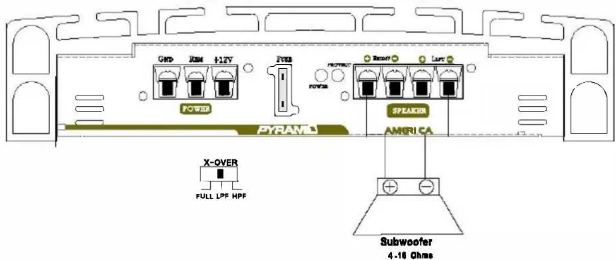
D.POWER CONNECTION
- Connect the B +12V pole of power supply directly to the battery (+)position terminal.
- Connect the GND pole of power supply directly to the (-) negative ground battery terminal or car chassis.
- To make a good grounding and prevent motor boating noise problem connect another 12 gauge minimum wire from the (-) negative battery terminal to chassis of stereo unit.
- Connect the 'Remote' pole to external switch for positive 12V ON/OFF. This may be connected to the receiver power antenna lead.

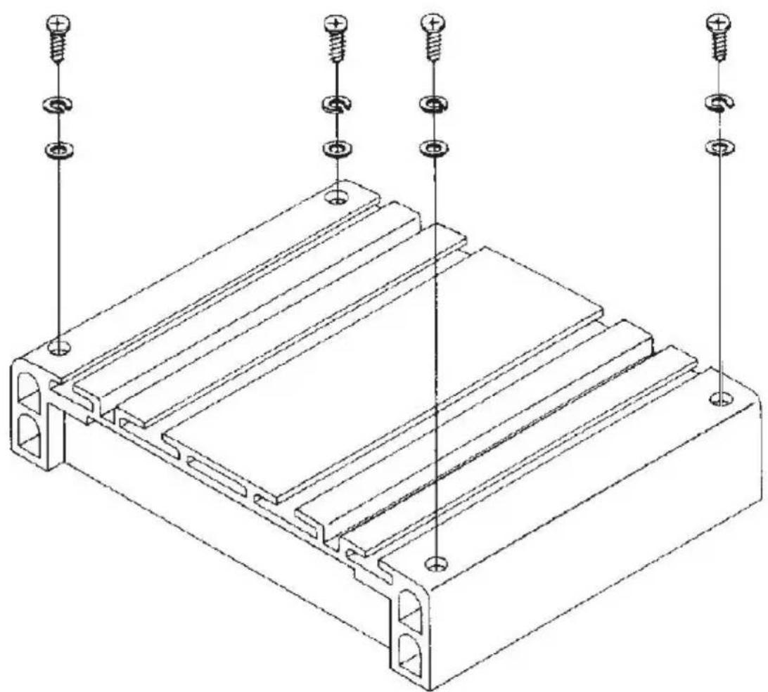
The Amplifier comes complete with all mounting hardware, While the Amplifier can be mounted in any convenient location in your vehicle, please remember that this is a high power unit which generates high electrical energy and heat. Therefore be sure to install the unit in a place with sufficient airflow, a minimum of dust and no moisture. Allow enough space around the cooling fins to permit reasonable airflow and cooling.
Choose a suitable location to mount the amplifier so that it is protected from vibration.
Check clearance all around the amplifier be sure to leave enough room for wiring.
Secure the amplifier tightly. Do not leave an unmounted amplifier in your car trunk or deck as it can be a driving hazard should you be forced to make a short stop.
natural_image
Technical line drawing of a mechanical component with multiple screw holes and mounting holes (no text or symbols)-
After all the connections have been made, turn on your stereo and listen for the amplifier to turn on. If there are any unusual noises from the speakers then turn the system off and recheck all wiring.
-
After you have connected your radio or requalizer to the amplifier, you may adjust the gain control to match the output level of your radio.
(A) Set the volume control on you radio to 2/3 position
(B) Adjust the gain control for an average listening level.
(C) Turn the radio volume all the way down and listen for background noise.
(D) Start your vehicle and listen for electrical noise.
(E) Making fine adjustments to the sensitivity can reduce background noise and Some engine noise.
(F) CAUTION: Never turn the sensitivity up any farther than you need to get clear sound at 2/3 volume.
(G) This adjustment only needs to be made once.
SPECIFICATIONS
- Output Power @ 14.4VDC 1KHZ
RMS power @4 ohms RMS power @2 ohms RMS power @1 ohms MAX power Output
| PB618: 50W x 4 | 100W x 4 | 2000W |
| PB718: 35W x 2 | 70W x 2 | 1000W |
| PB918: 50W x 2 | 100W x 2 | 2000W |
| Pb2518: 75W x 2 | 150W x 2 | 3000W |
| Pb3818: 100W x 2 | 200W x 2 | 5000W |
PB618=200W x 2 or 2000W x 2 and 200W x 1
- Bridged Mode....PB718=150W x 2 of 1000W x 2 and 200W x 1
PB918 = 200Wx2 or 2000Wx2 and 200Wx1
PB2518=300W x2 or 3000W x2 and 300W x1
PB3818=500W x2 or 5000W x 2 and 500Wx1
-
Frequency Response....10-30,000 Hz (±3 dB)
-
Input Impedance 10K Ohms (Low Level) 100 Ohms (High Level)
-
Input Sensitivity....250mV (Low Level) 2.5V (High Level)
-
Power Supply Voltage....., DC 14.4V Negative Ground 10.5-16V)
-
Matching Speaker Impedance.... Stereo Mode: 2-4 Ohms Bridged Mode: 4-8 Ohms
-
Maximum Current Draw....PB618=20A x 2 PB718=25A x1 PB918=30A x 1 PB2518=35A x1 PB3818=30A x 2
-
Dimensions.... PB618=260 x 57.5 x 350mm (W x H x L) PB718=260 x 57.5 x 12mm (W x H x L) PB918=260 x 57.5 x 230mm (W x H x L) Pb2518=260 x 57.5 x 280mm(W x H x L) Pb3818=260 x 57.5 x 350mm (W x H x L)
-
Net Weight....PB618 3.9kg PB718 2.496kg PB918 2.654kg PB2518 3.264kg PB3818 3.962kg

INVERSIONES PYRAMIDCARAUDIO C.A
RIF : J-31213319-8
www.pyramidcaraudio.com
e ma l : pyramidearaudio@gmail.com


- 1.HIGH LEVEL INPUT (LOW IMPEDANCE)
- LOW LEVEL INPUT (HIGH IMPEDANCE)
- 3.LEVEL CONTROL
- 4.FULL/LPF/HPF CROSSOVER SWITCH
- 5.BASS BOOST CONTROL
- LOW PASS CONTROL
- 7.HIGH PASS CONTROL
- 8.POWER ON LED
- 9.PROTECTION LED
- POWER SUPPLY
- POWER FUSE
- 12.SPEAKER TERMINALS.
- TRI-MODE BRIDGING CAPABILTY.
- 14.MUTE TURN ON CIRCUIT
- STEREO INPUT CONNECTION
- SPEAKER CONNECTIONS
- 4 Channel Output Mode
- (PB6 18)
- 2 Channel Output Mode
- C.2-CHANNEL STEREO OUTPUT COMBINED WITH MONO SUBWOOFER OUTPUT MODE
- HIGH LEVEL INPUT(LOW IMPEDANCE)
- LOW LEVEL INPUT(HIGH IMPEDANCE)
- AUX LINE OUTOUT
- INPUT LEVEL CONTROL
- BASS BOOST CONTROL
- HIGH PASS CONTROL
- FULL/LPF/HPF CROSSOVER SWITCH
- POWER ON LED
- PROTECTION LED
- POWER SUPPLY
- POWER FUSE
- SPEAKER OUTPUT TERMINALS
- D.POWER CONNECTION
- SPECIFICATIONS
Brand : Pyramid
Model : PB3818
Category : Receiver