
PUB2 300 - Heat pump Nibe - Free user manual and instructions
Find the device manual for free PUB2 300 Nibe in PDF.


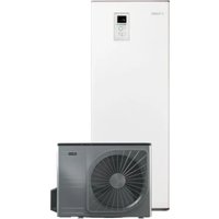
| Product Type | Air-to-water heat pump |
| Brand | Nibe |
| Model | PUB2 300 |
| Dimensions (H x W x D) | Approx. 600 x 600 x 800 mm |
| Weight | Approx. 80 kg |
| Power Supply | 230 V, single phase, 50 Hz |
| Heating Capacity | Up to 10 kW (depending on conditions) |
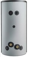
| Hot Water Capacity | Integrated 300 L tank (model PUB2 300) |
| Refrigerant | R410A (check manual for exact type) |
| Energy Efficiency Class | A++ (typical) |
| Functions | Heating, cooling, domestic hot water production |
| Control | Digital display and remote control |
| Installation | Indoor unit with separate outdoor unit (split system) |
| Noise Level | ~30 dB (indoor unit) |
| Maintenance | Regular cleaning of air filter; annual professional check |
| Safety Features | Overheat protection, freeze protection, pressure relief valve |
| Spare Parts Availability | Available through Nibe authorized service centers |
| Warranty | 2 years (standard, may vary by region) |
Frequently Asked Questions - PUB2 300 Nibe
User questions about PUB2 300 Nibe
0 question about this device. Answer the ones you know or ask your own.
Ask a new question about this device
Download the instructions for your Heat pump in PDF format for free! Find your manual PUB2 300 - Nibe and take your electronic device back in hand. On this page are published all the documents necessary for the use of your device. PUB2 300 by Nibe.
USER MANUAL PUB2 300 Nibe
PUB2/PUB2 DS 160-500
EN User and Installer Manual - Accumulator tank
natural_image
Three large cylindrical industrial tanks with black bases and metallic caps, no visible text or symbols.
natural_image
Pure electrical circuit lines without any symbolsTable of Contents
Svenska
4Viktig information
6Till användaren
7Till installatören
The serial number can be found on top of the pro
SAFETY INFORMATION
This manual describes installation and service ures for implementation by specialists.
The manual must be left with the customer.

Caution
proced- You need the product's (14 digit) serial number for servicing and support.
RECOVERY
This appliance can be used by chil aged from 8 years and above and with reduced physical, sensory or m
Leave the disposal of the packaging to the ir staller who installed the product or to special mental waste stations.
capabilities or lack of experience and

Do not dispose of used products with normal
knowledge if they have been given vision or instruction concerning use appliance in a safe way and unde
superhousehold waste. It must be disposed of at a spec the waste station or dealer who provides this type of service.
the hazards involved. Children shall play with the appliance. Cleaning a maintenance shall not be made by without supervision.
not proper disposal of the product by the user results administrative penalties in accordance with current legislation children
Rights to make any design or technical modi cations are reserved.
©NIBE 2019.
SYMBOLS

NOTE
This symbol indicates danger to person or machine.

Caution
This symbol indicates important information about what you should consider when installing or servicing the installation.
GENERAL
PUB2/PUB2 DS 160-500 is designed and manufactured according to good technical practice order to ensure safe usage.
INSPECTION OF THE INSTALLATION
Current regulations require the heating installation to be inspected before it is commissioned. The ins be carried out by a suitably qualified person.
| DateSignat | ||||
| Hot water (page 23) | ||||
| Shut off valves | ||||
| Cold water (page 23) | ||||
| Shut off valves | ||||
| Non-return valve | ||||
| Safety valve | ||||
| Vacuum valve | ||||
| Mixing valve | ||||
For the User
MAINTENANCE
SAFETY VALVE (NOT SUPPLIED)
The water heater's safety valve sometimes releases a little water after hot water usage. This is because the cold water, which enters the water heater, expands when heated causing the pressure to rise and the safety valve to open.
The function of the safety valves must be regularly checked, about four times a year, to prevent clogging.
To inspect the valve, open the safety valve manually and check that water is owing through the over ow pipe. If this is not happening, the safety valve is defective and must be replaced.
EMPTYING
- Close the incoming ow to the charge coil.
- Shut off the incoming cold water.
- Loosen the cover of the drain valve and install a suitable hose.
- Open the drain valve.
During draining, air must be let into the water heater by loosening a hot water connector (XL4) or opening a hot water tap.
To ensure that the water heater drains completely, a hose or a pipe with an outlet below the lowest level of the water heater must be attached to the drain connection or drain valve. When installed in a location that is exposed to the risk of frost, the water heater must be emptied whenever it is not in operation. Freezing could result in the water heater bursting.
SERVICE
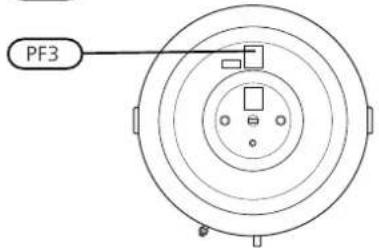
For service, contact the installer. Serial number (PF3) (14 digits) and installation date should always be stated. Only replacement parts supplied by NIBE may be used.
For the Installer
GENERAL
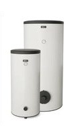
PUB2/PUB2 DS 160-500 is a series of accur tanks/water heaters, suitable for connection to oil boilers.
The water tank consists of a steel jacket, lining to protect against corrosion. PUB2/PUB2500 is equipped with two copper coils.
PUB2/PUB2 DS 160-500 is designed and man for a maximum cut-off pressure of 10 bar. permitted temperature is 90 °C.
The max. working pressure in the coil is 20 max. working temperature in the coil is 120
On 500 L containers, the insulation is made of Neopor and polyester eece, which provides excellent heat insulation. The insulation and the grey plastic outer cladding can easily be removed to simplify moving the product, for example through doorways.
On the other vessel sizes, the insulation is polyurethane, which provides excellent heat insulation. The outer shell is grey plastic.
PUB2/PUB2 DS 160-500 is equipped with submerged tube for control of hot water heating. Cover discs
TRANSPORT
PUB2/PUB2 DS 160-500 should be transported and stored vertically in a dry place. The PUB2/PUB2 DS 160-500 may, however, be carefully laid on its back when being moved into a building.
ASSEMBLY
PUB2/PUB2 DS 160-500 must only be installed vertically
PUB2/PUB2 DS 160-500 is unscrewed from the pallet and lifted into position. (use the lifting eye on the date PUB2 DS 500).
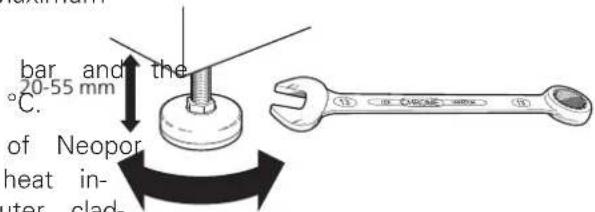
gas or Position PUB2/PUB2 DS 160-500 on a rm base that can take the weight, preferably on a concrete oor th a copper foundation. Use the product's adjustable feet to obtain DS 160- a horizontal and stable set-up.
The area where the PUB2/PUB2 DS 160-500 is located must be frost-proof and equipped with a oor drain.
SUPPLIED COMPONENTS


Insulation plug

COMPONENT POSITIONS


PUB2 500PUB2 160 - 300

| NameDesignation | |
| Vacuum valve (not included in delivery)FL6 | |
| Safety valve (not included in delivery)FL10 | |
| Mixer valve (not included in delivery)FQ1 | |
| Tapping valveQM4 | |
| Shut-off valve (not included in delivery)QM40 | |
| Non-return valve (not included in delivery)RM1 | |
| Submerged tube, docking heat pump BT6, ∅ 11 mm (int)UA1 | |
| Adjustable feetUL1 | |
| Lifting eyeXR1 | |
| Serial number platePF3 |
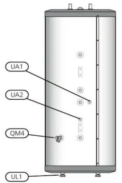


| NameDesignation | |
| Tapping valveQM4 | |
| Submerged tube, docking heat pump BT6, ∅ 11 mm (int)UA1 | |
| Submerged tube, external heat source, solar, ∅ 11 mm (int)UA2 | |
| Adjustable feetUL1 | |
| Lifting eyeXR1 | |
| Serial number platePF3 |
REMOVING THE INSULATION
The insulation on PUB2 DS 500 can be removed to facilitate work in con ned spaces.
- Unscrew the lifting eye at the top.
- Lift off the plastic top and the top insulation.
- Remove the joining plates holding the insulated jacket halves together. Do not use any tools when dismantling.
- Unhook and remove the halves of the insulated jacket; the outer diameter is approx. 200 mm less without the insulated jackets.
The gure shows PUB2 DS 500 with
Insulation removedDo not use any tool
insulation
ling the joining plate.

natural_image
Diagram of a cylindrical device with internal components and an upward arrow, no text or symbols present
natural_image
Illustration of a hand holding a rectangular object with a curved line above, showing a motion arrow (no text or symbols)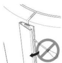
natural_image
Simple line drawing of a vertical structure with a diagonal line and a circular symbol below (no text or labels)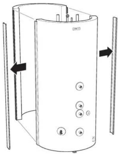
natural_image
Diagram of a cylindrical device with multiple circular buttons and directional arrows indicating flow or movement (no text or symbols present)
natural_image
Abstract line drawing of layered building structures with arrows indicating direction (no text or symbols)Carry out assembly in reverse order.
Install the enclosed insulation plugs around each connection, and in the hole for the lifting eye. Finally, t all the enclosed cover discs on each connection by pressing them over the connections.
In certain cases, more insulation plugs are enclosed than are required.

Caution
Fit the cover discs and the insulation plugs before installing the pipe.

Caution
Fit the enclosed cover discs before pipe. This installable equivalent to a water ow of approx. 1650 atation. The cover discs, with self-adhesive a ∅22 mm charge coil (PUB2/PUB2 DS 160-500). Backs, must be installed on the relevant connection. The supply temperature to the charge coil must not be connected by pushing them over the connections. 120 °C and the operating temperature in All connections (including connections or HUB2/PUB2 DS 160-500 must not exceed 90 °C. left by the lifting eyes that are not used) must be insulated to minimise energy losses. The risk of air bubbles in the charge coil is eliminated because the intake connection is the highest point.
When determining the water speed, 1.5 m/s should be exceeded in the event of continuous charge ow.
PRESSURE DROP DIAGRAM
PIPE INSTALLATION
Pipe installation must be carried out in accordance with current norms and directives. Pressure dro

NOTE
PUB2/PUB2 DS 160-500 must be lled water before commencing charging via charge coil.
PUB2/PUB2 DS 160-500 must be tted with ite valves, such as a safety valves, shut-off return valves and vacuum valves.
PUB2/PUB2 DS 160-500 must be supplied with a mixing valve, which limits the temperature of outgoing hot water to 60 °C. If this valve is not tted, some other measure must be taken to prevent the risk of building/PUB 5001
An internal support bush must be tted when a plastic or annealed copper pipe is used. An over ow pipe must be routed from the safety valve to a suitable drain. The overflow pipe must be the same size as the safety valve. Route the over ow pipe from the safety valve, sloping along its entire length, and ensure that it is frost-proof and well supported. The mouth of the over ow pipe must be visible and not placed close to electrical components.
Ensure that incoming water is clean. When using a private well, it may be necessary to supplement with an extra water liter.
If uncertain, contact a plumber alternatively see applicable standards.
FILLING
Fill the water heater as follows:
- Open a hot water tap in the system.
- Open the shut-off valve for the incoming cold water. Afterwards, this valve must be fully open during operation.
- The hot water tap can only be shut off when the water heater is lled, which is when only water comes out of the tap (initially an air-water mixture comes out of the tap).
Primary side (coil)

line
| Flow (l/h) | Pressure drop over coil (kPa) - Curve 1 | Pressure drop over coil (kPa) - Curve 2 | Pressure drop over coil (kPa) - Curve 3 | | ---------- | ---------------------------------------- | ---------------------------------------- | ---------------------------------------- | | 0 | 0 | 0 | 0 | | 200 | ~2 | ~1 | ~0.5 | | 400 | ~6 | ~3 | ~1.5 | | 600 | ~12 | ~6 | ~3 | | 800 | ~18 | ~10 | ~5 | | 1000 | ~24 | ~14 | ~7 | | 1200 | ~30 | ~18 | ~9 | | 1400 | ~36 | ~22 | ~11 | | 1600 | ~42 | ~26 | ~13 |Technical data
DIMENSIONS
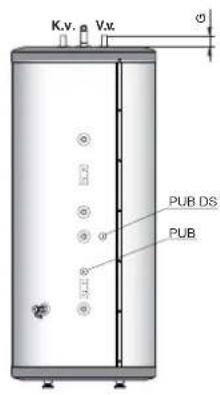
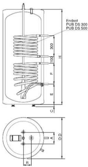
PUB2 DS 500PUB2 DS 160-300

PUB2 500
| PUB2 | DSPUB2 | ||||
| 3001603 | |||||
| 1701701 | |||||
| 1151151 | |||||
| 30-6530-6 | |||||
| 6006006 | |||||
| 3002653 | |||||
| 3003606 | |||||
| G | 45 | 45 | 50 | 45 | 50 |
| H | 980 | 1210 | 1380 | 980 | 1380 |
Approx. dimensions in mm
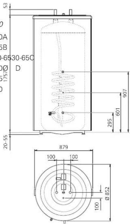

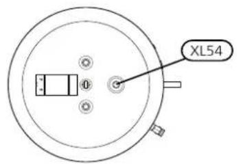
PUB2 500PUB2 160-300


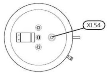
PUB2 DS 500PUB2 DS 160-300
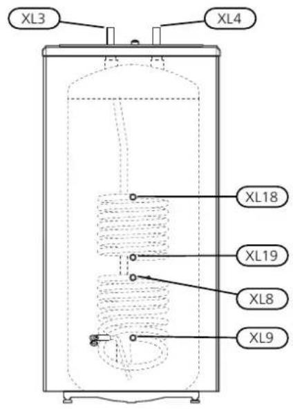

| PUB2 500PUB2 160-30 | |||
| ∅ 35 mm∅ 22 mm∅ | |||
| ∅ 35 mm∅ 22 mmH | |||
| ∅ 22 mmDocking connection, | |||
| ∅ 22 mmDocking connection, | |||
| ∅ 22 mmDocking connection, | |||
| ∅ 22 mmDocking connection, | |||
| XL54 | Connection for thermometer or hot water circulation | G 12 | |
*Only PUB2 DS 300 and PUB2 DS 500
TECHNICAL SPECIFICATIONS
| PUB2 DSPUB2 | ||||||||
| 5003001605003002 | ||||||||
| 1 | CCBCCBBEf cienc | |||||||
| 8526006008526006 | ||||||||
| insulation ∅ | 668—668—mmDia | |||||||
| 17571380980175713 | ||||||||
| 19701525401701900 | ||||||||
| Net weight | kg | 56 | 68 | 73 | 140 | 63 | 100 | 158 |
| Max pressure, water heater | bar/MPa | 10/1,0 | ||||||
| Max. pressure, charge coil | bar/MPa | 20/2,0 | ||||||
| Max. working temperature in water heater | theC | 90 | ||||||
| Max. working temperature in coil | theC | 120 | ||||||
| Length, coil | m | 4,25 | 4,25 | 6,3 | 6,3 | 7,4 | 2x7,4 | 2x7,4 |
| Heating surface, coil | m^2 | 1,4 | 1,4 | 1,9 | 1,9 | 1,8 | 2x1,8 | 2x1,8 |
| Primary ow | l/h | 1200 | 1200 | 1300 | 1300 | 100 | 2x1000 | 2x1000 |
| 80/10-45°C2 | Continuous hot water | 1504150600880880 | ||||||
| Heat transfer 80/10-45°C2 | kW | 26 | 29 | 39 | 39 | 24 | 47 | 47 |
| Heating time 80/10 - 60°C3 | min. | 28 | 35 | 35 | 62 | |||
| Corrosion protection | Copper | |||||||
| Part No. | 087 400 | 087 410 | 087 420 | 081 086 | 087 440 | 087 460 | 081 087 | |
^1 Scale for the product's efficiency class A+ to F.
^2 The capacity refers to use for continuous hot water, where the accumulated amount of hot water is not included.
^3 The values apply at a primary ow of 1000 l/h
ENERGY LABELLING
| Supplier | NIBE | |||||||
| Model | PUB2 160 | PUB2 210 | PUB2 300 | PUB2 500 | PUB2 DS 160 | PUB2 DS 300 | PUB2 DS 500 | |
| Energy efficiency class | B | B | C | C | B | C | C | |
| Heat loss | W | 53 | 62 | 92 | 111 | 53 | 92 | 111 |
| Volume | I | 160 | 210 | 270 | 500 | 160 | 270 | 500 |
Nederlands
This manual is a publication from NIBE Energy Systems. All product illustrations speci cations are based on current information at the time of the publication's NIBE Energy Systems makes reservations for any factual or printing errors in

- PUB2/PUB2 DS 160-500
- Table of Contents
- SAFETY INFORMATION
- Caution
- RECOVERY
- SYMBOLS
- NOTE
- GENERAL
- INSPECTION OF THE INSTALLATION
- For the User
- MAINTENANCE
- SAFETY VALVE (NOT SUPPLIED)
- EMPTYING
- SERVICE
- For the Installer
- TRANSPORT
- ASSEMBLY
- SUPPLIED COMPONENTS
- COMPONENT POSITIONS
- REMOVING THE INSULATION
- PRESSURE DROP DIAGRAM
- PIPE INSTALLATION
- FILLING
- Technical data
- DIMENSIONS
- Nederlands
Brand : Nibe
Model : PUB2 300
Category : Heat pump