
ITCFD05B - Uncategorized Scosche - Free user manual and instructions
Find the device manual for free ITCFD05B Scosche in PDF.


| Type of Product | Car Charger |
| Dimensions | 2.5 x 1.5 x 0.8 inches |
| Weight | 1.2 oz |
| Input Voltage | 12-24V DC |
| Output Voltage | 5V DC |
| Output Current | 2.4A per port |
| Number of USB Ports | 2 |
| Charging Technology | Fast charging (compatible with QC 3.0) |
| Power Source | Cigarette lighter socket |
| Overcurrent Protection | Yes |
| Short Circuit Protection | Yes |
| Overheat Protection | Yes |
| Material | ABS plastic, metal contacts |
| LED Indicator | Yes (blue LED) |
| Compatible Devices | Smartphones, tablets, GPS, dash cams |
| Operating Temperature | -20°C to 60°C |
| Storage Temperature | -30°C to 70°C |
| Certification | CE, RoHS, FCC |
| Warranty | 2 years limited |
| What's in the Box | Car charger, user manual |
Frequently Asked Questions - ITCFD05B Scosche
User questions about ITCFD05B Scosche
0 question about this device. Answer the ones you know or ask your own.
Ask a new question about this device
Download the instructions for your Uncategorized in PDF format for free! Find your manual ITCFD05B - Scosche and take your electronic device back in hand. On this page are published all the documents necessary for the use of your device. ITCFD05B by Scosche.
USER MANUAL ITCFD05B Scosche
IN-DASH INSTALLATION KIT FOR
2015-UP FORD MUSTANG
SINGLE ZONE MANUAL CLIMATE CONTROLS
**Dash Modification Required**
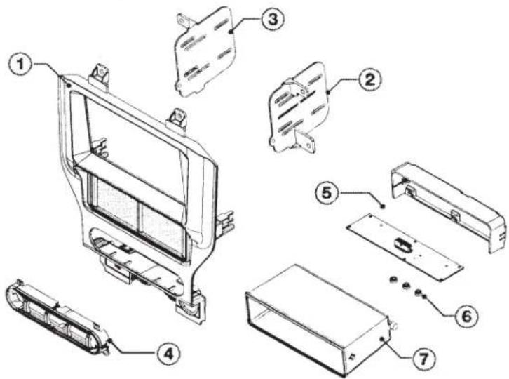
Kit Content
- Face Panel *w/ UAC 7773
- Right Bracket 7774
- Left Bracket 7775
- Three Button Swtch Trim 7776
- Back Cover 7778
- PCB Spacer 77799
- Pocket 6761
Instruction Index PG
Radio Disassembly 2-3
Dash Modification.... 3
Panel Preparation.... 6
Radio Installation.... 6
Steering Wheel Controls/Diagram..... 7
UAC Wiring Diagram.... 8
Left Screen Functionality....10-11
Right Screen Functionality.... 11
Menu Navigation.... 12
Vehicle/Installer Menu Chart 13
ITC/Language Chart.... 14
Notes 15-16
Tools Required
• PRT (Panel Removal Tool)
- Screwdriver
- Rotary Cutting Tool
- Filing Tool
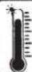
NOTICE:
Extremely high temperatures may temporarily affect the display. Normal operation will resume once the unit cools.
INTRODUCTION / PRELIMINARY
This premium installation kit is for 2015-UP Ford Mustang vehicles with single zone manual climate controls (dash modification required). Included are all the parts you need to mount your car stereo or CD player into your vehicle's dash. Refer to individual instruction in this manual to remove your vehicles factory radio and assemble the kit.
CAUTION: DISCONNECT YOUR VEHICLE NEGATIVE BATTERY TERMINAL BEFORE THE INSTALLATION TO HELP PREVENT ELECTRICAL DAMAGE. WE RECOMMEND THE USE OF A VOLT/OHM METER OVER A TEST LIGHT TO CHECK WIRING. A TEST LIGHT OR GROUNDED WIRE PROBE CAN CAUSE DAMAGE TO THE VEHICLE'S COMPUTER AND/OR DIAGNOSTIC SYSTEMS. AVOID ALL FACTORY AIRBAG WIRING - AIRBAGS CAN ACCIDENTALLY DEPLOY CAUSING SERIOUS INJURY OR DEATH.
NOTES
- See your vehicle's instructions for any special tools your installation might require.
- Read all instructions accompanying your car stereo for proper wiring and mounting instructions.
STOP
IMPORTANT!
DO NOT RETURN PRODUCT TO THE RETAILER
IF YOU NEED ASSISTANCE OR REPLACEMENT PARTS CALL US TOLL FREE: 1800-621-3695 X3
HOURS: MON-FRI 8AM-5:30PM (PST) SATURDAY 8AM-2PM (PST)
LIABILITY DISCLAIMER
This instruction booklet is based on carefully documented data and research of automobile disassembly, wire harness/codes and information pertaining to the installation of this kit. Scosche Industries, Inc. cannot be held responsible for discrepancies/inconsistencies that may occur due to the automobile manufacturing changes or options, or damages that may occur in the automobile during the installation of components while using this booklet.
If you have any questions, call our toll free technical help line at:
1-800-621-3695 x3
INSTALLATION GUIDE
Radio Disassembly
Step 1
Radio Disassembly
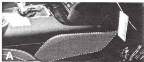
Image A:
Remove the two (passenger and driver side) knee panels on the lower console.
natural_image
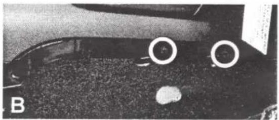
Close-up of fabric pieces with a dotted patterned edge, no visible text or symbolsImage B:
Next remove two exposed screws.
natural_image
Close-up of a dark textured surface with two white circular markers and label 'B' (no readable text or symbols)Step 2
Radio Disassembly
Image A:
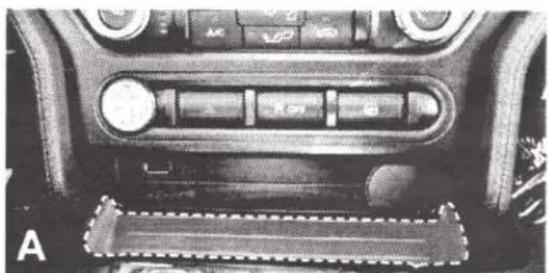
Using a PRT (Panel Removal Tool) Carefully remove the tray located below the USB and 12v socket ports, then remove and retain two screws exposed.
natural_image
Interior view of a car dashboard with control buttons and a textured panel (no visible text or symbols)Image B:
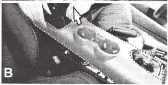
Lift and slightly pullback the center cup holder console but do not remove.
natural_image
Close-up of a mechanical component with no visible text or symbolsStep 3
Radio Disassembly
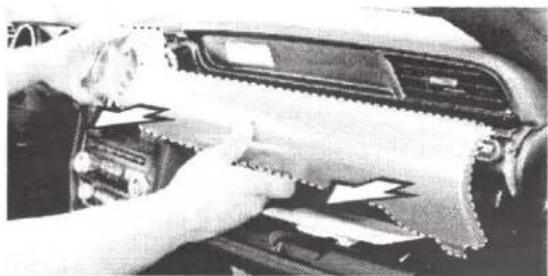
Using PRT (Panel Removal Tool) carefully remove the air-vent trim surrounding the vents, temp, and boost control gauge; unplug and remove.
natural_image
Close-up of hands cleaning a car interior with visible tire and door panel (no text or symbols)Step 4
Radio Disassembly
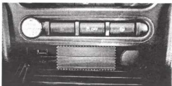
Unclip and remove the plastic plate located in-between the USB plug-in and the cigarette lighter.
natural_image
Close-up of a mechanical component with a cylindrical shaft and circular head (no visible text or symbols)INSTALLATION GUIDE
Radio Disassembly
Step 5
Radio Disassembly
Remove the four screws securing the OEM panel to the dash; then unplug and remove the panel (See image on right side).
natural_image
Interior view of a device housing with mounting holes and a central display (no visible text or symbols)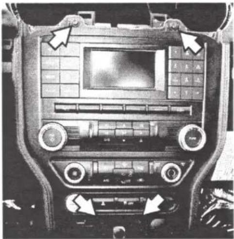
natural_image
Interior view of a car dashboard with digital display and control knobs (no visible text or symbols)Step 6
Radio Disassembly
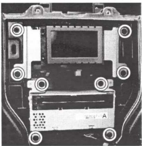
Remove the OEM Display and the CD receiver by unscrewing the four screws for each component (8 screws total, circled); then unplug all wiring and remove (See image on the left).
INSTALLATION GUIDE
Dash Modification
CAUTION
Major modifications required for double DIN installation. Proceed with CAUTION!

Step 7
Dash Modification
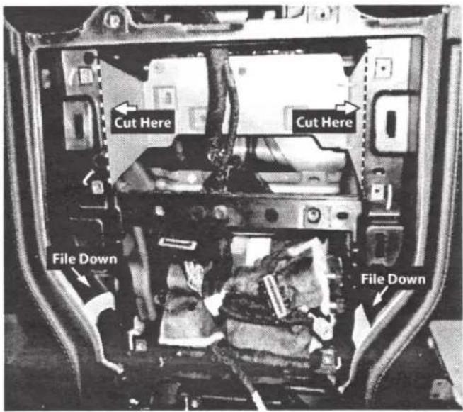
Carefully cut and remove the highlighted dashed area on the sub-dash frame to create space for the double DIN radio.
File down the slight ridge areas highlighted and noted on right picture.
NOTE: Only file down necessary amount to give the U.A.C. a flush fit.
INSTALLATION GUIDE
Panel Preparation
Step 8
Panel Preparation
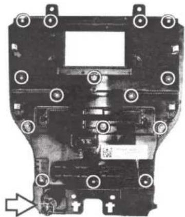
Remove fifteen screws and the 12v socket located behind the OEM climate control panel and retain for later install; then remove the PCB board back cover.
NOTE: The amount of screws may vary with each model. Retain the 12V socket from the OEM panel and place it on the aftermarket panel once removed from OEM panel.
natural_image
Close-up of a mechanical component with mounting holes and internal structure (no visible text or symbols)Step 9
Panel Preparation
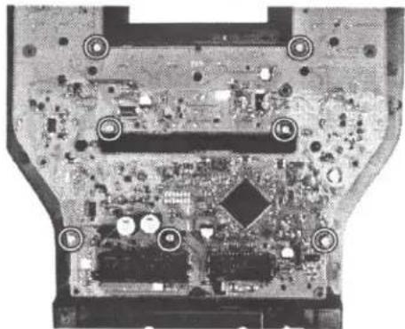
Remove the seven screws securing the PCB board to the panel; then remove from the panel.
NOTE: The amount of screws may vary with each models.
natural_image
Close-up of an electronic circuit board with visible components and mounting holes (no text or symbols)Step 10
Panel Preparation
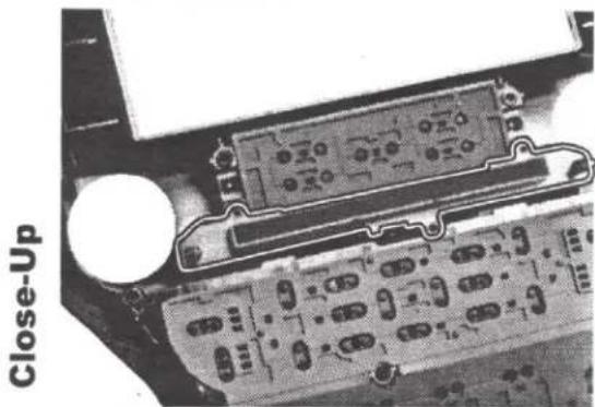
Lift and remove the plastic CD insert slot away from its location.
natural_image
Close-up of an electronic circuit board with labeled components and a circular component (no readable text or symbols)Step 11
Panel Preparation
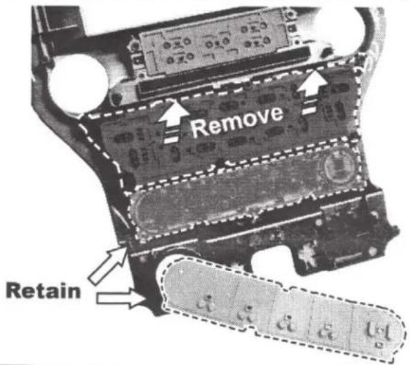
Lift and remove the drive train/ ignition controls and rubber pad from the OEM panel and retain for later install.
NOTE: Remove rubber and plastics blocking pieces needed in-order to remove the ignition controls (See image on the right).
INSTALLATION GUIDE
Panel Preparation
Step 12
Panel Preparation
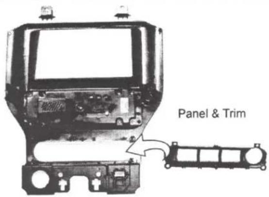
Place the drive train/ignition control trim into the (7773) face panel
Step 13
Panel Preparation
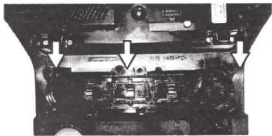
- Place the OEM drive train/ignition control buttons (retained in Step 11) into the trim from Step 12.
- Next Place the three provided PCB spacers Indicated by arrows on top of button controls.
natural_image
Close-up of an electronic component with visible circuitry and mounting holes (no text or symbols)Step 14
Panel Preparation
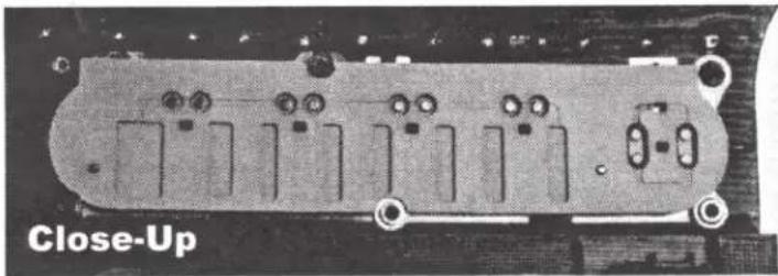
Place the rubber pad from the OEM drive-train controls onto the back of the buttons being cautious not to knock over the spacers placed on previous step.
natural_image
Close-up of an electronic component with multiple slots and mounting holes (no visible text or symbols)Step 15
Panel Preparation
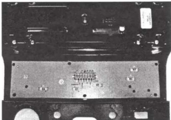
Carefully align the circuit board over the rubber pad, then continue to the next step.
natural_image
Close-up of a black electronic circuit board with visible traces and components (no readable text or symbols)Close-Up
INSTALLATION GUIDE
Panel Preparation
Step 16
Panel Preparation
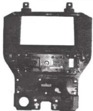
Place the back cover plate over the PCB and secure it using six screws retained in disassembly.
NOTE: Use the screws attained from the OEM PCB cover plate.
natural_image
Black-and-white photo of an electronic device casing with mounting brackets and internal components (no visible text or symbols)INSTALLATION GUIDE
Radio Installation
Step 17
Radio Installation
Single DIN ONLY:
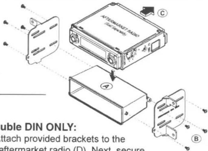
Attach brackets provided to the pocket (A), then secure the radio to the brackets (B). Lastly, secure radio assembly into dash cavity (C) and proceed to the next step.
Double DIN ONLY:
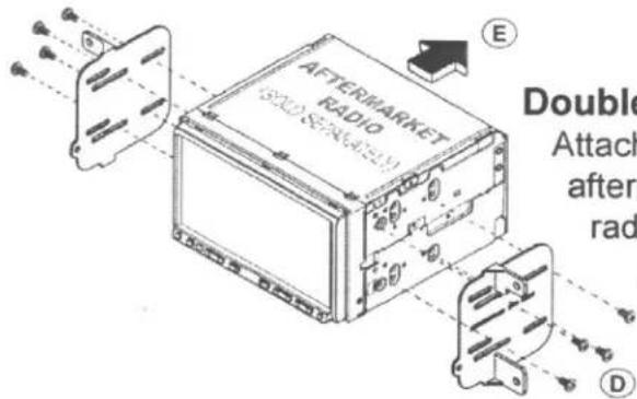
Attach provided brackets to the aftermarket radio (D). Next, secure radio assembly into the dash cavity (E) then proceed to the next step.
Step 18
Radio Installation
Connect and Reassemble everything in reverse order of the disassembly to complete the installation.
Note: 12v/cigarette plug are retained from OEM panel.
natural_image
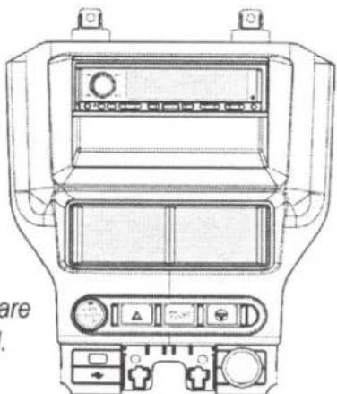
Top-down technical line drawing of a car air conditioning unit with control panel and buttons (no text or symbols)Single DIN Sample Illustration
natural_image
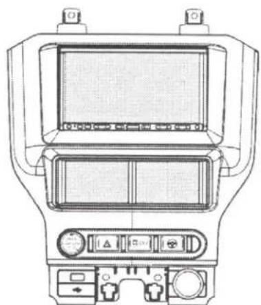
Top-down line drawing of a car dashboard with air condition meters and control panels (no text or symbols)Double DIN Sample Illustration
STEERING WHEEL WIRING CODES
Figure 1A
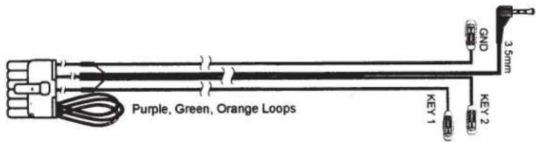
- Prepare SWC steering wheel connector harness by using the chart below
- Connect the harness to the interface module.
- For Alpine, Clarion, JVC, Panasonic and Sony car stereos, connect the 3.5mm male steering plug into the steering wheel input jack at the back of the stereo.
- For Kenwood and newer JVC stereos, connect the BROWN wire from the steering wheel harness to the "Remote in" wire at the back of the stereo.
| STEREO BRAND | CONFIGURATION | CONNECTION TO STEREO |
| ALIPNE | Cut Green Loop | 3.5mm |
| CLARION | Cut Violet Loop | 3.5mm |
| JVC | Cut Green & Violet Loop | 3.5mm or Brown (Key1) |
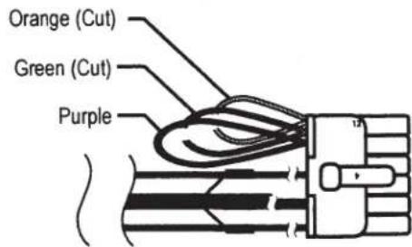
| KENWOOD | Cut Ornage & Green | Brown (Key 1) |
| PANASONIC | Cut Orange | Brown (Key 1) |
| PIONEER / SONY | Do Not Cut Loops | 3.5mm |
| OTHER BRANDS | Call Tech Support | Brown, Gray, Black |
NOTE: Do NOT remove, cut wires (See samples below).
Figure 1B Alpine Sample
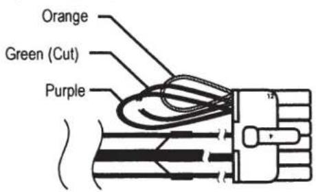
Figure 1C Kenwood Sample
STEERING WHEEL CONTROLS
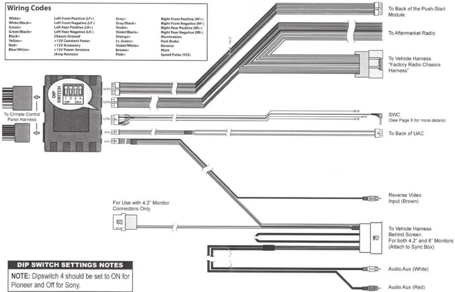
The Scosche ITCFD05B (2015-UP Ford Mustang) face panel comes with a steering wheel control harness that will retain the vehicles OEM steering wheel capabilities when equipped. Refer to the HVAC wiring
diagram for a connection guide. For further or more detailed understanding of the steering wheel controls, *please refer to your vehicles owner manual for button functionalities.
Steering Wheel Legend
- Track / Seek Down
- Volume Up
- Track / Seek Up
- Volume Down
- Voice Command (JVC/Alpine/Pioneer units with Voice Command Capabilities)
- Mute
- Phone Hang-UP (BT HU Only)
- Phone Pick-UP (BT HU Only)
*Refer to Vehicle Owner's Manual for buttons located on the left side of the steering wheel.
If you have any further questions, call our toll-free technical help line at:
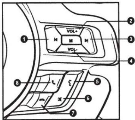
Steering Wheel Right Side Buttons Only
1-800-621-3695 x3
ITCFD05B WIRING DIAGRAM
Figure 2
CLIMATE CONVENIENCE CONTROL Left Screen
The Scosche Touch Screen Interface replaces the Factory climate, convenience and personalization controls built into the Factory Ford Radio/Dash panel. This solution provides improved ergonomics while adding touch screen capabilities unique to this system. Read the following sections to familiarize yourself with the operating controls and settings.
| 1. Press the Power Button (Fig.3, #1) to toggle the climate controls On or Off. | |
| 2. Press the Air Conditioning Button (Fig. 3, #2) to turn the Air Conditioning On or Off. A light will illuminate in the button indicating the on/off status of the A/C. | |
| 3. Press the recirculation button (Fig. 3, #3) to turn on air recirculation. A light will illuminate in the button indicating the on/off status of the Recirculate mode. Interior air will be re-circulated inside the vehicle. This mode helps to quickly cool the air inside the vehicle or prevent outside air and odors from entering. Operating recirculation mode [while the A/C is off] increases humidity and may cause the windows to fog. Recirculation is not available in the Defrost or Defog modes. | |
| MAX | 4.MAX A/Cbutton (Fig. 3, #4) on the color TFT touch screen to turn on Max A/C. Maximum cooling will occur with the temperature is adjusted to lowest cold setting and the Fan speed is set at maximum. MAX A/C is used to cool the car down as quickly as possible. Touch the Max A/C button again to return to the previous Fan speed and temp setting. |
| 5. To decrease fan speed, press the fan speed DOWN button (Fig. 3, #5). A graphic level indicator will move down on the color TFT screen indicating the current fan speed (Fig. 3, #7). | |
| 6. To increase fan speed, press the fan speed UP button (Fig. 3, #6). A graphic level indicator will move up on the color TFT screen indicating the current fan speed (Fig. 3, #7). There are a total of 7 fan speed increments from off to maximum. |
AIR FLOW / VENT CONTROL (Fig.3, #11)
Touch the vent control mode icons (Fig. 3, #11) on the color TFT touch screen to select vent mode.
Graphics are displayed according to the selected vent and airflow pattern.

Air is directed to the instrument panel vent outlets.

Air is directed to the instrument panel outlets and e floor ventoutlets.

Air is directed to the floor outlets

Air will be directed to the windshield and oor and/or side vent outlets.

Air will be directed to the front and rear windows only.
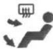
Air will be directed to the instrument panel vents and rear window


Indication light will illuminate on right screen (See Page 11).

Indication light will illuminate on right screen (See Page 11).
CLIMATE & CONVENIENCE CONTROLS (Left Screen Cont'd)
TEMPERATURE CONTROL (Page 10 Fig. 3, #8-10)
Use the UP and DOWN arrows (Page 10 Fig. 3, #8 & #10) on the color TFT touch screen to adjust vehicle air temperature. Touch the Red
CLIMATE & CONVENIENCE CONTROLS (Right Screen)
- Driver Heated Seat
- Passenger Heated Seat
- Rear Derost
- Front Defrost
- Outside Temp. Reading
- Time Display
- Scosche Logo
- Menu
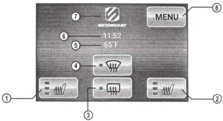
 | DRIVER HEATED SEATS1. Touch the driver's seat heater button (Fig. 4, #1) on the color TFT touch screen to turn on the driver's seat heater. The engine must be running to use heated seats. A Button graphic will show the level of heat selected (low, medium, or high). Press the button repeatedly to cycle through the temperature settings or to turn the heated seat OFF. |
 | PASSENGER HEATED SEATS2. Touch the passenger's seat heater button (Fig. 4, #2) on the color TFT touch screen to turn on the Passenger's seat heater. The engine must be running to use heated seats. A button graphic will show the level of heat selected (low, medium, or high). Press the button repeatedly to cycle through the temperature settings or to turn the heated seat OFF. |
 | 3. Press the Rear window derost button (Fig. 4, #3) to turn the rear window defogger on or off. A light will illuminate in the button indicating the on/off status of the Defrost mode. Rear defogger will also be turned off by turning the ignition to the OFF position. |
 | 4. Press the Front Defrost (Fig. 4, #4) to turn Defrost On or Off. This configuration helps clear front windshield of fog or moisture. Air will be directed to the windshield. A light will illuminate in the button indicating the on/off status of the Defrost mode. NOTE: For best results clear the windows of snow or ice before defrost settings. DO NOT OPERATE VEHICLE UNTIL WINDOWS ARE CLEAR! |
 | 5. Convenient reading of outside temperature. Enter menu settings to configure Celsius or Fahrenheit. |
T  e e | 6. Digitally displays time, enter Menu settings to configure time formate (12HR/24HR). Tap the displayed time on the screen to enable date window displaying for 3sec. |
 | 7. Tap Scosche 4x and hold to enable installer menu. Installer menu can be found under vehicle settings. Please refer to chart Installer Menu Chart on page 13. |
| MENU | 8. MENU allows the user to configure Vehicle Settings (Installer Menu) / ITC Settings / Language settings. Within menu settings the user can also refer to module version for technical reference. Please refer to Charts on page 13 & 14 for further details. |
MENU NAVIGATION
MENU Press the MENU button (Page 11 Fig.4, #8) to access Configuration Menu Vehicle/Interface/Language/Version Settings
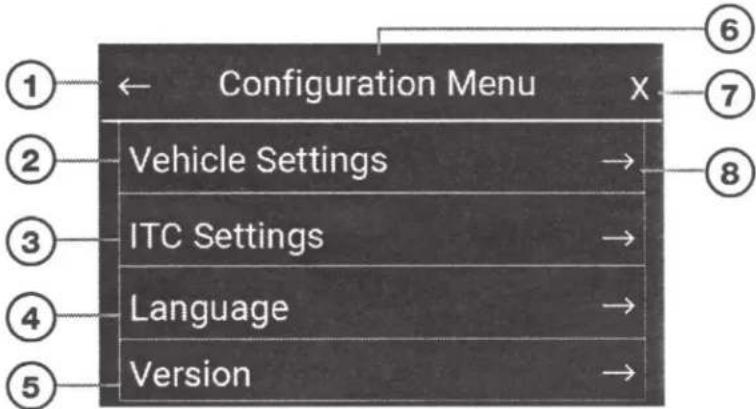
The following figures (5-7) are sample menu screen displays to help you navigate and understand the menu user interface of the module. Use the ←(Return arrow) to go back to the previous menu. Press the X to close the menu window and return to the TFT color touch screen home screen. For further setting options refer to the Vehicle Settings Chart on Page 13, Installer Menu Chart on page 13, ITC Settings Chart on page 14 & Language Software Setting Chart on page 14.
Figure 5
Navigation of Menu Settings
- Return to Previous menu
- Enter Vehicle Settings menu
- Enter ITC Settings menu
- Enter Language selection menu
- Enter module Version menu
- Menu title header
- Close menu settings
- Arrow indicates more sub- menus for selected setting
flowchart
graph TD
    A["Configuration Menu"] --> B["Vehicle Settings"]
    A --> C["ITC Settings"]
    A --> D["Language"]
    A --> E["Version"]
    style A fill:#000,stroke:#fff,color:#fff
    note1["①"] --> A
    note2["②"] --> A
    note3["③"] --> A
    note4["④"] --> A
    note5["⑤"] --> A
    note6["⑥"] --> A
    note7["⑦"] --> A
    note8["⑧"] --> A
Figure 6
Sub-menu Settings Settings
- Return to Previous menu
- Sub-menu configuration options
- Sub-menu title header display
- Close menu
- Scrollbar [Scroll Up/Down for more options (Only when displayed)]
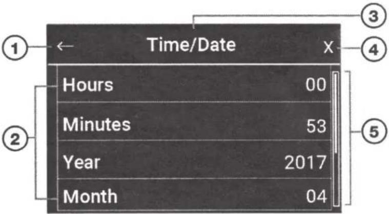
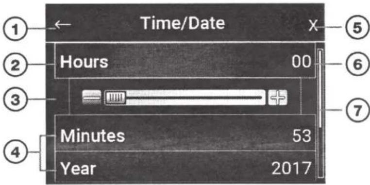
Figure 7
Configure Settings for Options
- Return to previous menu
- Setting highlighted when selected.
- Setting Scrollbar (Use to customize setting)
- Options not selected (Press to select)
- Close menu
- Set setting (Use slider to customize setting)
- Scrollbar (when available)
VEHICLE CONFIGURATION SETTINGS CHART
Use the charts on this page (13) and the charts on page 14 to navigate through the different settings the "Menu" touch screen display has to offer. Also use the chart to see the different configuration settings offered with the kit.
| FEATURE NAME | Option 1 | Option 2 | Option 3 | Option 4 | Option 5 | Option 6 | Option 7 |
| Time/Date | Hours | Minutes | Year | Month | Day | Set Time Format | Set Date Format |
| 00-23 | 00-59 | 2000-2099 | 1-12 | 1-31 | DD.MM.YYYY MM.DD.YYYY YYYY.MM.DD | 12HR 24HR | |
| Note: Adjust desired setting using the slide bar's - and the + on the touch screen | |||||||
| Distance Units | KM | Miles | |||||
| Temp. Units | °C | °F | |||||
Accessing Installer Menu:
To access the installer menu repeatedly tap the Scosche logo on the FTF home touch screen until pop-up notification "Installer Menu Enabled" is displayed on right home screen
Select Menu then under the Configuration Menu enter Vehicle Settings.
Once in Vehicle Settings, installer menu will be located underneath Temperature Units setting. Press and select the option, Installer Menu to enter settings.
VEHICLE SETTINGS (Installer Menu)
| FEATURE NAME | Option 1 | Option 2 | Option 3 | Option 4 | Option 5 | Option 6 | Option 7 |
| Select Vehicle | F150 | Mustang | |||||
| Heated Seats | Fitted | Not Fitted | |||||
| Heated Rear Screen | Fitted | Not Fitted | |||||
| Camera Type | None | Type 1 | Type 2 | ||||
ITC SETTINGS CHART
| FEATURE NAME | Option 1 | Option2 | Option 3 |
| Brightness (Day) | 0% to Auto (100%) | ||
| Note: Use the Negative - and Positive touch screen buttons to scroll and set desired percentage setting | |||
| Brightness (Night) | 0% to Auto (100%) | ||
| Note: Use the Negative - and Positive touch screen buttons to scroll and set desired percentage setting | |||
| Day Night Automatic | Day | Night | Automatic |
| Touch Volume | 0% to 100% | ||
| Note: Use the Negative - and Positive touch screen buttons to scroll and set desired percentage setting | |||
| Display External Temp. | Yes | No | |
| Park Brake Source | Brake | Speed | |
| Enhanced Park Pilot | Off | On | |
| Camera Delay | Off | On | |
LANGUAGE & SOFTWARE SETTINGS CHART
| FEATURE NAME | Option 1 | Option2 | Option 3 |
| Language | English | Français | Español |
| Version | MCU: HVAC for Ford v1.05Resource: Ford Resource v1.06ACU: Ford HVAC Controller v1.10Roboto: Font data copyright Google 2014 | ||
NOTES
NOTES

SCOSCHE
ITCFD05B
FORD MUSTANG, 2015-UP
Single-Zone Climate Control Models
Integrated Touchscreen II (ITC 2.0) Control Solution
Dash Kit - Double DIN / Single DIN with pocket
ITCFD05B
FORD MUSTANG, 2015-UP
Single-Zone Climate Control Models
Integrated Touchscreen II (ITC 2.0) Control Solution Dash Kit - Double DIN / Single DIN with pocket
FEATURES
• Built-in Advance Color Touch-screen Control System Retains:
• Climate Controls
• Steering Wheel Controls
- Heated Seats (If Equipped)
• Vehicle OE Personalization Menus & Setting
• Accommodates OEM Toggle or OEM Push Button Switches
- Integrated Stereo Replacement Interface
• Accommodates ISO Double DIN & Single DIN ◆ Pocket Installations
• Reinforced Panel Structural Design w/ Automotive-Grade ABS+PC Material
• Factory-matched Contours and Gun Metal Color
• ISO Side Mounting Brackets Included
• Wiring Harness & Antenna Adapter Included
• Retains Reverse Backup Camera


SCOSCHE

SCOSCHE.com
ITCFD05B
AVAILABLE COLORS: GUN METAL
ITCFD05B
2015-UP Ford Mustang
Integrated Touchscreen Control Solutions
Join by Designed and Engineered in the
U.K and U.S.A. Custom Manufactured in China.
©2017 SCOSCHE INDUSTRIES, INC.
1550 Pacific Ave., Oxnard, CA 93033

Designed & engineered in
California, USA by Scosche
Custom Manufactured in China.
001CFDOSB 05/17

Tech Support/Secours
805-486-4450X3
California Proposition 65 WARNING: This product contributes chemical(s) known to the State of California to capex, optical and birth defects and other reproductive home
- IN-DASH INSTALLATION KIT FOR
- 2015-UP FORD MUSTANG
- SINGLE ZONE MANUAL CLIMATE CONTROLS
- Kit Content
- Instruction Index PG
- Tools Required
- NOTICE:
- INTRODUCTION / PRELIMINARY
- NOTES
- STOP
- IMPORTANT!
- LIABILITY DISCLAIMER
- INSTALLATION GUIDE
- Step 1
- Image A:
- Image B:
- Step 2
- Step 3
- Step 4
- Step 5
- Step 6
- CAUTION
- Step 7
- Step 8
- Step 9
- Step 10
- Step 11
- Step 12
- Step 13
- Step 14
- Step 15
- Step 16
- Step 17
- Single DIN ONLY:
- Double DIN ONLY:
- Step 18
- STEERING WHEEL WIRING CODES
- STEERING WHEEL CONTROLS
- Steering Wheel Legend
- CLIMATE CONVENIENCE CONTROL Left Screen
- AIR FLOW / VENT CONTROL (Fig.3, #11)
- CLIMATE & CONVENIENCE CONTROLS (Left Screen Cont'd)
- TEMPERATURE CONTROL (Page 10 Fig. 3, #8-10)
- CLIMATE & CONVENIENCE CONTROLS (Right Screen)
- MENU NAVIGATION
- MENU Press the MENU button (Page 11 Fig.4, #8) to access Configuration Menu Vehicle/Interface/Language/Version Settings
- VEHICLE CONFIGURATION SETTINGS CHART
- Accessing Installer Menu:
- SCOSCHE
- ITCFD05B
- FORD MUSTANG, 2015-UP
- FEATURES
Brand : Scosche
Model : ITCFD05B
Category : Uncategorized