
Ultima Pre 3 - Receiver Chord - Free user manual and instructions
Find the device manual for free Ultima Pre 3 Chord in PDF.


| Product Type | Preamplifier/Receiver |
| Brand | Chord |
| Model | Ultima Pre 3 |
| Dimensions (W x H x D) | 430 mm x 80 mm x 320 mm |
| Weight | 8 kg |
| Power Supply | 100-240 V AC, 50/60 Hz |
| Power Consumption | 40 W (standby < 0.5 W) |
| Inputs | 4x RCA, 2x XLR, 1x USB |
| Outputs | 2x RCA, 2x XLR, 1x headphone 6.3mm |
| Frequency Response | 5 Hz - 100 kHz (±0.5 dB) |
| Total Harmonic Distortion | < 0.001% |
| Signal-to-Noise Ratio | > 120 dB |
| Gain | 12 dB (RCA), 18 dB (XLR) |
| Input Impedance | 47 kΩ (RCA), 10 kΩ (XLR) |
| Output Impedance | 100 Ω (RCA), 50 Ω (XLR) |
| Main Functions | Input selection, volume control, mute, balance, tone control (bypassable) |
| Remote Control | Infrared remote included |
| Display | OLED screen with input and volume indication |
| Materials | Aluminum chassis, brushed finish |
| Maintenance | Wipe with dry cloth; avoid solvents. Keep vents clear. |
| Safety | Class II, double insulated. Do not expose to moisture. |
| Spare Parts / Repairability | Contact Chord support or authorized service centers. Typical spare parts: volume knob, remote, power supply module. |
| General Information | Designed for audiophile systems. Compatible with Chord amplifiers. Firmware update via USB. |
Frequently Asked Questions - Ultima Pre 3 Chord
User questions about Ultima Pre 3 Chord
0 question about this device. Answer the ones you know or ask your own.
Ask a new question about this device
Download the instructions for your Receiver in PDF format for free! Find your manual Ultima Pre 3 - Chord and take your electronic device back in hand. On this page are published all the documents necessary for the use of your device. Ultima Pre 3 by Chord.
USER MANUAL Ultima Pre 3 Chord
Chord Electronics Ltd.

natural_image
Technical line drawing of a heat exchanger or cooling unit with multiple fans and cooling fins (no text or symbols)Contents 0.0
1.0 Safety 03
1.1 Introduction 04
1.2 Protection against liquids and heat 05
1.3 Dismantling and radio 06 frequency interference
1.4 Connecting other equipment 07
2.0 Warranty 08
2.1 Warranty and registering 09
2.2 Claims and exclusions 10
3.0 Panels and remote control 11
3.1 Familiarisation 12
3.2 The front panel 13
3.3 The rear panel 14
3.4 The remote control 15
4.0 Set up and installation 16
4.1 Placement 17
4.2 Connecting inputs 18
4.3 Connecting to a power amplifier 19
4.4 AV bypass 20
4.5 Other rear panel connections 21
5.0 Operation 22
5.1 Basic operation 23
5.2 Volume and input select 24
5.3 Balance and AV bypass 25
5.4 Dimmable lighting 26
6.0 Technical specifications 27
6.1 Technical specifications 28
0.0
Contents
Safety 1.0
1.1 Introduction
1.2 Protection against liquids and heat
1.3 Dismantling and radio frequency interference
1.4 Connecting other equipment
1.0
Safety
Introduction 1.1

The ULTIMA PRE 3 is an advanced, ground-up design preamplifier built to complement ULTIMA amplification.
It benefits from five inputs: two stereo pairs of XLRs for balanced connections, plus three RCA pairs for unbalanced connections. An XLR AV bypass is also included for use with compatible AV processors and receivers. Outputs include XLR and RCA connections, a 5 V/3 A USB power output (for Qutest and Hugo 2 DACs, plus general USB charging), and a 12 V trigger for powering other compatible devices.

natural_image
Exterior view of a silver industrial fan or compressor unit with control knobs and a blue vent (no visible text or symbols)
Made in BRITAIN
Protection against
liquids and heat
1.2

The ULTIMA PRE 3 is not protected against liquids of any kind. Never place containers of liquid on the unit, or allow it to come into contact with moisture or liquids, doing so could result in electrocution or damage.
Be aware that liquids, including water which has dried, can leave minerals that can affect the PCB and other components, which could eventually lead to oxidisation and short-circuiting.
If the ULTIMA PRE 3 comes into contact with moisture or liquids, immediately disconnect it from the power supply and connected equipment, and contact Chord Electronics for further advice.

The device has internal thermal protection which will shut the unit down in the event of excessive temperatures being reached. Never operate the device near sources of heat or naked flames, as this will decrease the lifespan of the internal components. Avoid operating the device in an area of direct sunlight, or on top of significant heat-producing devices.
Note: it is entirely normal for the device to become warm during use, particularly if stacked. If necessary, switch the unit off or consider different placement.
Dismantling and radio frequency interference
1.3

There are no user-serviceable components within the ULTIMA PRE
3 or its power supply. Dangerous voltages/currents exist within the ULTIMA PRE 3 and its power supply, potentially posing a severe risk of electrocution and/or fire.

Never attempt to open, dismantle or apply
internal third-party devices to it, or insert anything other than appropriate interconnects or power cables suggested within this user manual.
If the device develops a fault, or the casework becomes damaged, immediately disconnect from the power supply and connected equipment, and contact Chord Electronics or the supplying dealer for further advice.
With a thick, solid aluminium chassis, the ULTIMA PRE 3's casework protects the sensitive internal circuitry from radio frequency interference. However, for optimal performance, it is recommended that the following points are observed:

- Consider placing the ULTIMA PRE 3 away from wireless routers.

- Operate mobile phones at a distance to avoid interference.
Connecting other equipment 1.4
Before connecting the device to other equipment, consult the respective manufacturer's user guide to confirm compatibility.
When connecting the ULTIMA PRE 3 to other equipment, make sure that all devices are switched off. A 10-amp IEC mains lead is supplied.
Once fully connected, switch all equipment on, starting with the source and ending with the amplification.
Initially, operate any connected equipment at the lowest volume, gently increasing to a comfortable level.
Never operate the device or connected equipment at excessive sound levels: permanent hearing damage and loss could occur.
If the power supply is prematurely disconnected, the device may still remain active for up to 15 seconds.

Never disconnect the power cable during operation.
Only disconnect when the ULTIMA PRE 3 is off. If the power cable is disconnected during operation, there is a risk of damage to connected equipment.

natural_image
Exterior view of a silver industrial device with dual control knobs and a green vent (no visible text or symbols)Warranty 2.0
2.1 Warranty and registering
2.2 Claims and exclusions
2.0
Warranty
Warranty and registering 2.1
At the point of sale, Chord Electronics Ltd. provides the ULTIMA PRE 3 with a comprehensive five-year warranty* that covers defects in materials and workmanship through fair wear and tear. Note: the warranty will be void if a power supply other than that supplied is used.
*The warranty is transferable with proof of purchase, however, the warranty on ex-demonstration units begins from the retailer's date of purchase.


Use the form below to record details. Purchases should be
registered at:
chordelectronics.co.uk/register-product/
| RETAILER: | |
| PURCHASE PRICE: | |
| UNIT COLOUR: | |
| DATE OF PURCHASE: | |
| TRANSACTION ID: |
Claims and exclusions 2.2
In the unlikely event of a claim, purchase details and the serial number will be needed in order to validate the warranty status and any possible repair/s.
Upon receipt of the device, Chord Electronics will make an assessment within 30 days and provide resolution options.
All warranty repairs must be carried out by Chord Electronics, or an approved service centre to guarantee the quality and safety of the repair.
WARRANTY EXCLUSIONS: The warranty does not cover connected equipment, personal injury or the development of a natural patina of the metalwork and will be null and void if the following is applied: wilful neglect; modification or tampering; improper use of the product; acts of God; damage caused by a connected device; mechanical shock; fire or application of excessive heat or repair/modification by a non-authorised third-party vendor.
Panels and remote control 3.0
3.1 Familiarisation
3.2 The front panel
3.3 The back panel
3.4 The remote control
3.0
Panels and remote control
Familiarisation 3.1
The ULTIMA PRE 3 is a five-input preamp with both balanced and unbalanced inputs and outputs. Its contemporary design makes it the ideal 'hub' for a Chord Electronics audio system.

natural_image
Exterior view of a modern stainless steel electronic device with dual switches and a central fan (no visible text or symbols)3.1 Familiarisation
3.2 The front panel
3.3 The back panel
3.4 The remote control
The front panel 3.2
The front panel features the volume/input-selector control, power button and balance/AV bypass control.

3.1 Familiarisation
3.2 The front panel
3.3 The back panel
3.4 The remote control
The back panel 3.3
The rear panel houses the device's wide-ranging connectivity.


WARNING: Do not use any other power supplies other than
that supplied. Doing so will invalidate the warranty.
The remote control 3.4
The remote control offers control over the ULTIMA PRE 3, plus selected Chord Electronics devices. The top section is reserved for the BLU MKII CD digital transport, while the bottom section is used for the ULTIMA PRE 3.
As the infra-red remote control requires a direct line of sight to the preamp's power button, avoid placing objects in front of either device.
NOTE: The remote will need to be in hi-fi mode to work with the Pre 3. Press the hi-fi button to enter this mode. The annotated image (right) provides a key to button operation.
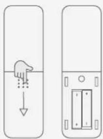

NOTE: Only insert AAA batteries into the remote control and observe the correct orientation as indicated.
Set up and installation 4.0
4.1 Placement
4.2 Connecting inputs
4.3 Connecting to a power amplifier
4.4 AV bypass
4.5 Other rear panel connections
4.0
Set up and installation
4.1 Placement
4.2 Connecting inputs
4.3 Connecting to a power amplifier
4.4 AV bypass
4.5 Other rear panel connections
Placement 4.1
When positioning the device, allow a minimum of 15 cm all round for convection-cooling. Avoid placement inside cabinets etc.

natural_image
Exterior view of a modern audio amplifier device with visible buttons and ventilation grilles (no text or symbols)Connecting to power and inputs
4.2
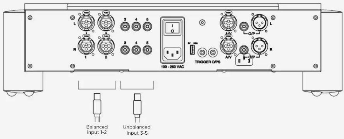
Up to five source components can be connected using balanced (XLR) and unbalanced (RCA) interconnects. Ensure that all units are switched off before connections are made and that all are securely attached.
The AV bypass XLR input is located to the right of the 12 V trigger outputs.
Each input is arranged as a stereo pair, L (left top), R (right bottom).
The outputs (XLR and RCA) for connection to power amps and active speakers etc. can be found on the right of the unit.
Connect the supplied 10 A power cable to the IEC inlet socket and then to a power supply at the wall. Note: only when all connections are made and the volume set to minimum, should the preamp be switched on.
4.1 Placement
4.2 Connecting inputs
4.3 Connecting to a power amplifier
4.4 AV bypass
4.5 Other rear panel connections
Connecting
4.3
to a power amplifier
Using the XLR or RCA outputs shown in the illustration, connect the ULTIMA PRE 3 to the power amplifier's corresponding inputs.

AV bypass 4.4
The AV bypass feature allows the output of an AV processor or receiver to directly connect to the preamp's output. The preamp's volume control and signal processing are then bypassed, so that the signal from the AV device reaches connected power amplifiers as if it were connected directly.
This can be useful for watching video with high-quality two-channel audio.
To connect the preamp to an AV device using AV bypass:
1) Locate the XLR AV bypass input shown below and connect to the corresponding output on the partnering AV device, checking the device's manual if required.
2) Select the appropriate output on the connected AV device and ensure the AV bypass mode has been selected on the preamp (see page 24).
WARNING: The volume control on the preamp will be bypassed, so check the connected AV device's volume has been turned down before increasing volume.

Other rear panel connections 4.5
The ULTIMA PRE 3 features three additional connections: a 5 V/3 A USB power output, 12 V trigger output and a grounding post.
5 V/ 3 A USB power output:
The 5 V/3 A USB power output is a convenience feature allowing a range of compatible devices, including the Chord Electronics Mojo and Mojo 2, Qutest and Hugo 2 DACs etc., to be powered directly via a USB-A to Micro-USB cable from the ULTIMA PRE 3, negating the need for individual power supplies.
The USB power output can also be used to power/charge other compatible USB devices, such as smartphones and tablets.
12 V trigger output:
The ULTIMA Pre 3 can be used to 'wake' other units from (and return them to) standby, when connected via a 12 V trigger. Connect the ULTIMA PRE 3's 12 V trigger output to other 12 V-trigger-compatible devices with an appropriate 3.5mm mini-jack cable, in order to use the feature.
Grounding post (device earthing):
In some European countries, hum or buzz may occur if the amplifier is connected to power sockets that do not have an earth or adequate earth. The ULTIMA PRE 3 has a grounding post, situated above the 12 V trigger input/output.
To ground the device, unscrew the locking earth-pin (we recommend three turns) and attach a suitable earthing wire before screwing back the locking earth-pin thumb-tight.
Operation 5.0
5.1 Basic operation
5.2 Volume and input select
5.3 Balance and AV bypass
5.4 Dimmable lighting
5.0
Operation
Basic operation 5.1
The preamp has an on/off rear-mounted rocker switch. When switched on, the unit enters standby mode, indicated by a red colour from the fascia power button. Pressing the power button on the fascia or remote control 'wakes' the preamp from standby into operation mode. The two-second boot-up sequence turns the power button from red to green. Once ready for playback, the power button will click and display teal.
The ULTIMA PRE 3 can be used with the remote control or front panel.
Volume and input select 5.2
The volume/IP control knob can be used to adjust the volume and select between the preamp's five inputs.
The volume is conventionally increased/decreased by turning the volume/IP knob clockwise/anticlockwise, respectively.
Note: The output can be muted/unmuted using the remote control only, the power button will change to green accordingly. This can only be un-muted using the remote control. When unmuted the power button will return to teal.
Note: Ensure the volume is set to the minimum level (fully anticlockwise) before slowlyincreasing to a comfortable level. Inputs can be selected by pushing the volume knob inwards repeatedly to sequentially select between inputs 1-5. Each input is indicated by a click and a coloured light around the volume control as follows:
Input Button colour
| Input 1: Balanced XLR | |
| Input 2: Balanced XLR | |
| Input 3: Unbalanced RCA | |
| Input 4: Unbalanced RCA | |
| Input 5: Unbalanced RCA |
Balance and AV bypass 5.3
Balance and AV bypass adjustments are combined on one control knob. The balance control enables fine adjustments between left and right channels and is factory-set to neutral/equal when the Balance/AV control is set to the 12 o'clock position. Rotating the knob clockwise or anticlockwise will adjust the bias to the right or left channels, respectively.
To active the AV bypass mode, ensure that all relevant connections have been made (see page 20) and press the Balance/AV control knob inwards to click (the light around the control knob will change from white to purple and the volume control knob lights will extinguish). Pressing Balance/AV a second time will deactivate AV bypass mode and the light around the control will return to white.
Note: When selecting AV bypass mode, the ULTIMA PRE 3 volume control is bypassed. Therefore, check that the volume of the connected AV device is either at the minimum or at a low level before increasing to a comfortable level. When deselecting AV bypass mode, also ensure the ULTIMA PRE 3's volume control is either at the minimum or at a low level before increasing to a comfortable level.

Dimmable lighting 5.4
The lighting level of the front panel and top panel LED ring can be dimmed using the remote control. Press 'DIM' to reduce the brightness, pressing again to restore.
Technical specifications 6.0
6.1 Technical specifications
6.0
Technical specifications
Technical specifications 6.1
| Frequency response 10 Hz-200 kHz +/- 3 dB | |
| THD 0.002 % 20 Hz-20 kHz | |
| Signal to noise ratio -105 dB on all inputs | |
| Input impedance 100 kΩ | |
| Output impedance 560 Ω | |
| Input maximum voltage 10 V RMS | |
| Output maximum voltage 17 V RMS | |
| Gain x1 | |
| Channel separation 100 dB | |
| Operation voltage 80-250 V AC auto-switching | |
| Power consumption 40 W | |
| Dimensions | 355 mm (L) x 485 mm (W) x 130 mm (H) |
| Net Weight | 12.7 kg |

Chord Electronics Ltd.

- Contents 0.0
- Safety 03
- Warranty 08
- Panels and remote control 11
- Set up and installation 16
- Operation 22
- Technical specifications 27
- Safety 1.0
- 1.0
- Safety
- Introduction 1.1
- Protection against
- liquids and heat
- 1.2
- Dismantling and radio frequency interference
- Connecting other equipment 1.4
- 2.0
- Warranty
- Warranty and registering 2.1
- Claims and exclusions 2.2
- 3.0
- Panels and remote control
- Familiarisation 3.1
- The front panel 3.2
- The back panel 3.3
- The remote control 3.4
- 4.0
- Set up and installation
- Placement 4.1
- Connecting to power and inputs
- Connecting
- to a power amplifier
- AV bypass 4.4
- Other rear panel connections 4.5
- V/ 3 A USB power output:
- V trigger output:
- Grounding post (device earthing):
- Operation 5.0
- 5.0
- Operation
- Basic operation 5.1
- Volume and input select 5.2
- Balance and AV bypass 5.3
- Dimmable lighting 5.4
- 6.0
- Technical specifications
- Technical specifications 6.1
Brand : Chord
Model : Ultima Pre 3
Category : Receiver