
HMD-VS1W - Headphones JVC - Free user manual and instructions
Find the device manual for free HMD-VS1W JVC in PDF.


| Product type | Wired audio headset |
| Brand | JVC |
| Model | HMD-VS1W |
| Dimensions (approx.) | 200 x 150 x 50 mm (folded) |
| Weight (approx.) | 200 g |
| Power supply | Via audio cable with 3.5 mm jack connector |
| Main functions | Stereo audio playback, volume adjustment (on cable) |
| Maintenance and cleaning | Clean with a dry cloth, do not use liquids |
| Safety instructions | Do not use near water, do not open, unplug during storms |
| Spare parts and repairability | Repair by qualified personnel only, no spare parts provided |
| General information | Compliant with FCC Part 15 (Class A), European electromagnetic compatibility standards |
Frequently Asked Questions - HMD-VS1W JVC
User questions about HMD-VS1W JVC
0 question about this device. Answer the ones you know or ask your own.
Ask a new question about this device
Download the instructions for your Headphones in PDF format for free! Find your manual HMD-VS1W - JVC and take your electronic device back in hand. On this page are published all the documents necessary for the use of your device. HMD-VS1W by JVC.
USER MANUAL HMD-VS1W JVC
natural_image
Technical line drawing of a mechanical device with hoses and components (no text or symbols)Thank you for purchasing this JVC product.
Please read this "INSTRUCTIONS" prior to use to ensure proper use of this unit.
Be sure to read the (pages P. 4 to P. 8) especially for safe use of this unit.
For Customer use :
Enter below the serial No. which is located on the body.
Retain this information for future reference.
Model No. HMD-VS1W, HMD-VS1DW
Serial No.
Contents
Getting Started
Accessories 3
Check the Accessories 3
Safety Precautions 4
Warning 8
Precautions 8
Name of Parts 12
Front 12
Rear 13
Set up
Putting on 14
Precautions during Use 14
Putting on the Head-mounted Display 14
Connection 17
Connecting with a PC 17
Connecting the Power Cord 17
Initial Configuration 18
Operate
Viewing Videos 20
Adjust/Set
About the Software 22
IPD Adjustment Software 22
HMD Configuration Software 23
Maintenance
Servicing of the HMD Unit 27
Replacement of Consumable Parts 28
Forehead and Face Pads 28
Rear Pad 28
Nose Pad 29
Adjustment Band 29
Protect Filter (HMD-VS1DW) 30
Disinfection of Product 32
Long-term Storage 33
Troubleshooting
Troubleshooting 34
Others
Use of Commands 36
List of Commands 37
Specifications 38
About Trademarks and Copyrights 39
Index 40
* The illustrations of the HMD unit used in this manual are those of HMD-VS1W. The appearance of other models may differ slightly.
Accessories
Check the Accessories
AC adapter 1 piece
Power cord (for use in the U.S.) 1 piece
Power cord (for use in Europe) 1 piece
- This product also comes with a safety precautions guide.
- Be sure to read the "Safety Precautions" before using this equipment.
Safety Precautions
These are general Important Safety Instructions and certain items may not apply to all appliances.
Important Safety Instructions
- Read these instructions.
- Keep these instructions.
- Heed all warnings.
- Follow all instructions.
- Do not use this apparatus near water.
-
Clean only with dry cloth.
-
Do not block any ventilation openings. Install in accordance with the manufacturer's instructions.
-
Do not install near any heat sources such as radiators, heat registers, stoves, or other apparatus (including amplifiers) that produce heat.
-
Protect the power cord from being walked on or pinched particularly at plugs, convenience receptacles, and the point where they exit from the apparatus.
-
Only use attachments/accessories specified by the manufacturer.
-
Use only with the cart, stand, tripod, bracket, or table specified by the manufacturer, or sold with the apparatus. When a cart is used, use caution when moving the cart/apparatus combination to avoid injury from tip-over.
-
Unplug this apparatus during lightning storms or when unused for long periods of time.
-
Refer all servicing to qualified service personnel. Servicing is required when the apparatus has been damaged in any way, such as power-supply cord or plug is damaged, liquid has been spilled or objects have fallen into the apparatus, the apparatus has been exposed to rain or moisture, does not operate normally, or has been dropped.
-
Never push objects of any kind into this product through openings as they may touch dangerous voltage points or short out parts that could result in a fire or electric shock. Never spill liquid of any kind on the product.
-
Do not overload wall outlets, extension cords, or convenience receptacles on other equipment as this can result in a risk of fire or electric shock.

The lightning flash with arrowhead symbol, within an equilateral triangle is intended to alert the user to the presence of uninsulated "dangerous voltage" within the product's enclosure that may be of sufficient magnitude to constitute a risk of electric shock to persons.

The exclamation point within an equilateral triangle is intended to alert the user to the presence of important operating and maintenance (servicing) instructions in the literature accompanying the appliance.
ATTENTION
RISQUE D'ELECTROCUTION NE PAS OUVRIR


ATTENTION:
POUR EVITER TOUT RISQUE D'ELECTROCUTION NE PAS OUVRIR LE BOITER. AUCUNE PIECE INTERIEURE N'EST A REGLER PAR L'UTILISATEUR. SE REFERER A UN AGENT QUALIFIE EN CAS DE PROBLEME.
The mains plug shall remain readily operable.
- Remove the mains plug immediately if the product functions abnormally.
WARNING: TO PREVENT FIRE OR SHOCK HAZARD, DO NOT EXPOSE THIS UNIT TO RAIN OR MOISTURE.
The apparatus shall not be exposed to dripping or splashing and that no objects filled with liquids, such as vases, shall be placed on the apparatus.
NOTES:
- The rating plate and safety caution are inside and/or the back of the main unit.
- The rating information and safety caution of the AC adapter are on its upper side.
Attention:
- As the power plug (main plug) is used to disconnect the unit from the wall outlet (mains), connect the unit to an easily accessible AC outlet.
- Should you notice an abnormality in the unit, disconnect the power plug (main plug) from the AC outlet (mains) immediately.
- The set is not disconnected from the AC power source (mains) as long as it is connected to the wall outlet (mains), even if the set itself has been turned off.
Precautions
Power Supply
Position the AC adapter near the wall outlet (mains) used. In case of strange noises, fumes, or smoke from the system, immediately unplug the AC power cord (mains lead) to turn all power off. Only turning the power switch of the head mounted display off will not turn the system off completely.
AC Adapter
- Use the attached AC Adapter and power cable.
- Do not use any unspecified adapter. It may cause failure of the product.
- Performance and safety are not guaranteed if any other AC power cord (mains lead) than those exclusive to this system is used.
- Do not disassemble or modify the AC adapter.
- Do not touch metal parts of the AC adapter. Especially keep in mind that touching it with a metal tool may cause a short-circuit, damaging the AC adapter.
Installation Environment
Avoid installation in the following environments.
- This device is not suitable for use in places where children are
• In direct sunlight, or where it is very hot or humid - Places that are extremely cold
Operation Environment
Use this product in a safe place.
- Use this product by paying close attention to people and obstacles around you.
- Do not use this product in a place where your body is unstable. Doing so may cause the user to fall or result in injury.
- Do not walk while wearing this product.
- Use this product by wearing it appropriately. For details on how to wear this product, refer to "Wearing This Product".
- Before using this product, adjust the distance between the pupils of your eyes. Failure to do so may cause fatigue or discomfort to your eyes.
Health Concerns
- Please refrain from using the devices when you feel tired, unwell or if you feel any other discomfort.
- Persons with photosensitivity, any kind of heart disease, or weak health should not use the equipment.
Supplier's Declaration of Conformity
Model Number: HMD-VS1W, HMD-VS1DW
Trade Name: JVC
Responsible JVCKENWOOD USA
party: Corporation
Address: 1440 Corporate Drive, Irving, TX 75038
Telephone 678-449-8879
Number:
This device complies with Part 15 of the FCC Rules. Operation is subject to the following two conditions: (1) This device may not cause harmful interference, and (2) this device must accept any interference received, including interference that may cause undesired operation.
responsible : Corporation
Adresse : 1440 Corporate Drive, Irving, TX 75038
Changes or modifications not approved by JVC could void the user's authority to operate the equipment. This equipment has been tested and found to comply with the limits for a Class A digital device, pursuant to Part 15 of the FCC Rules. These limits are designed to provide reasonable protection against harmful interference when the equipment is operated in a commercial environment.
This equipment generates, uses, and can radiate radio frequency energy and, if not installed and used in accordance with the instructions, may cause harmful interference to radio communications. Operation of this equipment in a residential area is likely to cause harmful interference in which case the user will be required to correct the interference at his own expense.
This equipment is compliant with Class A of CISPR 32. In residential environment this equipment may cause radio interference.
CAUTION:
Where there are strong electromagnetic waves or magnetism, for example near a radio or TV transmitter, transformer, motor, etc., the picture and the sound may be disturbed. In such case, please keep the apparatus away from the sources of the disturbance.
Dear Customer
This apparatus is in conformance with the valid European directives and standards regarding electromagnetic compatibility and electrical safety. European representative of JVCKENWOOD Corporation is: JVCKENWOOD Deutschland GmbH Konrad-Adenauer-Allee 1-11 61118 Bad Vilbel GERMANY
Information for Users on Disposal of Old Equipment and Batteries

Products
Battery
[European Union only]
These symbols indicate that equipment with these symbols should not be disposed of as general household waste. If you want to dispose of the product or battery, please consider the collection systems or facilities for appropriate recycling.
Notice: The sign Pb below the symbol for batteries indicates that this battery contains lead.
FRANÇAIS
① Half-mirror
② Sensor Cover
③ Cable
④ Smoke Panel
⑤ Rear Pad
Rear

⑥ Sensor Unit
⑦ Forehead Pad
⑧ Face Pad
⑨ Nose Pad
⑩ Rear Cover
⑪ Side Belt
⑫ Adjustment Band
⑬ Cable Hook
⑭ Belt Adjustment Dial
⑮ Power Switch
⑯ Audio Output Terminal
⑰ Forehead Adjustment Dial
⑱ Firmware Update Button
Putting on
Precautions during Use
This unit is a precision device. Please refrain from using it at locations that are subject to humidity, dust or oily smoke. Otherwise, it may cause fire or malfunction.
Putting on the Head-mounted Display
Loosen by turning the belt adjustment dial and forehead adjustment dial in the anticlockwise direction.
2 Lift the rear cover as illustrated in the diagram, followed by tilting the side belt upward.
3 Put on the unit from the front of the face and hold it.

4 Lower the rear cover until the side belt is level as illustrated in the diagram.

5 Turn to adjust the belt adjustment and forehead adjustment dials until the headset fits snugly.
6 Adjust the hook-and-loop fastener of the adjustment band until it fits snugly on the top of the head.
* The adjustment band is elastic. Tightening the band can help to achieve greater comfort.


MEMO
- If you are wearing glasses, open the face pad slightly wider as illustrated in the diagram for greater comfort when wearing the unit.
- Although the design of this product has taken the use of glasses into consideration, it does not guarantee compatibility with all types of glasses.
The glasses you are using may not be compatible with this product depending on the shape and size.

natural_image
Technical line drawing of a mechanical component with two arrows indicating directional movement (no text or symbols)
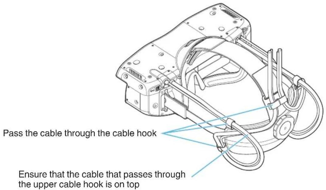
When cable is disconnected
If the cable is disconnected, follow the illustration below to connect it.
Connection
- The connection procedures differ according to the device used. For details, please refer to the instruction manual of the device to be connected.
- Some cables cannot be connected to this unit due to the size of their connector cover.
Connecting with a PC
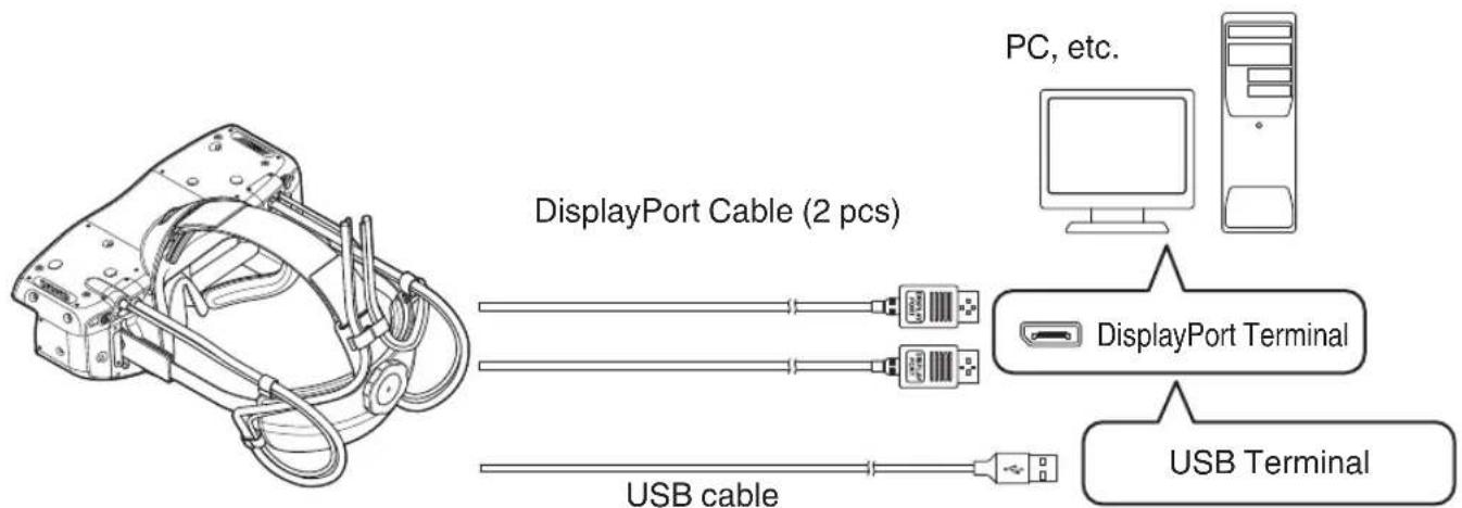
flowchart
graph TD
    A["DisplayPort Cable (2 pcs)"] --> B["PC, etc."]
    A --> C["DisplayPort Terminal"]
    A --> D["USB Terminal"]
    A --> E["USB cable"]
- Connect the two DisplayPort cables connected to this unit to the DisplayPort terminals of the PC.
- Connect the USB cable connected to this unit to the USB terminal of the PC.
*1 For more details on the recommended operating system requirements on the PC, please refer to "Specifications" (P. 38).
*2 When switching the system, do not connect a SteamVR Tracking System 2.0 equipment other than this unit to the USB terminal.
Doing so may damage the data on the equipment. (Refer to "Software" P. 22)
Connecting the Power Cord

① Connect the DC cable of the supplied AC adapter and the DC cable connected to this unit
② Connect the power cord to the AC adapter (use a power cord according to the environment in which the unit is used)
③ Insert the power plug into the wall outlet.

Precautions to prevent fire and electric shock
- When you are not using the HMD, please unplug the power cord from the outlet.
- Connect it using only the power cord supplied.
- Do not use a voltage other than the indicated power voltage.
- Do not damage, break or modify the power cord. Do not place a heavy object on the power cord, or heat or pull it. Doing so may damage the power cord.
- Do not unplug the power cord with wet hands.
Initial Configuration
1 Download and install the software programs
The following software programs are needed for the use of this unit.
• NVIDIA GeForce driver
Download and install NVIDIA GeForce Game Ready Driver 461.72 or a later version from the official NVIDIA website.
- Steam
Go to the official Steam website, click on "Install Steam" to download the setup file, followed by running the file and following the instructions on the screen to install the Steam software.
https://store.steampowered.com/
- SteamVR
Launch Steam and log in. Click on the Steam icon display in the task tray on the PC, and select SteamVR to install.
*1 To use SteamVR, you need to log in to Steam. Log in with an existing account, or do so after creating a new account.
*2 The URL link to the official Steam website and installation steps for Steam and SteamVR may be subject to changes.
• HMD-VS1W driver
Go to our website below to download and install the HMD-VS1W driver installer.
https://www3.jvckenwood.com/english/download/hmd-vs1w_software/
* The “IPD adjustment software” and “HMD configuration software” will also be installed together with the HMD-VS1W driver.
2 Connecting with a PC
Refer to "Connection" (P. 17) to connect the power cord. Connect this unit to the PC.
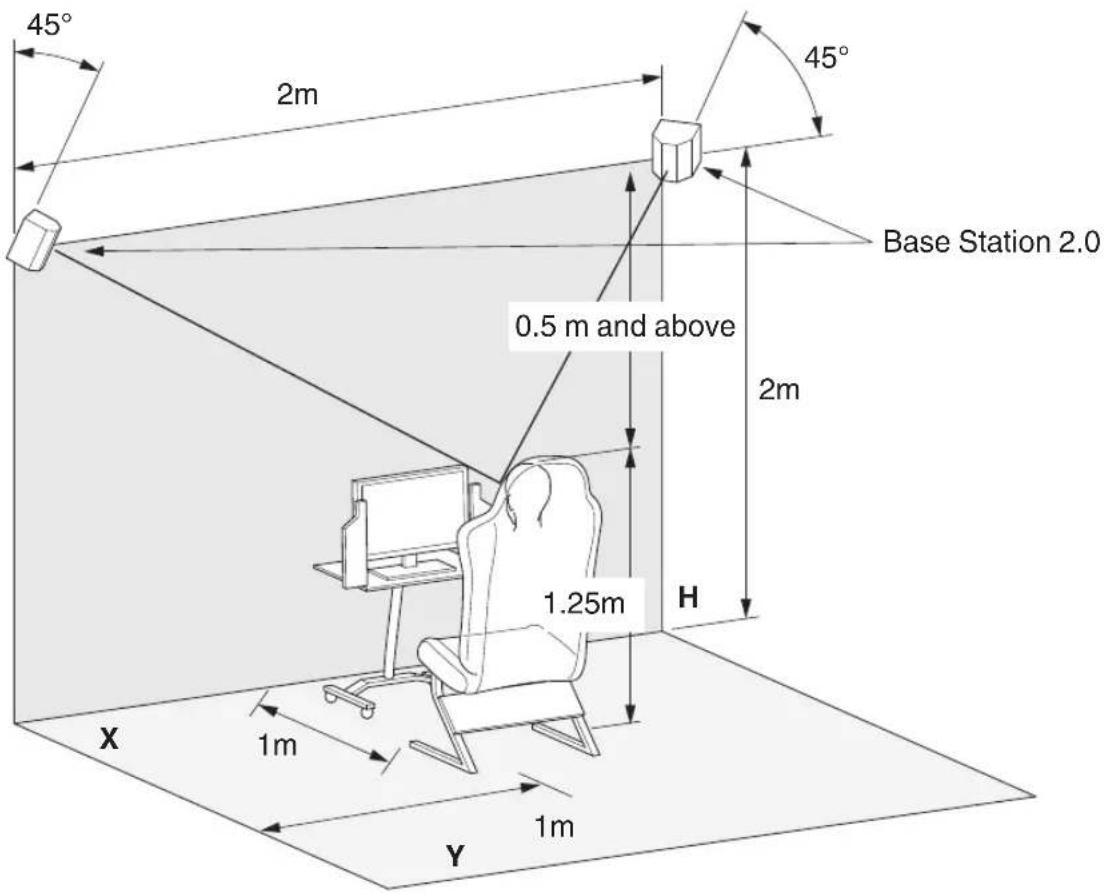
3 Installing SteamVR Base Station 2.0
As illustrated in the diagram below, install two SteamVR Base Station 2.0 units at a height of 2m and a distance of 2m from each other at the two corners in front of the space for using the system.
Use this unit at a seated position (height of approx. 1.25 m) that is 1 m away from the center of the two SteamVR Base Station 2.0 units.
* Ensure a height difference of at least 0.5 m between this unit and the SteamVR Base Station 2.0 units during use.
Viewing Videos
Initialization of the settings is needed before using this unit.
Before using this unit, refer to "Initial Configuration" (P. 18) to initialize the settings.
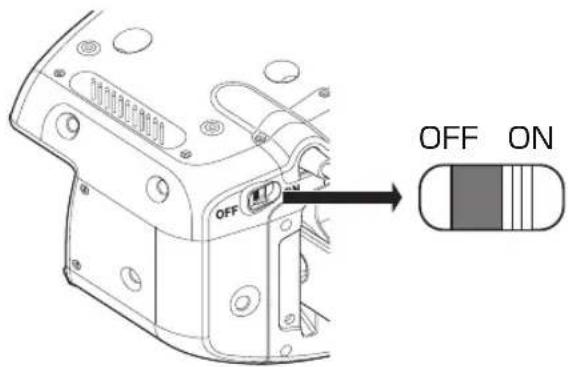
1 Turn on the power
Turn on the power switch of this unit.
2 Launch the SteamVR app
Room setup is needed during the first startup.
Upon launching the SteamVR app, a video image is displayed.
3 Adjust the volume level
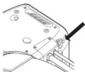
If you are using headphones or earphones, connect the unit to the audio output terminal, followed by adjusting the volume.
* This unit does not come with a volume control function. Adjust the volume on SteamVR.
① Set the volume output of SteamVR to 0
* The volume is configured to the maximum level in the default setting. Be careful of the volume when you are using headphones or earphones.
② Connecting the headphones/earphones
natural_image
Technical line drawing of a mechanical component with a tool inserted (no text or symbols)③ Adjust the volume output of SteamVR
4 Put on this unit
Refer to "Putting on" (P. 14) to put on this unit.
5 Turn off the power
After using, exit the SteamVR app before turning off the power switch.
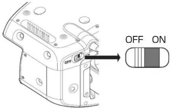
*1 Do not power on or off by disconnecting the AC adapter.
*2 To power on again after turning off the power, allow a time interval of at least 5 seconds before doing so.
*3 If the power of the unit is turned off or the AC adapter is disconnected while SteamVR is running, a message prompting you to restart the HMD-VS1W driver will appear on the PC screen.
About the Software
The IPD adjustment software and HMD configuration software will also be installed together with the HMD-VS1W driver. (Refer to P. 18 "Initial Settings")
Before using the software, make sure to refer to "Initial Settings" (P. 18) and initialize the settings.
IPD Adjustment Software
Below are the functions for adjusting the interpupillary distance (IPD).
Note that the image may appear out of focus or it may cause strain to the eyes if the IPD is not correctly set.
Measuring the IPD in advance and applying the measurements to the settings of the IPD adjustment software helps to deliver a more pleasant experience when using this product.
Use the IPD software after powering on this unit and launching SteamVR.
The IPD value cannot be adjusted if SteamVR is not running.
* There are different ways to measure the IPD, such as consulting an eye specialist or measuring using a ruler and mirror.

① IPD Value Reset Button
Resets the IPD value to the default value (64.0 mm).
② Exit Software Button
Exits the IPD adjustment software program.
③ IPD Value Display
Displays the current IPD value. (Adjustable range: 55 mm to 75 mm)
④ Offset Value +/- Display
Displays the amount of increase or decrease from the default value of 64.0 mm to the current IPD value.
⑤ IPD Decrease Button
Decreases the IPD value in 0.5 mm intervals.
⑥ IPD Increase Button
Increases the IPD value in 0.5 mm intervals.
HMD Configuration Software
Use the HMD configuration software after connecting this unit to a PC and turning on the power.
Brightness
Below are the functions for configuring the brightness.
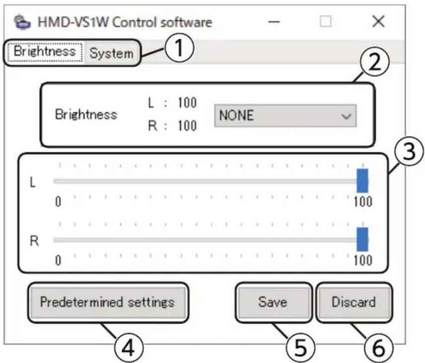
① Brightness/System Tab
For switching between Brightness and System.
② Brightness Settings Display/Preset Switching
Displays the brightness settings of the left and right panels on the head-mounted display. The preset values selected from the drop-down list are reflected in the head-mounted display. Press "Save" to apply the settings.
③ Brightness Settings Lever
For configuring the preset brightness values available for selection from the drop-down list. Selecting preset reflects the current brightness for L and R on the lever display.
④ Predetermined settings
For displaying a screen for configuring the name of the preset brightness. Up to 8 ASCII characters can be used for the name.
⑤ Save
Saves the displayed settings to the head-mounted display.
⑥ Discard
Discards the displayed settings and displays the current head-mounted display settings in the software program.
Predetermined settings
Below are the functions for configuring the name of the preset brightness.

For configuring the name for each of the presets from 1 to 4.
The brightness configured for each of the presets is displayed in the respective fields.
Pressing Set reflects the configured preset name.
System

⑧ Switch System
For configuring whether for this unit to recognize SteamVR as a head-mounted display (HMD) or as a controller. Pressing "Save" at the bottom reflects the settings.
* When switching between HMD/Controller, do not connect a SteamVR Tracking System 2.0 equipment other than this unit to the USB terminal. Doing so may damage the data on the equipment.
⑨ Switch Refresh Rate
For switching the refresh rate for the panel of the head-mounted display.
Pressing "Save" at the bottom reflects the settings.
* Do not switch the refresh rate while SteamVR is running.
If the refresh rate is changed, SteamVR needs to be rebooted for video images to be displayed.
⑩ Direct Mode ON/OFF
For switching Direct Mode to ON/OFF when using GPU (NVIDIA).
Pressing "Save" at the bottom reflects the settings.
* Direct Mode is a mode for the NVIDIA driver to recognize the VR headset not as a typical desktop monitor, but as a special display that allows access only by VR applications. Turn on the Direct Mode when using SteamVR. When using other VR apps, follow the instruction manual to configure the Direct Mode accordingly. To display Windows images on the HMD-VS1W/HMD-VS1DW, turn off the Direct Mode.
⑪ Information
Displays information on the head-mounted display.
⑫ Save
Saves the displayed settings to the head-mounted display.
⑬ Discard
Discards the displayed settings and displays the current head-mounted display settings in the software program.
Information

⑭ version
Displays the version of this software.
⑮ Serial number
Displays the serial number of this unit.
⑯ No. of startups
Displays the number of times the power of this unit has been turned on.
⑰ Illumination time
Displays the panel display time of this unit.
⑱ Firmware version
Displays the firmware version of this unit.
⑲ DP driver version left
Displays the firmware version of the IC (left) inside this unit.
⑳ DP driver version right
Displays the firmware version of the IC (right) inside this unit.
Servicing of the HMD Unit
• Always keep the product clean.
- Because lenses such as half mirrors are coated, rubbing with a hard object may cause scratches.
- If the product becomes dirty, follow the procedure below.
1) Blow off the dust on the surface
Use a manual pump-type air blower or a soft-bristle brush for lenses to remove dust on the surface.
Do not use a spray can type air duster. The gas may affect the performance of this product.
As with glasses, you don't have to worry about fine small dust.
2) Removing Contaminates
Use a clean, soft cloth or a lens cleaning cleaning paper lightly moistened with IPA (isopropyl alcohol) with a purity of 90% or higher.
When cleaning, wipe from the center to the outside with a light force. If you rub it too hard, it may be scratched.
- To replace the half-mirror, please contact our service center.
- Replace the consumable parts periodically.
- For purchase of consumable supplies, please consult our authorized dealer or customer service center.
Replacement of Consumable Parts
Forehead and Face Pads
- The forehead and face pads can be attached to this unit using a fastener. Lift the pad carefully at the edge of the soft portion to detach it from the unit. To attach a new forehead or face pad, press gently while ensuring that the fastener on the pad coincides with the fastener on the unit.

natural_image
Technical line drawing of a mechanical assembly showing internal components and motion arrows (no text or symbols)Rear Pad
- The rear pad can be attached to the rear cover unit using a double-sided tape. Lift the pad carefully at the edge of the soft portion to detach it from the unit. To attach a new rear pad, do so by pressing the rear pad gently while ensuring that it coincides with the contour of the rear cover unit.

Nose Pad
- The nose pad can be attached to this unit using a hook. Lift the pad carefully at the edge of the soft portion to detach it from the unit.
To attach a new nose pad, hook the protruded part of the nose pad to the hole on the unit.

natural_image
Technical line drawing of a mechanical component with internal channels and directional arrows indicating motion (no text or symbols)Adjustment Band
- To replace the adjustable band, do so after removing the forehead pad.
1 Turn the forehead adjustment dial counterclockwise to detach the forehead pad along with the base of the forehead pad.

natural_image
Technical line drawing of a mechanical component with a curved arrow indicating a force or adjustment (no text or symbols present)2 Detach the hook-and-loop fastener of the adjustment band and replace it.

natural_image
Technical diagram of a mechanical device with hoses and a belt, showing no text or symbols3 After attaching the new adjustment band, press the forehead pad and turn the forehead adjustment dial clockwise to attach it.

natural_image
Technical line drawing of a mechanical component with an arrow indicating rotation or movement (no text or symbols present)Protect Filter (HMD-VS1DW)
Removing the Protect Filter
1 Push the edge of the Protect Filter in the direction indicated by the arrow.
2 The Protect Filter will be raised. Pull the raised portion.
3 Perform the same steps for the opposite edge of the Protect Filter and the lock at the lower end will be disengaged.

Attaching the Protect Filter
1 Align the indentation on the Protect Filter with the protrusion on the main unit.
2 Bend the Protect Filter and insert both edges of it into the guide of the main unit.

3 Push the Protect Filter toward the lower lock.
4 Push the Protect Filter towards the upper two locks.

* When the Protect Filter is attached, you may see little reflected light from the combiner, but this is not malfunction.
| Parts Parts No. | |
| Face Pad G1D-0441-00 | |
| Forehead Pad G1D-0442-00 | |
| Nose Pad G1D-0443-00 | |
| Rear Pad G1D-0444-00 | |
| Adjustment Band J6B-0070-00 | |
| Protect Filter B1B-0258-00 |
Disinfection of Product
“Alcohol (ethanol) disinfectants” and “alcohol-type (ethanol) wet tissues” available commercially can be used if the following precautions are complied with.
- Do not wet the openings (external connection terminals, vents, etc.), gaps inside this unit and the interior face of the rear cover with disinfectants.
- Use disinfectants and wet tissues that do not contain chlorine or chlorine-based additives.
Penetration of chlorine or chlorine-based additives into this product may cause corrosion of the metallic parts and result in malfunction.
- Dampen a soft cloth or wet tissue with a small amount of disinfectant liquid such that it is not dripping from cloth or tissue, and use it to wipe the surface of the unit.
Do not spray disinfectants directly onto the product or immerse the unit in the disinfectant liquid. Doing so may cause the unit to malfunction.
- Do not power on the unit while it is still wet after wiping with the disinfectant. Doing so may cause the unit to malfunction.
- The sterilization or disinfection effect varies with the disinfectant or wet tissue in use. Before using, check with the seller or manufacturer of the disinfectant or wet tissue for more information.
- We do not guarantee the compatibility of this product with all types of disinfectants and wet tissues. Try out the disinfectant in advance at a less noticeable spot on this unit to check whether there is any abnormality after use. Note that in the event that the product is damaged or malfunction occurs as a result of alcohol disinfection, users shall be responsible for any costs incurred from the necessary repairs, including replacement of the parts.
- Do not wipe the printed parts. Doing so may cause the printed information to disappear or fade in color.
- When using a commercially available sterilizer, please check with the seller or manufacturer of the device for more information before using.
Note that in the event that the product is damaged or malfunction occurs as a result of the sterilizer, users shall be responsible for any costs incurred from the necessary repairs, including replacement of the parts.
Long-term Storage
- For prolonged storage of the unit at a place with an indoor temperature of 35^ C and humidity of 60% or higher, it is recommended that you keep it in an airtight bag together with desiccants.
- Replace the desiccants once a year. The desiccants will need to be replaced at shorter intervals if the storage environment is extremely humid.
* For more information on the desiccants and airtight bag to be used, please consult our authorized dealer or customer service center.
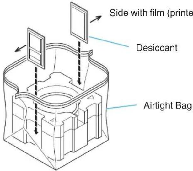
| Parts Parts No. | |
| Airtight Bag C43435-004A | |
| Desiccant LC43436-001A |
Troubleshooting
Power is not supplied
| Check Action | Reference Page | |
| Is the power cord disconnected? Insert the power cord (plug) properly. P. 17 |
Video image does not appear or appears distorted
| Check Action | Reference Page | |
| Is the power of the devices (PC, etc.) turned on? | Turn on the power of the devices (PC, etc.). P. 17 | |
| Are the devices (PC, etc.) properly connected? | Connect the devices (PC, etc.) properly. P. 17 | |
| Are the correct signals being output from the device (PC, etc.)? | Configure the devices (PC, etc.) correctly. P. 17 | |
| Does the PC meet the recommended operating system requirements? | Check the recommended operating system requirements for PCs. | P. 38 |
| Are the “HMD”/“Controller” settings correct? If | the video images are also using the resources of SteamVR, configure “System” to “HMD”. | P. 25 |
| Are the IDs for the two base stations correctly configured? | Configure the IDs (configure to different IDs) correctly. For more details, please refer to the instruction manual of SteamVR Base Station 2.0. | - |
| Are the Direct Mode settings correctly configured? | Turn on the Direct Mode when using SteamVR. When using other VR apps, follow the instruction manual to configure the Direct Mode accordingly. To display Windows images on the HMD-VS1W/HMD-VS1DW, turn off the Direct Mode. | P. 25 |
Video image is dark or blurry
| Check Action | Reference Page | |
| Is the half-mirror dirty? If dirt is attached to the surface of the half-mirror, wipe it off using a piece of dry and soft cloth. | P. 27 | |
| Are you wearing the unit correctly? Adjust the belt adjustment dial, forehead adjustment dial and adjustment band to wear the unit properly. | P. 14 |
No sound is heard
| Check Action | Reference Page | |
| Are the headphones correctly connected? Connect the headphones or earphones correctly to the audio output terminal. | P. 20 | |
| Are the correct signals being output from the device (PC, etc.)? | Configure the devices (PC, etc.) correctly. P. 17 | |
Unable to change the IPD value using the IPD adjustment software
| Check Action | Reference Page | |
| Is the power of the unit turned on? Turn on the power of the connected devices. P. 20 | ||
| Is SteamVR running? Start up SteamVR. P. 20 |
Use of Commands
It is possible to control this unit by connecting it to a PC using a USB cable.
Required environment
Windows10
Terminal software
1 Connect this equipment and PC with USB cable
For the first connection, the driver will be installed automatically. (For Windows10)
Make sure you have "USB Serial Device (COMx)" in "Ports (COM and LPT)" in Device Manager.
- “x” changes depending on the environment.
2 Start the terminal software
Connect to "USB serial device (COMx)" with any terminal software.
| Recommended settings | |
| Speed 115200 | |
| Data 8 bit | |
| Parity none | |
| Stop bit 1 bit | |
| Flow Control none | |
3 Use commands
You can operate this unit and acquire the status by entering commands on the terminal.
ex.
state [arg1]
[arg1] I Gets the status of the left panel.
r Gets the status of the right panel.
*1 "state" can be abbreviated as "st"
*2 Please leave a "space" between "state" and "arg1"
| Result Meaning | |
| STATE_NONE The power switch is off. | |
| STATE_WAITCABLE The power switch is ON and the DisplayPort cable is not connected. | |
| STATE_CONNECTING The DisplayPort cable is connected and waiting for the connection to stabilize. | |
| STATE_NORMAL The connection with the DisplayPort cable is stable. |
List of Commands
* r...Right panel operation, l...Left panel operation
| Command | Abbreviation | arg1 arg2 arg3 arg4 Output Description | |||||
| state st r/l | --- | STATE_NONE STATE_WAITCABLE STATE_CONNECTING STATE_NORMAL | You can get the status of each panel. STATE_NONE: The power switch is off. STATE_WAITCABLE: The power switch is ON and the DisplayPort cable is not connected. STATE_CONNECTING: The DisplayPort cable is connected and waiting for the connection to stabilize. STATE_NORMAL: The connection with the DisplayPort cable is stable. | ||||
| framerate fr | ----60/72 Shows the current refresh rate settings. | ||||||
| 60/72----Change the refresh rate settings. | |||||||
| directmode | dm | ----off/on | Shows the current NVIDIA Direct Mode settings. off: Direct Mode Off on: Direct Mode On | ||||
| on/off---- | Change the NVIDIA Direct Mode settings. off: Direct Mode Off on: Direct Mode On | ||||||
| time tm | --- | 12h34m | Displays the panel display time. Over 60,000 hours will be displayed as 60000h+. | ||||
| count | cnt | - | - | - | - | 123 | Displays the number of times the power is turned on. It is displayed as 5000000+ after 5 million times. |
| version | ver | - | - | - | - | ver.0.0.0 | Displays the HMD-VS1W/HMD-VS1DW firmware version. |
| name | nm | - | - | - | - | HMD-VS1W/HMD-VS1DW | Displays the product name. |
| serialnumber | sn | - | - | - | - | 00000000 | Shows the serial number. |
| brightness br | - | - | - | - | l:100 r:100 | Displays the brightness. | |
| (NONE)/l/r | 0 - 100/+/-- | -- | Change the brightness. You can specify the brightness by entering a numerical value (0 to 100). You can increase / decrease the brightness by 1 with +/- Perform the same operation on the left and right without specifying l / r. | ||||
| preset pr | None | - | - | - | 0 - 4 | Displays the preset number being set. | |
| all/now | - | -- | num:NUM br_L: 0 - 100 br_R: 0 - 100 Name:NAME | Displays preset information. all:View information for all presets. now: Display information about presets being set. | |||
| num | l/r/n/all | num:NUM br_L: 0 - 100 br_R: 0 - 100 Name:NAME | Display the preset specified by the argument "num" (1-4). l: Left panel brightness is displayed. r:Left panel brightness is displayed. n:Display preset name. all:Show all of the above. | ||||
| num | 0 - 100 | 0 - 100 | NAME | None | Sets the preset specified by the argument "num" (1-4). arg2: Brightness (left) arg3: Brightness (right) arg4: Preset name | ||
| ocm | None | (NONE)/l/r | - | - | - | - | Displays the firmware version of the DP-mipi conversion chip. Show both panels without l or r. |
| reset | rst---- Initialize preset settings, refresh rate, and Direct Mode set | ||||||
| dfu | - | - | - | - | - | - | Reboots in the DFU Mode (mode for updates). |
| powerswitch | pwrsw | - | - | - | - | Off/On | Indicates the status of the power switch (Off/On). |
| power | pwr | -- | -- | off/on indicates the status of the power | (Off/On). | ||
| on/off - | -- | - For switching the power to On/Off. | |||||
Specifications
| Product Name Head Mounted Display | ||
| Model Name HMD-VS1W, HMD-VS1DW | ||
| Display Device/Resolution 5.5", 2560 × 1440 × 2 | ||
| Refresh Rate 60 Hz / 72 Hz | ||
| Color Gamut sRGB 100% (area ratio) | ||
| Optical System Half-mirror + Combiner | ||
| Angle of View H: 120° V: 45° (V: 72° with open view) | ||
| Interpupillary Distance Adjustable using IPD adjustment software | ||
| Input Compatibility Signal 1440×2560(WQHD) 60Hz/72Hz | ||
| Input/Output | Video/Audio Input Terminal | PC: DisplayPort 1.2 × 2 (Supports HDCP2.2) |
| Audio Output Terminal S | Stereo mini plug x 1 | |
| Control Terminal PC: USB 2.0 (USB Type-A) × 1 | ||
| Cable Length 3 m (DisplayPort, USB, power cable bundled) | ||
| Power Requirements | AC 100 to 240 V, 50/60 Hz (AC adapter) | |
| DC 12 V (Main Unit) | ||
| Power Consumption 6 W | ||
| Operation/Storage Environment | Allowable Operating Temperature Range | 0 °C to +35 °C |
| Allowable Storage Temperature Range | -15 °C to +70 °C | |
| Allowable Relative Humidity Range | 20 % to 80 % | |
| External Dimensions (W x D x H) 280 x 135 x 134 mm (excluding head band and cable) | ||
| Mass | HMD-VS1W640 g (excluding head band and cable)1270 g (including head band and cable)HMD-VS1DW690 g (excluding head band and cable)1320 g (including head band and cable) | |
| Accessories Refer to P. 3. | ||
| Recommended Operating System Requirements for PC | |
| CPU | Intel Core i9 9900K or higher |
| GPU | NVIDIA GeForce RTX 2080 or RTX 3070 (or higher) |
| Memory | 32 GB and above |
| Video Output | DisplayPort 1.2 (or higher) × 2 |
| USB Port | USB 2.0 or higher x 1 |
| OS | Windows 10 64-bit |
- Design and specifications are subject to change without prior notice.
- Please note that some of the pictures and illustrations may have been abridged, enlarged or contextualized in order to aid comprehension. Images may differ from the actual product.
- Fine black spots may be seen on the outer surface of the half-mirror. These do not have any impact on the video images during actual use.
- The display device is manufactured using extremely high-precision technology with a pixel effectiveness of 99.99% . Only 0.01% or less of the pixels are either missing or would remain permanently lit.
About Trademarks and Copyrights
Intel and Intel Core are trademarks of Intel Corporation in the United States and/or other countries.
NVIDIA and GeForce RTX are trademarks or registered trademarks of NVIDIA Corporation.
HTC Vive is a trademark or registered trademark of HTC Corporation.
Steam and SteamVR are trademarks of Valve Corporation in the United States and/or other countries.
Windows is a trademark of Microsoft Corporation in the United States.
The name of the other products are trademarks or registered trademarks of the respective companies.
Index
A AC adapter....3
Accessories....3
Adjust the volume level....20
Adjustment Band.... 13
Airtight Bag....33
Audio Output Terminal....13
B Belt Adjustment Dial.... 13
Brightness....23
Brightness - Discard.... 23
Brightness - Save.... 23
Brightness Settings Display/Preset Switching..... 23
Brightness Settings Lever....23
Brightness/System Tab.... 23
C Cable....12
Cable Hook.... 13
Connecting the Power Cord.... 17
Connecting with a PC.... 17
Connection.... 17
D Desiccant.... 33
Direct Mode ON/OFF 25
Disinfection of Product.... 32
DisplayPort cable.... 17
DisplayPort Terminal.... 17
Download and install the software programs.... 18
DP driver version left.... 26
DP driver version right.... 26
E Exit Software Button.... 22
F Face Pad.... 13
Firmware Update Button....13
Firmware version.... 26
Forehead Adjustment Dial.... 13
Forehead Pad....13
H Half-mirror.... 12
HMD Configuration Software....23
HMD-VS1W driver....18
I If you are wearing glasses.... 16
Illumination time....26
Information.... 25, 26
Initial Configuration....18
Installing SteamVR Base Station 2.0....19
IPD Adjustment Software....22
IPD Decrease Button....22
IPD Increase Button....22
IPD Value Display....22
IPD Value Reset Button....22
L Launch the SteamVR app....20
List of Commands.... 37
Long-term Storage.... 33
N No. of startups....26
Nose Pad....13
NVIDIA GeForce driver....18
O Offset Value +/- Display....22
P Power Cord....3
Power Switch....13
Predetermined settings....23, 24
Preset Name Settings....24
Protect Filter.... 30
Put on this unit.... 21
Putting on the Head-mounted Display.... 14
R Rear Cover.... 13
Rear Pad.... 12
Recommended Operating System Requirements for PC....38
Replacement of Adjustment Band.... 29
Replacement of Consumable Parts.... 28
Replacement of Face Pad.... 28
Replacement of Forehead Pad....28
Replacement of Nose Pad....29
Replacement of Rear Pad.... 28
S Sensor Cover.... 12
Sensor Unit....13
Serial number.... 26
Servicing of the HMD Unit.... 27
Side Belt....13
Smoke Panel.... 12
Specifications.... 38
Steam....18
SteamVR.... 18
SteamVR Base Station 2.0....19
Switch Refresh Rate....25
Switch System....25
System.... 25
System - Discard.... 25
System - Save.... 25
T Troubleshooting.... 34
Turn off the power.... 21
Turn on the power....20
U USB cable.... 17
USB Terminal.... 17
Use of Commands....36
V version....26
Viewing Videos....20
W When cable is disconnected....16
HMD-VS1W/HMD-VS1DW Head Mounted Display


- For Customer use :
- Contents
- Getting Started
- Set up
- Operate
- Adjust/Set
- Maintenance
- Troubleshooting
- Others
- Accessories
- Check the Accessories
- Safety Precautions
- Important Safety Instructions
- ATTENTION
- ATTENTION:
- NOTES:
- Precautions
- Power Supply
- AC Adapter
- Installation Environment
- Operation Environment
- Health Concerns
- CAUTION:
- Dear Customer
- Information for Users on Disposal of Old Equipment and Batteries
- [European Union only]
- FRANÇAIS
- Rear
- Putting on
- Precautions during Use
- Putting on the Head-mounted Display
- MEMO
- When cable is disconnected
- Connection
- Connecting with a PC
- Connecting the Power Cord
- Precautions to prevent fire and electric shock
- Initial Configuration
- Download and install the software programs
- Connecting with a PC
- Installing SteamVR Base Station 2.0
- Viewing Videos
- Turn on the power
- Launch the SteamVR app
- Adjust the volume level
- Put on this unit
- Turn off the power
- About the Software
- IPD Adjustment Software
- HMD Configuration Software
- Brightness
- Predetermined settings
- System
- ⑧ Switch System
- ⑨ Switch Refresh Rate
- ⑩ Direct Mode ON/OFF
- ⑪ Information
- ⑫ Save
- ⑬ Discard
- Information
- Servicing of the HMD Unit
- Replacement of Consumable Parts
- Forehead and Face Pads
- Rear Pad
- Nose Pad
- Adjustment Band
- Protect Filter (HMD-VS1DW)
- Removing the Protect Filter
- Attaching the Protect Filter
- Disinfection of Product
- Long-term Storage
- Use of Commands
- Connect this equipment and PC with USB cable
- Start the terminal software
- Use commands
- List of Commands
- Specifications
- About Trademarks and Copyrights
- Index
Brand : JVC
Model : HMD-VS1W
Category : Headphones