
VF-HP900 - Headphones JVC - Free user manual and instructions
Find the device manual for free VF-HP900 JVC in PDF.

| Product type | Headphones |
| Brand | JVC |
| Model | VF-HP900 |
| Coupling type | Wired (estimated) |
| Form factor | Over-ear (estimated) |
| Dimensions (approx.) | 20 x 15 x 8 cm (estimated) |
| Weight (approx.) | 250 g (estimated) |
| Power supply | None (passive, powered by audio source) |
| Connection | 3.5 mm jack (estimated) |
| Impedance (estimated) | 32 Ω |
| Sensitivity (estimated) | 100 dB/mW |
| Frequency response (estimated) | 20 Hz - 20 kHz |
| Main functions | Stereo audio listening, listening comfort |
| Maintenance and cleaning | Clean with a dry cloth, do not use liquids |
| Safety | Do not expose to water or moisture; do not use at excessive volume to protect hearing |
| Included accessories (estimated) | Audio cable, airline adapter (estimated) |
| Spare parts and repairability | Contact JVC after-sales service for any repairs |
| General information | Manufactured by JVCKENWOOD Corporation, Japan; compliant with FCC standards |
Frequently Asked Questions - VF-HP900 JVC
User questions about VF-HP900 JVC
0 question about this device. Answer the ones you know or ask your own.
Ask a new question about this device
Download the instructions for your Headphones in PDF format for free! Find your manual VF-HP900 - JVC and take your electronic device back in hand. On this page are published all the documents necessary for the use of your device. VF-HP900 by JVC.
USER MANUAL VF-HP900 JVC
natural_image
Line drawing of a portable electronic device with control knobs and a screen (no text or symbols)HDMI ^TM
HIGH-DEFINITION MULTIMEDIA INTERFACE
About INSTRUCTIONS
Please view INSTRUCTIONS from the URL link below.
North America:
http://pro.jvc.com/prof/attributes/features.jsp?model_id=MDL102617
Europe:
http://www.jvc.net
China:
http://www32.jvckenwood.com/jvc/manual_e/index.asp?
Please read the following before getting started:
Thank you for purchasing this product. Before operating this unit, please read the instructions carefully to ensure the best possible performance.
For Customer Use:
Enter below the Serial No. which is located on the body.
Retain this information for future reference.
Model No. VF-HP900G
Serial No.
Safety Precautions
FOR USA
These are general Important Safety Instructions and certain items may not apply to all appliances.
Important Safety Instructions
- Read these instructions.
- Keep these instructions.
- Heed all warnings.
- Follow all instructions.
- Do not use this apparatus near water.
-
Clean only with dry cloth.
-
Do not block any ventilation openings. Install in accordance with the manufacturer's instructions.
-
Do not install near any heat sources such as radiators, heat registers, stoves, or other apparatus (including amplifiers) that produce heat.
-
Protect the power cord from being walked on or pinched particularly at plugs, convenience receptacles, and the point where they exit from the apparatus.
-
Only use attachments/accessories specified by the manufacturer.
-
Use only with the cart, stand, tripod, bracket, or table specified by the manufacturer, or sold with the apparatus. When a cart is used, use caution when moving the cart/apparatus combination to avoid injury from tip-over.
-
Unplug this apparatus during lightning storms or when unused for long periods of time.
-
Refer all servicing to qualified service personnel. Servicing is required when the apparatus has been damaged in any way, such as power-supply cord or plug is damaged, liquid has been spilled or objects have fallen into the apparatus, the apparatus has been exposed to rain or moisture, does not operate normally, or has been dropped.

natural_image
Silhouette of a person climbing a ladder inside a circle (no text or symbols)POUR LES ÉTATS-UNIS
natural_image
Silhouette of a person climbing a ladder inside a circle with a diagonal line (no text or symbols)FOR USA AND CANADA
CAUTION
RISK OF ELECTRIC SHOCK
DO NOT OPEN

CAUTION:
TO REDUCE THE RISK OF ELECTRIC SHOCK. DO NOT REMOVE COVER (OR BACK).
NO USER-SERVICEABLE PARTS INSIDE. REFER SERVICING TO QUALIFIED SERVICE PERSONNEL.
The lightning flash with arrowhead symbol, within an equilateral triangle is intended to alert the user to the presence of uninsulated “dangerous voltage” within the product’s enclosure that may be of sufficient magnitude to constitute a risk of electric shock to persons.

The exclamation point within an equilateral triangle is intended to alert the user to the presence of important operating and maintenance (servicing) instructions in the literature accompanying the appliance.
POUR CANADA
ATTENTION
RISQUE D'ELECTROCUTION NE PAS OUVRIR

ATTENTION:
POUR EVITER TOUT RISQUE D'ELECTROCUTION NE PAS OUVRIR LE BOITER. AUCUNE PIECE INTERIEURE N'EST A REGLER PAR L'UTILISATEUR. SE REFERER A UN AGENT QUALIFIE EN CAS DE PROBLEME.

Supplier's Declaration of Conformity
Model Number: VF-HP900G
Trade Name: JVC
Responsible JVCKENWOOD USA
party: Corporation
Address: 500 Valley Road,
Suite 203 Wayne,
NJ 07470
Telephone 973-317-5000
Number:
This device complies with Part 15 of the FCC Rules. Operation is subject to the following two conditions: (1) This device may not cause harmful interference, and (2) this device must accept any interference received, including interference that may cause undesired operation.
Changes or modifications not approved by JVC could void the user's authority to operate the equipment. This equipment has been tested and found to comply with the limits for a Class A digital device, pursuant to Part 15 of the FCC Rules. These limits are designed to provide reasonable protection against harmful interference when the equipment is operated in a commercial environment.
This equipment generates, uses, and can radiate radio frequency energy and, if not installed and used in accordance with the instructions, may cause harmful interference to radio communications. Operation of this equipment in a residential area is likely to cause harmful interference in which case the user will be required to correct the interference at his own expense.
responsible : Corporation
Adresse : 500 Valley Road, Suite 203 Wayne, NJ 07470
The mains plug shall remain readily operable.
- Remove the mains plug immediately if the product functions abnormally.
WARNING: TO PREVENT FIRE OR SHOCK HAZARD, DO NOT EXPOSE THIS UNIT TO RAIN OR MOISTURE.
When the equipment is installed in a cabinet or on a shelf, make sure that it has sufficient space on all sides to allow for ventilation (10 cm (3-15/16") or more on both sides, on top and at the rear). Do not block the ventilation holes. (If the ventilation holes are blocked by a newspaper, or cloth etc. the heat may not be able to get out.) No naked flame sources, such as lighted candles, should be placed on the apparatus.
NOTES:
- The rating plate and safety caution are on the bottom and/or the back of the main unit.
- The serial number plate is on the bottom of the unit.
The apparatus shall not be exposed to dripping or splashing and that no objects filled with liquids, such as vases, shall be placed on the apparatus.
Attention:
To prevent shock, do not open the cabinet. No user serviceable parts inside. Refer servicing to qualified personnel.
WARNING
Operation of this equipment in a residential environment could cause radio interference.
CAUTION:
Where there are strong electromagnetic waves or magnetism, for example near a radio or TV transmitter, transformer, motor, etc., the picture and the sound may be disturbed. In such case, please keep the apparatus away from the sources of the disturbance.
The plastics packaging bags may cause suffocation when they are covered over the head. Tear them open, and keep them away from the reach of infants and children by ensuring that they are disposed of properly.
Dear Customer
This apparatus is in conformance with the valid European directives and standards regarding electromagnetic compatibility and electrical safety. European representative of JVCKENWOOD Corporation is: JVCKENWOOD Deutschland GmbH Konrad-Adenauer-Allee 1-11 61118 Bad Vilbel GERMANY
Safety Precautions 3
Contents 8
Precautions for Proper Use 9
Names of Parts 10
Preparations
Connecting the VF Cable 12
Attaching the Protective Cover 13
Attaching the Number Plate 13
Attaching the Shoe Mount 13
Menu
Operating the Viewfinder Menus 14
Operating the Camera Menus 14
Configuring Shortcuts (Function Button) ..... 15
Configuration Method 15
Shortcut Menus for Auxiliary Features (F1 to F4) 15
Shortcut Menus for Picture Quality and Volume (F5 to F7) 15
Viewfinder Menu Flow Chart 15
List of Viewfinder Menus 16
Others
Troubleshooting 20
Specifications 20
Available Signal Formats 22
Symbols used
Caution : Describes precautions concerning the operation of this product.
Memo : Describes reference information, such as functions and usage restrictions of this product.
: Indicates the reference page numbers and reference items.

Content of this manual
- All rights reserved by JVCKENWOOD Corporation. Unauthorized duplication or reprinting of this manual, in whole or in part, is strictly prohibited.
- Illustrated designs, specifications and other contents of this manual are subject to change for improvement without prior notice.
- Other product and company names included in this instruction manual are trademarks and/or registered trademarks of their respective companies. Marks such as ^TM and ^® have been omitted in this manual.
Precautions for Proper Use
This unit is compatible with the GY-HC900 series. For information on other compatible models, please consult your dealer.
Please also read the instruction manual of the camera to be connected before using.
This is not a drip-proof product.
Before making use of this product, fasten it securely using a fitting tool (commercially available bracket, studio kit or the supplied shoe mount).
Location of Storage and Use
- Do not place this product at the following locations. Doing so may cause the product to malfunction or break down.
- Hot or cold places beyond the allowable operating temperature range of 0 °C to +40 °C (32 °F to 104 °F).
- Humid places beyond the allowable humidity range of 30 % RH to 80 % RH (non-condensing).
- Places in the vicinity of a strong magnetic field, such as near transformers or motors.
- Near equipment that emit radio waves, such as transceivers or mobile phones.
- Places that are subject to dust or sand.
- Places that are subject to strong vibrations.
- Places that are susceptible to condensation, such as near windows.
- Places that are subject to vapor or oil, such as kitchens.
- Places that emit radioactive rays or X-rays, and corrosive gases.
- Noise may occur in the images or the colors may change when this product and its connecting wire are used in places subjected to strong radio or magnetic waves (e.g., near radios, TVs, transformers, or monitors).
Handling the Product
- Insufficient ventilation may result in malfunction of this product. Make sure that objects placed around this product do not obstruct its ventilation.
- Do not place containers filled with water (vases, plants, cups, cosmetics, drugs and so on) on top of this product.
Water getting into the interior of the equipment may result in fire and electric shock.
Moving the Product
Remove connecting cables before moving this product.
When moving this product, do so after turning off the power of the connecting camera, and make sure to unplug the cable from this product. Failure to do so may damage the cable, causing fire or electric shock.
Maintenance
- Turn off the power of the connecting camera before performing maintenance of this product.
- Use a soft cloth to wipe the product. Do not wipe using thinner or benzene, as doing so may cause the surface to melt or turn cloudy. When there is significant soiling, wipe using a cloth by dipping it in a neutral detergent that is diluted with water, followed by cleaning using a dry cloth.
- The exterior of this product may change or the paint may fall off when come into contact with rubber or vinyl products for a prolonged period of time.
Energy Conservation
When this product is not used for a prolonged period of time, turn off the power of the system for safety and energy conservation purposes.
LCD Screen
Leaving the LCD screen exposed to the sun will damage the LCD screen. Do not place the product outdoors or near a window.
Do not scratch or press hard on the LCD screen, or place objects on top of the screen. Blotches may appear on the screen and lead to malfunction of the LCD panel.
When using the product in cold places, horizontal stripes and trailing images may appear or the screen may appear dark.
These are not malfunctions. The screen will appear normal again when the temperature rises.
Continuous display of still images may cause residual images.
The screen will return to normal after some time.
When the product is in use, the screen or cabinet may become warm. This is not a malfunction.
Bright/Dark Spots
Bright spots (red, blue or green) and dark spots that are continuously lit up may appear on the screen. An LCD panel is manufactured with extremely precise technology. Although it consists of more than 99.99% effective pixels, it may exhibit a very small number of continuous bright or dark spots on the screen.
Maintaining the LCD Screen
The surface of an LCD screen is specially treated to control reflections off the surface. Improper maintenance may affect the performance of the screen. As such, please adhere to the following points.
- Use a soft cloth such as a cleaning cloth or spectacles cleaning cloth to lightly wipe off any dirt on the surface of the screen.
- When there is significant soiling, wipe using a soft cloth such as a cleaning cloth or spectacles cleaning cloth soaked with a bit of water.
- Do not use alcohol, benzene, thinner, acidic, alkaline or abrasive cleaning fluid, or chemical wiping cloth to clean the screen as they will scratch the surface.
Disposal
Do not dispose this product with other normal waste products.
Do not throw the monitor into the rubbish that will be sent to the dumping-ground.
Names of Parts
Front
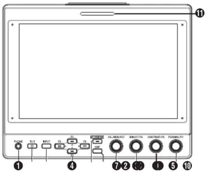
① [PHONE] Terminal
Outputs stereo audio.
Memo :
- When the [INPUT] button is set to "SDI" or "Camera", audio configured in [Audio Ch] is output.
② [⏻/l] (Standby) Button
Switches the viewfinder to on or off (standby).
- Green: Power on
• Orange: Power off (standby)
③ [INPUT] Button
For selecting an input.
- Camera: [VF CABLE] terminal
- SDI: [SDI IN] terminal
• HDMI: [HDMI] terminal
④ [▲/F1], [◀/F2], [▼/F3], [▶/F4] Buttons
- Can be used to operate the camera menu while it is being displayed.
- Pressing one of the buttons on the normal screen enables operation of the functions that are preconfigured in the function menu.
- To configure the function menu, press and hold down the button.
( P15 [Configuring Shortcuts (Function Button)] )
Memo :
- The LED is lit when the preconfigured feature is enabled. The LED does not light up when the function is disabled.
⑤ [CAMERA MENU] Button
Pressing the button displays the menu of the connected camera. For more details on the camera menu, refer to the instruction manual of the camera.
Memo :
- When the camera menu is active, the LED for the CAMERA MENU button lights up.
⑥ [EXIT] Button
Pressing the button in the viewfinder menu or camera menu moves the display to the menu at the next higher level. Pressing the button when the menu is at the highest hierarchical level returns the display to the normal screen.
⑦ [VOL./MENU/SET] Knob (Button)
For adjusting the volume level and operating or configuring the menus.
- Turning the knob in the clockwise or anti-clockwise direction on the normal screen displays the audio control menu screen and enables adjustment of the volume.
- Pressing the knob (button) on the normal screen displays the viewfinder menu screen.
- Turning the knob to the clockwise or anti-clockwise direction in the viewfinder menu moves the cursor (X) up or down.
Pressing the knob (button) confirms the selected item. If there are menus at the next lower hierarchical level, pressing the knob (button) moves to the menu at the lower level.
Memo :
- Configuring [Function]→[Scan] in the viewfinder menu to "Zoom" disables volume adjustment on the normal screen and switches to the mode for adjusting the Zoom position. Press the knob to alternate between adjustment of the vertical and horizontal positions.
⑧ [BRIGHT/F5] Knob (Button)
For adjusting the brightness of the viewfinder.
Memo :
- Pressing and holding down the knob (button) on the normal screen enables configuration of features in the function menu.
(P) P15 [Configuring Shortcuts (Function Button)]
⑨ [CONTRAST/F6] Knob (Button)
For adjusting the contrast of the viewfinder.
Memo :
- Pressing and holding down the knob (button) on the normal screen enables configuration of features in the function menu.
( P15 [Configuring Shortcuts (Function Button)] )
⑩ [PEAKING/F7] Knob (Button)
For adjusting the outline of the viewfinder.
Memo :
- Pressing and holding down the knob (button) on the normal screen enables configuration of features in the function menu.
(P) P15 [Configuring Shortcuts (Function Button)]
11 SMALL TALLY Lamp
The tally lamp lights up according to the settings of the camera menu.
- For GY-HC900 series, the tally lamp lights up according to the [System]→[Front Tally] settings of the camera menu.
Memo :
- Brightness of the tally lamp can be configured in [System]→[Small Tally].
(P19 [ Small Tally ] )
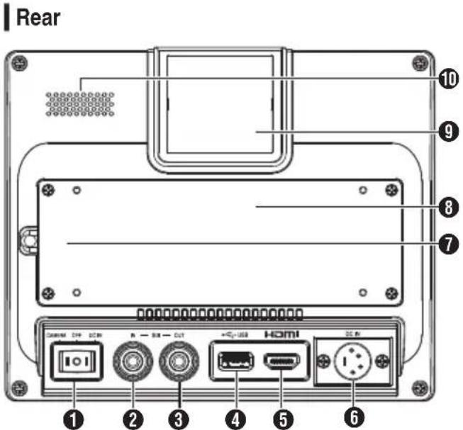
① Power Switch
- I[DC IN]: Receives power supply from the [DC IN] terminal
- O[OFF]: Switches off the power supply completely
- II [CAMERA]: Receives power supply from the VF cable
② [SDI IN] Terminal
Input terminal for 3G/HD/SD SDI signals.
Memo :
• Supports embedded audio signals.
③ [SDI OUT] Terminal
Output terminal for 3G/HD/SD SDI signals.
Memo :
- When power is turned on, signal from the [SDI IN] terminal is passed through, and outputs the reclocked signal from the [SDI OUT] terminal regardless of the state of the [INPUT] button. On-screen display (OSD) is not output in this case.
④ [USB] Terminal
For connecting the USB device for loading the "3D-LUT" file.
Memo :
Compatible USB device
• USB specification: USB2.0
- File system: FAT32
• Maximum capacity supported: 16 GB
Before using, format the USB device with a FAT32 file system.
⑤ [HDMI] Input Terminal
Input terminal for HDCP-compatible HDMI signals.
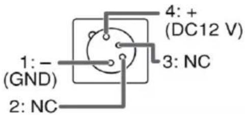
⑥ [DC IN] Terminal (XLR type, 4-pin)
Input terminal for DC 12 V power supply (max. DC 17 V).
Memo :
- If this unit is connected to a camera via a VF cable, there is no need to supply power from the [DC IN] terminal.
⑦ [VF CABLE] Terminal
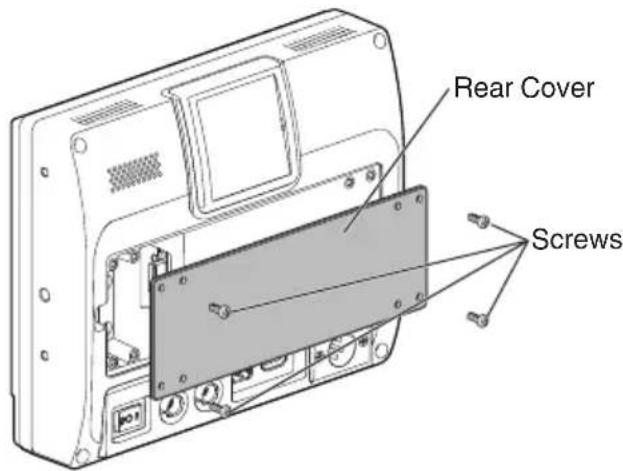
To connect a VF cable, remove the rear cover.
(☐ P12 [Connecting the VF Cable])
8 Rear Cover
Be sure to use this unit with the rear cover attached.
9 LARGE TALLY Lamp
The tally lamp lights up according to the settings of the camera menu.
- For GY-HC900 series, the tally lamp lights up according to the [System]→[Front Tally] settings of the camera menu.
Memo :
- Brightness of the tally lamp can be configured in [System]→[Large Tally].
(P19 [ Large Tally ] )
⑩ Speaker (Monaural)
Outputs mixed audio.
Memo :
- When the [INPUT] button is set to "SDI" or "Camera", audio configured in [Audio Ch] is output.
Connecting the VF Cable
To connect a VF cable, do so after turning off the power switch on the camera unit.
Connect the [VF CABLE] terminal of the viewfinder to the [VF] terminal of the camera using the supplied VF cable.
1 Unfasten the 4 screws to remove the rear cover
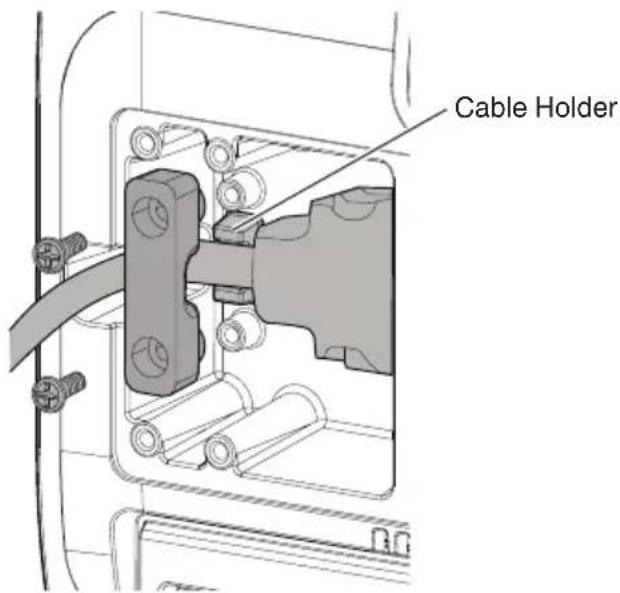
2 Unfasten the 2 screws to remove the cable clamp
![Cable Clamp [VF CABLE] Terminal Screws](/content/2026/06/1204623/images/be3ddf90b501a732de8c6d8e9d85bceb241bb967176b31b7104dd1a0e357771e.jpg)
3 Plug the supplied VF cable firmly into the [VF CABLE] terminal
![VF Cable [VF CABLE] Terminal](/content/2026/06/1204623/images/83d09de237423ac41381b64f24fe7e0bad856b4a53091af1a854bd2f52dcd095.jpg)
Memo :
- Pay attention to the orientation of the VF cable connector when plugging in.
4 Fit the VF cable into the groove of the cable holder and attach the cable clamp with the 2 screws
5 Be sure to mount the rear cover with the 4 screws
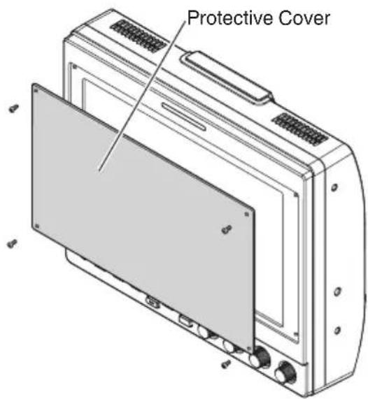
Attaching the Protective Cover
A protective cover can also be mounted if screen protection is needed.
1 Mount the protective cover with the 4 M2 screws supplied
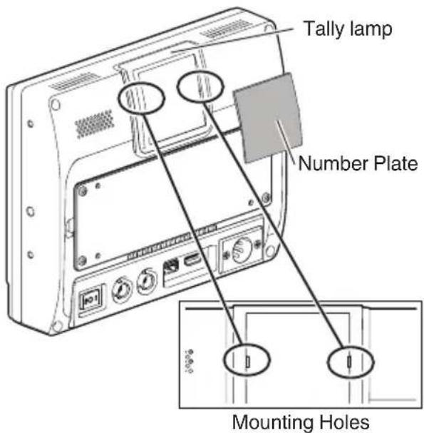
Attaching the Number Plate
Indicating a number on the number plate eases identification using the monitor number.
1 Fit the tabs of the number plate into the mounting hole of the tally lamp
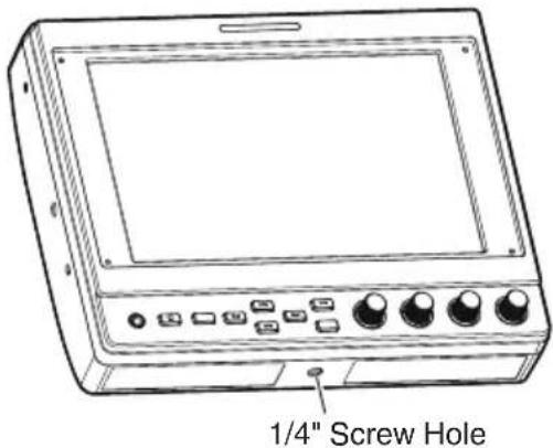
Attaching the Shoe Mount
The supplied shoe mount can be mounted to the 1/4" screw hole located on the bottom surface of this unit.
Before configuring the function settings, ensure that the terminals are correctly connected.
Operating the Viewfinder Menus
1 Press the [VOL./MENU/SET] knob (button) Viewfinder menu is displayed.
2 Move the cursor to the item to configure and press the [VOL./MENU/SET] knob (button)
- Pressing the button displays the item for configuration.
- Turn the knob to move the cursor up or down.
- If there is a menu at the lower hierarchical level, pressing the button moves to the menu at the next lower level.
- To return to the menu at the next higher hierarchical level, press the [EXIT] button to move up to the next level.
3 Turn the [VOL./MENU/SET] knob (button) to adjust the setting
4 Press the [VOL./MENU/SET] knob (button) to confirm the setting
5 Exit menu operation Pressing the [EXIT] button in the menu at the highest hierarchical level displays the normal screen.
Operating the Camera Menus
The camera menu can be operated when this unit is connected to a camera via a VF cable. For more details on the camera menu, refer to the instruction manual of the camera.
1 Press the [CAMERA MENU] button Displays the menu of the connected camera.
2 Move the cursor to the item to configure and press the [▶/F4] button or [VOL./MENU/SET] knob (button)
- Pressing the button displays the item for configuration.
- The [▲/F1], [◀/F2], [▼/F3], and [▶/F4] buttons can be used to move between menus at different hierarchical levels.
- To return to the menu at the next higher hierarchical level, press the [EXIT] button to move up to the next level.
3 Press the [▲/F1] or [▼/F3] button to adjust the setting.
4 Press the [VOL./MENU/SET] knob (button) to confirm the setting
5 Exit menu operation Pressing the [EXIT] button in the menu at the highest hierarchical level or the [CAMERA MENU] button displays the normal screen.
Configuring Shortcuts (Function Button)
The VF-HP900G allows each of the function buttons (F1 to F7) to be assigned with a shortcut function.
Features that can be assigned to the F1 to F4 buttons are different from those assignable to the F5 to F7 buttons.
Configuration Method
1 Press and hold down the function button to configure
The function menu appears.
2 Turn the [VOL./MENU/SET] knob (button) to select a feature to assign to the button
3 Press the [VOL./MENU/SET] knob (button) to confirm the assigned feature
Memo :
If the unit is not operated for a certain period of time, the function menu disappears and the display returns to the normal screen.
Shortcut Menus for Auxiliary Features (F1 to F4)
Features that can be assigned are as follows. Center Marker, Marker Aspect, Check Field, Scan, Aspect, Peaking[F2], False Color, Zebra Mode, Histogram, Level Meter, Waveform[F1], Time Code, CAM USER1(VF), CAM USER2(VF), CAM Status[F3], CAM Display[F4]
*[ ] indicates the preconfigured function button in the default setting.
Memo :
- Assigning the CAM USER1(VF), CAM USER2(VF), CAM Status and CAM Display features to the function buttons (F1 to F4) of this unit allows operation of some features on the camera from this unit. However, features that are operated by pressing and holding the button cannot be operated.
- For more details on the camera menu, refer to the instruction manual of the camera.
Shortcut Menus for Picture Quality and Volume (F5 to F7)
Features that can be assigned are as follows. Brightness[F5], Contrast[F6], Chroma, Phase, Aperture, Volume, Peaking Level[F7], Backlight *[] indicates the preconfigured function button in the default setting.
Viewfinder Menu Flow Chart
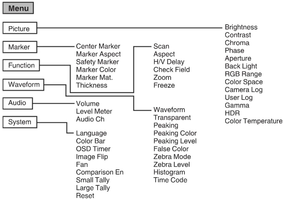
flowchart
graph TD
    A["Menu"] --> B["Picture"]
    A --> C["Marker"]
    A --> D["Function"]
    A --> E["Waveform"]
    A --> F["Audio"]
    A --> G["System"]
    B --> H["Brightness"]
    B --> I["Contrast"]
    B --> J["Chroma"]
    B --> K["Phase"]
    B --> L["Aperture"]
    B --> M["Back Light"]
    B --> N["RGB Range"]
    B --> O["Color Space"]
    B --> P["Camera Log"]
    B --> Q["User Log"]
    B --> R["Gamma"]
    B --> S["HDR"]
    B --> T["Color Temperature"]

    C --> U["Center Marker"]
    C --> V["Marker Aspect"]
    C --> W["Safety Marker"]
    C --> X["Marker Color"]
    C --> Y["Marker Mat. Thickness"]

    D --> Z["Scan Aspect"]
    D --> AA["H/V Delay"]
    D --> AB["Check Field"]
    D --> AC["Zoom Freeze"]

    E --> AD["Volume Level Meter"]
    E --> AE["Audio Ch"]

    F --> AF["Waveform Transparent"]
    F --> AG["Peaking Peaking Color"]
    F --> AH["Peaking Level False Color"]
    F --> AI["Zebra Mode Zebra Level Histogram Time Code"]

    G --> AJ["System"]
    AJ --> AK["Language Color Bar OSD Timer Image Flip Fan Comparison En Small Tally Large Tally Reset"]
List of Viewfinder Menus
Setting value with the ● mark is the factory default.
Picture
Settings related to picture quality
| Item Description Setting Value | ||
| Brightness For adjusting the black level. 0 to ●50 | to 100 | |
| Contrast For adjusting the contrast level of the bright areas in the image. | 0 to ●45 to 100 | |
| Chroma For adjusting the color density. 0 to ●50 to 100 | ||
| Phase For setting the color phase. 0 to ●50 to 100 | ||
| Aperture Corrects the frequency characteristics of luminance signals. | ●0 to 100 | |
| Back Light For adjusting the brightness of the backlight. | 0 to ●50 to 100 | |
| RGB Range (HDMI only) | For selecting the data format of the RGB input signal. | ●Limited, Full |
| Color Space For configuring the color gamut. ●Rec709, EBU, Native, SMPTE-C | ||
| Camera Log For selecting a camera log mode. • Optimally reproduces the different camera log signals. | ●Off, J-Log to Rec709, J-Log to 709HLG, J-Log to 709PQ, HLG75 to Rec709, HLG65 to Rec709, 2100HLG to 709HLG User LogJ-Log to Rec709:Converts J-Log to ITU REC709. Configuring Color Space to Rec709 and HDR to Off helps to optimize the display.J-Log to 709HLG:Converts J-Log to HDR HLG gamma and the color gamut to Rec709. Configuring Color Space to Rec709 and HDR to HLG helps to optimize the display.J-Log to 709PQ:Converts J-Log to 1000cd/m^2 PQ gamma and the color gamut to Rec709. Configuring Color Space to Rec709 and HDR to ST 2084 1000 helps to optimize the display.HLG75 to Rec709:Converts the HLG signals of ITU2100 to the Rec709 color space. This setting converts 75% HLG output to signals equivalent to a 100% reflectance subject. Configuring Color Space to Rec709 and HDR to Off helps to optimize the display.HLG65 to Rec709:Converts the HLG signals of ITU2100 to the Rec709 color space. This setting converts 65% HLG output to signals equivalent to a 100% reflectance subject. Configuring Color Space to Rec709 and HDR to Off helps to optimize the display.2100HLG to 709HLG:Converts ITU2100 HLG to HLG gamma and the color gamut to Rec709. Configuring Color Space to Rec709 and HDR to HLG helps to optimize the display. | |
| User Log For selecting a user log file. User' N' (N = 1 to 6)(P17 [ [User Log] ]) | ||
| Gamma For selecting a gamma correction value.(1.8: equivalent to γ1.8, 2.0: equivalent to γ2.0, 2.2: equivalent to γ2.2, 2.35: equivalent to γ2.35, 2.4: equivalent to γ2.4, 2.6: equivalent to γ2.6, 2.8: equivalent to γ2.8) | Off, 1.8, 2.0, ●2.2, 2.35, 2.4, 2.6, 2.8 | |
| HDR For selecting a preset HDR. ●Off, ST 2084 | 300, ST 2084 1000, ST 2084 10000, HLG | |
| Color Temperature | For selecting a color temperature. | 5500K, ●6500K, 9300K, UserSelecting User enables adjustment of the white balance. (Default value: 6500K)Gain/Offset points of Red, Green and Blue can be adjusted.Gain: 0 to ●128 to 255Offset: 0 to ●256 to 511 |
[User Log]
Follow the steps below to install the user log.
Data order is BGR (17x17x17).
① Create a user log file name in the [User'N'.cube] format and copy the user log file to a USB device. (Multiple user log files can be loaded at the same time.)
② When a USB device is connected, a [Load User'N' cube] display will appear on the screen together with a [No Yes] display.
- Turn the [VOL./MENU/SET] knob (button) to select [Yes] or [No], followed by pressing and holding down the [VOL./MENU/SET] knob (button) for 3 seconds or longer.
- After selecting [Yes] and loading has successfully completed, the LED of the [▲/F1] button starts flashing. Remove the USB device immediately when the LED starts flashing.
- If [No] is selected, the menu disappears. Remove the USB device immediately. If multiple user log files are stored in the USB device, select [Yes] or [No] for all of the files.
("N" corresponds to a numerical value between 1 and 6.)
Marker
Settings on the marker feature
| Item Description Setting Value | ||
| Center Marker | Displays or hides the marker that appears at the center of the video image. | ●Off, On |
| Marker Aspect | For selecting an aspect ratio for the marker. | ●Off, 16:9, 1.85:1, 2.35:1, 4:3, 3:2 |
| Safety Marker | For selecting a safety marker range. | ●Off, 95%, 93%, 90%, 88%, 85%, 80% |
| Marker Color For selecting a marker color. ●White, Black, Red, Green, Blue | ||
| Marker Mat. For configuring the masking density for the marker selected in Marker Aspect. | ●Off, 1 to 7 | |
| Thickness For selecting a marker width. 1 to ●2 to 7 | ||
Function
Settings related to video images
| Item Description Setting Value | |
| Scan For selecting a scan mode. ●Aspect, 1:1, Zoom | Aspect:Enables the [Aspect] item.1:1:Displays in the same resolution as the input signal (life size). The aspect ratio varies with the input signal.Zoom:Enables the [Zoom] item. When Zoom is selected, the [VOL./MENU/SET] knob (button) switches to the mode for adjusting the position.(P10 [Names of Parts]) |
| Aspect For selecting an aspect ratio when “Aspect” is selected in [Scan]. | Full, ●16:9, 1.85:1, 2.35:1, 4:3, 3:2 |
| H/V Delay (SDI, Camera) | For selecting a H/V delay mode. ●Off, H, V, H/V |
| Check Field Displays the RGB or luminance signal components. | ●Off, Red, Green, Blue, Mono |
| Zoom For adjusting the zoom scale when “Zoom” is selected in [Scan]. | x1.1, x1.3, x1.4, x1.7, ●x2, x2.5, x3.3, x5, x10 |
| Freeze Freezes images of an instant (On). | ●Off, On |
Waveform
Settings related to video signals
| Item Description Setting Value | ||
| Waveform For | selecting a display mode. ●Off, Multi, Y, YPbPr, RGB, RGB Full | |
| Transparent For | selecting a background opacity when [Waveform] is configured to Y, YPbPr or RGB. | ●Off, 25%, 50% |
| Peaking Turns | on/off the peaking feature. ●Off, On | |
| Peaking Color | For selecting a peaking color. | ●Red, Green, Blue, White, Black |
| Peaking Level | For adjusting the peaking level. | 0 to ●50 to 100 |
| False Color | Turns on/off the false color feature. | ●Off, On |
| Zebra Mode | Turns on/off the zebra feature. | ●Off, On |
| Zebra Level For | adjusting the luminance level of the zebra display when [Zebra Mode] is configured to “On”. Switches to a zebra display when the luminance level exceeds the preconfigured value. | 0 % to ●100 % |
| Histogram For | selecting a histogram mode. ●Y, | RGB, ColorY: Displays the luminance component.RGB: Overlaps the display of the three RGB colors.Color: Displays each of the RGB colors side by side without overlapping. |
| Time Code (SDI only) | For selecting a time code mode. ●Off, LTC, VITC | |
Audio
Settings on audio signals
| Item Description Setting Value | ||
| Volume For adjusting the volume. 0 to ●50 to 100 | ||
| Level Meter Displays or hides the level meter.• Ch1-Ch16 is forcibly displayed when [Waveform] is configured to “Multi”.• [Level Meter] only supports 1ch and 2ch during HDMI input. (The display will either be Ch1-Ch4 or Ch1-Ch16.) | ●Off, Ch1-Ch4, Ch1-Ch16 | |
| Audio Ch (SDI, Camera) | For selecting an audio channel mode. | ●Ch1&Ch2, Ch3&Ch4, Ch1+Ch3&Ch2+Ch4, Ch5&Ch6, Ch7&Ch8, Ch9&Ch10, Ch11&Ch12, Ch13&Ch14, Ch15&Ch16 |
System
General settings
| Item Description Setting Value | ||
| Language For | configuring the display language of the menus. | ●English, 中文, Deutsch, Français, Italiano, Español, Русский |
| Color Bar | For configuring the color bar to on or off. | ●Off, 100%, 75% |
| OSD Timer For | selecting an OSD display duration. | ●10s, 20s, 30s |
| Image Flip For | selecting an image inversion feature. | ●Off, H, V, H/V |
| Fan For configuring the fan strength. ●Auto, On, Off | ||
| Comparison En | Displays the right half of the image in the selected settings.Configure this item to make a comparison between the original image (left) and the configured image (right). | ●Off, Gamma&HDR, Color Space, Camera Log |
| Small Tally For | selecting a brightness level for the small tally lamp. | ●Off, Low, High |
| Large Tally For | selecting a brightness level for the large tally lamp. | ●Off, Low, High |
| Reset Restores | all the settings on this unit to the factory settings. (Reset) | Off, On |
Troubleshooting
| Troubleshooting Check | |
| Power does not turn on Ensure | the VF cable and power cable are plugged in securely. Turn on the power of the camera. Check the position of the power switch at the back of this unit. |
| No video image Ensure that the VF cable is plugged in securely. Turn on the power of the camera and configure correctly. | |
Specifications
General
| Item Description | |
| Device to be connected GY-HC900 | |
| Power DC 12 V (10.5 V to 17 V) | |
| Rated current 1.4 A (DC 12 V) | |
| Allowable operating temperature 0 °C | to 40 °C (32 °F to 104 °F) |
| Allowable operating humidity 30 %RH | to 80 %RH |
| Mass 1.0 kg |
LCD Specifications
| Item Description | |
| Screen size 7.0 inch | |
| Aspect ratio 16:10 | |
| Resolution WUXGA (1920×1200) 8 bit | |
| Effective screen dimensions 15.1 cm (width), 9.8 cm (height), 18.0 cm (diagonal) | |
| Viewing angle (TYP.) Horizontal: 160° | Vertical: 160° |
| Luminance | 450 cd/m2 |
| Contrast ratio 1100:1 | |
Input/Output Terminal
| Item | Terminal | Description |
| Video | HDMI HDMI signal input (HDCP-compatible, linear PCM): HDMI connector x 1 | |
| SDI IN | Digital signal input (3G/HD/SD SDI, supports embedded audio): auto detection, BNC connector x 1 | |
| SDI OUT | Digital signal output (3G/HD/SD SDI, supports embedded audio): BNC connector x 1 | |
| VF CABLE | 26-pin connector (terminal used exclusively for camera: video, audio, power, control) x 1 | |
| Audio | PHONE | 3.5 mm stereo mini jack x 1 |
| Data | USB | USB2.0 type A x 1 |
| Power | DC IN | XLR 4-pin DC 12 V (10.5 V to 17 V) x 1 |
Accessories
| Accessories Quantity | |
| INSTRUCTIONS 1 | |
| Warranty Card (for USA)*The Warranty Card is included in the INSTRUCTIONS. | 1 |
| 使用说明书 (for CHINA) 1 | |
| 保修卡 (for CHINA)*The 保修卡 is included in the 使用说明书. | 1 |
| VF cable (0.8 m) 1 | |
| Number plate 3 | |
| Protective cover 1 | |
| Protective cover mounting screws (M2) 4 | |
| Shoe mount 1 |
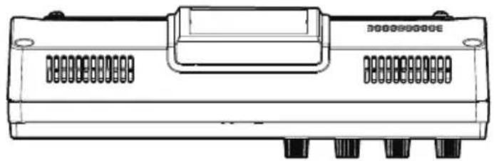
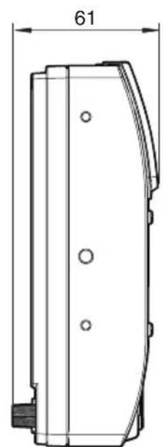
Dimensional Outline Drawing (Unit: mm)
natural_image
Technical line drawing of a mechanical component with ports and mounting holes (no text or symbols)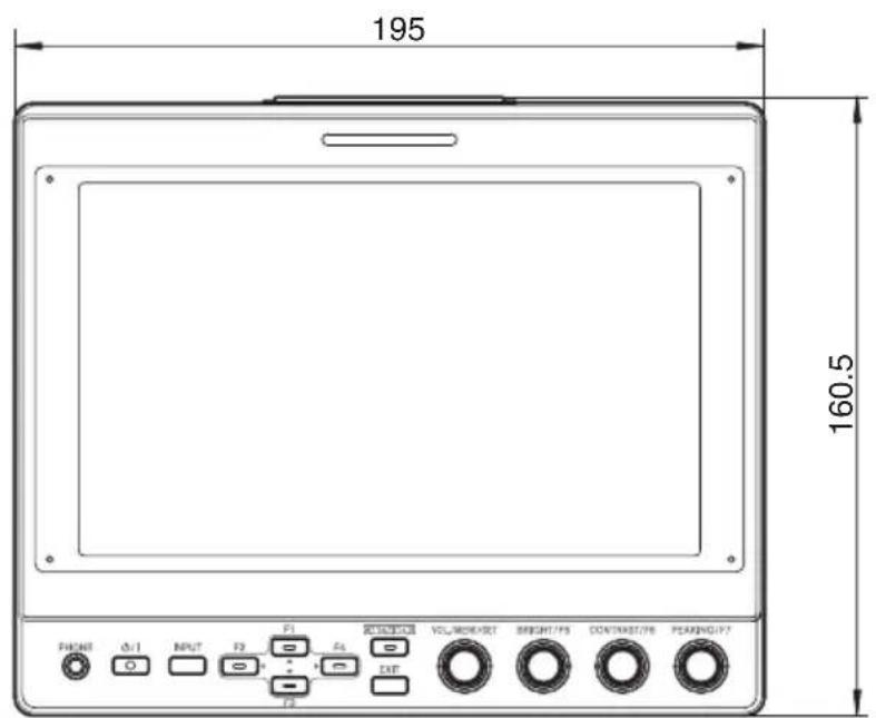
natural_image
Technical line drawing of a mechanical component with dimension标注 (no text or symbols)* The specifications and appearance of this product are subject to changes for further improvement without prior notice.
Available Signal Formats
VF-HP900G Available Signal Format
| Signal Format | STATUS Display(3 Input Signal) | INPUT | |||
| SDI (SD/HD/3G) HDMI Camera | |||||
| 1080/60i 1080i60Hz | √ | √ | - | ||
| 1080/59.94i 1080i59.94Hz | √ | √ | √ | ||
| 1080/50i 1080i50Hz | √ | √ | √ | ||
| 1080/60p 1080p60Hz | √ | √ | - | ||
| 1080/59.94p 1080p59.94Hz | √ | √ | - | ||
| 1080/50p 1080p50Hz | √ | √ | - | ||
| 1080/30p 1080p30Hz | √ | √ | - | ||
| 1080/29.97p 1080p29.97Hz | √ | √ | - | ||
| 1080/25p 1080p25Hz | √ | √ | - | ||
| 1080/24p 1080p24Hz | √ | √ | - | ||
| 1080/23.97p 1080p23.98Hz | √ | √ | - | ||
| 1080/30psf 1080sf30Hz | √ | - | - | ||
| 1080/29.97psf 1080sf29.97Hz | √ | - | - | ||
| 1080/25psf 1080sf25Hz | √ | - | - | ||
| 1080/24psf 1080sf24Hz | √ | - | - | ||
| 1080/23.97psf 1080sf23.98Hz | √ | - | - | ||
| 720/60p 720p60Hz | √ | √ | - | ||
| 720/59.94p 720p59.94Hz | √ | √ | - | ||
| 720/50p 720p50Hz | √ | √ | - | ||
| 720/30p 720p30Hz | √ | √ | - | ||
| 720/29.97p 720p29.98Hz | √ | √ | - | ||
| 720/25p 720p25Hz | √ | √ | - | ||
| 720/24p 720p24Hz | √ | √ | - | ||
| 720/23.97p 720p23.97Hz | √ | √ | - | ||
| 480/59.94i 480i59.94Hz | √ | - | - | ||
| 576/50i 576i50Hz | √ | - | - | ||
| 640x480/60p 640x480 60Hz - | √ | - | |||
| 720(x2)x480/60i | 480i60Hz | - | √ | - | |
| 720(x2)x576/50i | 576i50Hz | - | √ | - | |
| 480/60p 480p60Hz | - | √ | - | ||
| 480/59.94p 480p59.94Hz | - | √ | - | ||
| 576/50p 576p50Hz | - | √ | - | ||
| 640x480/60Hz | 640x480 59.94Hz | - | √ | - | |
| 800x600/60Hz | 800x600 60Hz - | √ | - | ||
| 1024x768/60Hz | 1024x768 60Hz | - | √ | - | |
| 1280x1024/60Hz 1280x1024 60Hz | - | √ | - | ||
| 1920x1200/60HzRB | 1920x1200 59.94Hz | - | √ | - | |
STATUS Display
The following information is displayed at the bottom of the viewfinder menu screen.
① Input mode (SDI/HDMI/Camera)
② 3G-SDI mapping information (LevelA/LevelB) only in 3G-SDI mode
③ Input signal format (1080p59.94Hz, ...)
Memo :
Information displayed in STATUS Display will not appear on the screen even after switching the input or signal. To view the information, press the [VOL./MENU/SET] knob (button).
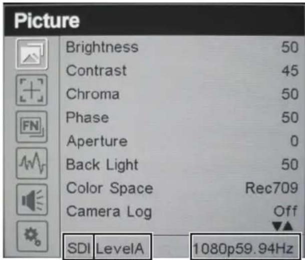
① ② ③
Information on Disposal of Old Electrical and Electronic Equipment and Batteries (applicable for countries that have adopted separate waste collection systems)

Products and batteries with the symbol (crossed-out wheeled bin) cannot be disposed as household waste. Old electrical and electronic equipment and batteries should be recycled at a facility capable of handling these items and their waste by products.

Contact your local authority for details in locating a recycle facility nearest to you.
Proper recycling and waste disposal will help conserve resources whilst preventing detrimental effects on our health and the environment.
Notice: The sign "Pb" below the symbol for batteries indicates that this battery contains lead.
WHAT IS NOT COVERED:
This limited warranty provided by JVC does not cover:
- Products which have been subject to abuse, accident, alteration, modification, tampering, negligence, misuse, faulty installation, lack of reasonable care, or if repaired or serviced by anyone other than a service facility authorized by JVC to render such service, or if affixed to any attachment not provided with the products, or if the model or serial number has been altered, tampered with, defaced or removed;
- Initial installation, installation and removal from cabinets or mounting systems.
- Operational adjustments covered in the Owner's Manual, normal and recommended maintenance, and replacement of consumable parts, video and audio head cleaning;
- Damage that occurs in shipment, due to act of God, and cosmetic damage;
- Signal reception problems and failures due to line power surge;
- Video head, CCD Image Sensors, DILA devices are covered for 90 days from the date of purchase:
- Accessories
- Batteries (except that Rechargeable Batteries are covered for 90 days from the date of purchase).
There are no express warranties except as listed above.
THE DURATION OF ANY IMPLIED WARRANTIES, INCLUDING THE IMPLIED WARRANTY OF MERCHANTABILITY, IS LIMITED TO THE DURATION OF THE EXPRESS WARRANTY HEREIN.
JVC SHALL NOT BE LIABLE FOR ANY LOSS OF USE OF THE PRODUCT, INCONVENIENCE OR ANY OTHER DAMAGES, WHETHER DIRECT, INCIDENTAL OR CONSEQUENTIAL (INCLUDING, WITHOUT LIMITATION, DAMAGE TO TAPES, RECORDS OR DISCS) RESULTING FROM THE USE OF THIS PRODUCT, OR ARISING OUT OF ANY BREACH OF THIS WARRANTY. ALL EXPRESS AND IMPLIED WARRANTIES, INCLUDING THE WARRANTIES OF MERCHANTABILITY AND FITNESS FOR PARTICULAR PURPOSE, ARE LIMITED TO THE WARRANTY PERIOD SET FORTH ABOVE.
Some states do not allow the exclusion of incidental or consequential damages or limitations on how long an implied warranty lasts, so these limitations or exclusions may not apply to you. This warranty gives you specific legal rights and you may also have other rights which vary from state to state.
REFURBISHED PRODUCTS CARRY A SEPARATE WARRANTY, THIS WARRANTY DOES NOT APPLY. FOR DETAIL OF REFURBISHED PRODUCT WARRANTY, PLEASE REFER TO THE REFURBISHED PRODUCT WARRANTY INFORMATION PACKAGED WITH EACH REFURBISHED PRODUCT.
RETAIN THIS PART OF YOUR WARRANTY
FIRST-CLASS POSTAGE REQUIRED POST OFFICE WILL NOT DELIVER WITHOUT PROPER POSTRAGE
JVC
JVCKENWOOD USA Corporation
PO Box 22745
2201 E. Dominguez St, Long Beach, CA 90810-5745
JVC
LIMITED WARRANTY
PRO. PRODUCTS 2-1 CI
JVCKENWOOD USA Corporation (JVC) warrants this product and all parts thereof, except as set forth below ONLY TO THE ORIGINAL END-USER PURCHASER to be FREE FROM DEFECTIVE MATERIALS AND WORKMANSHIP from the date of the original purchase for the period shown below. ("The Warranty Period")
| Model | Serial No. | Parts | Labor |
| VF-HP900G | 2YR | 1YR |
THIS LIMITED WARRANTY IS VALID ONLY IN THE FIFTY (50) UNITED STATES, THE DISTRICT OF COLUMBIA AND IN THE COMMONWEALTH OF PUERTO RICO.
WHAT WE WILL DO:
If this product is found to be defective within the warranty period, JVC will repair or replace defective parts with new or rebuilt equivalents at no charge to the original owner. Such repair and replacement services shall be rendered by JVC during normal business hours at JVC authorized service centers. Parts used for replacement are warranted only for the remainder of the Warranty Period.
WHAT YOU MUST DO FOR WARRANTY SERVICE:
Box the product carefully, preferably in the original carton and ship to the nearest JVC authorized service center. It is recommended that you insure the product against loss or damage. To obtain the address of the nearest authorized service center, please call (800) 582-5825. Service locations can also be obtained from our website at http://www.us.jvckenwood.com.
Please be sure to include a copy of your bill of sale to substantiate warranty (if applicable) and a note detailing the problem. If you have any questions concerning your JVC Product, please contact our Customer Relations Department at 800-582-5825.
SEE OTHER SIDE
JVCKENWOOD USA Corporation
PO Box 22745, 2201 E. Dominguez St,
Long Beach, CA 90810-5745
PRODUCT SAFETY REGISTRATION CARD
To help us better serve you, we request you to return this "PRODUCT SAFETY REGISTRATION CARD". The information will enable us to contact you quickly if it is ever necessary to correct a safety related condition in this product.
Thank you for helping us to service you better.
Please fill in the requested information and mail or you can register your product online at: http://www.jvc.com/pro
THIS IS NOT A WARRANTY REGISTRATION CARD. PLEASE RETAIN YOUR BILL OF SALE FOR PROOF OF WARRANTY.
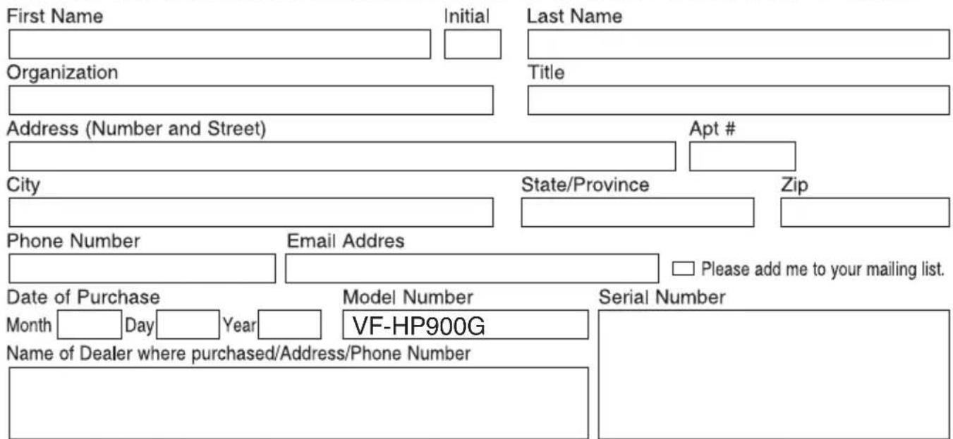
This form is for Product Registration purpose only. Failure to return this form does not diminish your rights during the warranty period.


- About INSTRUCTIONS
- Please read the following before getting started:
- For Customer Use:
- Safety Precautions
- FOR USA
- Important Safety Instructions
- POUR LES ÉTATS-UNIS
- FOR USA AND CANADA
- CAUTION
- CAUTION:
- POUR CANADA
- ATTENTION
- ATTENTION:
- WARNING: TO PREVENT FIRE OR SHOCK HAZARD, DO NOT EXPOSE THIS UNIT TO RAIN OR MOISTURE.
- NOTES:
- WARNING
- Dear Customer
- Preparations
- Menu
- Others
- Symbols used
- Content of this manual
- Precautions for Proper Use
- Location of Storage and Use
- Handling the Product
- Moving the Product
- Maintenance
- Energy Conservation
- LCD Screen
- Bright/Dark Spots
- Maintaining the LCD Screen
- Disposal
- Names of Parts
- Front
- Connecting the VF Cable
- Attaching the Protective Cover
- Attaching the Number Plate
- Attaching the Shoe Mount
- Operating the Viewfinder Menus
- Operating the Camera Menus
- Configuring Shortcuts (Function Button)
- Configuration Method
- Shortcut Menus for Auxiliary Features (F1 to F4)
- Memo :
- Shortcut Menus for Picture Quality and Volume (F5 to F7)
- Viewfinder Menu Flow Chart
- List of Viewfinder Menus
- Picture
- [User Log]
- Marker
- Function
- Waveform
- Available Signal Formats
- STATUS Display
- Information on Disposal of Old Electrical and Electronic Equipment and Batteries (applicable for countries that have adopted separate waste collection systems)
- WHAT IS NOT COVERED:
- JVC
- LIMITED WARRANTY
- WHAT WE WILL DO:
- WHAT YOU MUST DO FOR WARRANTY SERVICE:
- PRODUCT SAFETY REGISTRATION CARD
Brand : JVC
Model : VF-HP900
Category : Headphones