OEM-2 - Car kit PAC - Free user manual and instructions
Find the device manual for free OEM-2 PAC in PDF.


| Product Type | Universal Sound System Interface and Controller |
| Brand | PAC |
| Model | OEM-2 |
| Category | Car Kit |
| Compatible Systems | Premium factory radios, standard factory speaker systems, factory amplified systems (Bose, JBL, etc.), floating ground radios (early Fords) |
| Channel Configuration | 4 channels (LF, RF, LR, RR) |
| Input Types | High power speaker level (up to 20W+), low power speaker level, low level (pre-amp) for amplified systems |
| Output Types | Speaker level (high/low power), low level RCA, common ground speaker output, remote turn-on (12V, 2A max) |
| Remote Turn-On Trigger | 0.8V minimum input, 12V 2A output, 1 second delay |
| Power Supply | 12V DC (yellow constant, red switched, black ground) |
| Level Control | Adjustable with small screwdriver (per channel pair) |
| Dimensions (approx.) | 4 x 2 x 1 inches (10 x 5 x 2.5 cm) |
| Weight (approx.) | 0.5 lbs (225 g) |
| Wiring Harness | Input and output wires color-coded (see manual for full diagram) |
| Illumination/Dimming | Orange wire for dash illumination dimming |
| Power Antenna Output | Blue wire, 12V when radio on |
| Operating Temperature | 32°F to 122°F (0°C to 50°C) |
| Maintenance | Wipe with dry cloth; avoid moisture and extreme temperatures |
| Installation | Requires basic wiring knowledge; connect per vehicle-specific configuration |
| Warranty | 1 year limited manufacturer warranty |
Frequently Asked Questions - OEM-2 PAC
User questions about OEM-2 PAC
0 question about this device. Answer the ones you know or ask your own.
Ask a new question about this device
Download the instructions for your Car kit in PDF format for free! Find your manual OEM-2 - PAC and take your electronic device back in hand. On this page are published all the documents necessary for the use of your device. OEM-2 by PAC.
USER MANUAL OEM-2 PAC
Universal sound system interface and controller
The OEM-2 may be used in any one of four possible configurations and system types.
1) Replacing a premium factory radio with an aftermarket stereo and use the factory amplifier and speakers.
2) Four channel line out converter for adding amplifiers to a standard factory speaker system.
3) Adding aftermarket amplifiers to a factory premium amplified system (Bose, JBL, etc.).
4) Installing a radio with floating ground speaker outputs to a common grounded speaker system like the early Fords.
The OEM-2 also includes a remote turn-on for amplifiers or a power antenna, providing 2 amps at 12 volts when 0.8 volts or greater is applied to the input side. This is useful for low voltage triggers like those used in Fords or for automatic triggering when audio is present. The output "turn on" is delayed 1 second to prevent turn on pops.
| Input wiring colors | Output wiring colors | |||
| White ^1 | LF (+) speaker (high power) | White ^6 | LF (+) low level output | |
| White/red ^2 | LF (+) speaker (low power) White/red | LF (+) common gnd. speaker output | ||
| White/black ^3 | LF (−) common | White/black ^7 | LF (−) common | |
| Gray ^1 | RF (+) speaker (high power) | Gray ^8 | RF (+) low level output | |
| Gray/red ^2 | RF (+) speaker (low power) Gray/red | RF (+) common gnd. speaker output | ||
| Gray/black ^3 | RF (−) common | Gray/black ^7 | RF (−) common | |
| Green ^1 | LR (+) speaker (high power) | Green ^8 | LR (+) low level output | |
| Green/red ^2 | LR (+) speaker (low power) Green/red | LR (+) common gnd. speaker output | ||
| Green/black ^3 | LR (−) common | Green/black ^7 | LR (−) common | |
| Violet ^1 | RR (+) speaker (high power) | Violet ^6 | RR (+) low level output | |
| Violet/red ^2 | RR (+) speaker (low power) Violet/red | RR (+) common gnd. speaker output | ||
| Violet/black ^3 | RR (−) common | Violet/black ^7 | RR (−) common | |
| Yellow ^4 | Constant battery Yellow Constant battery | |||
| Red ^4 | Switched power Red Switched power | |||
| Black ^4 | Gnd. neg. power Black Gnd. neg. power | |||
| Blue ^4 | Power antenna turn on | Blue | Power antenna turn on | |
| Blue/white ^5 | Amplifier remote turn on 0.8 v min. | Blue/white | Amplifier remote turn on 2 amps max. | |
| Orange ^4 | Illumination dimming | Orange | Illumination dimming | |
^1 Connect these wires to an aftermarket radio (+) high power speaker output (typically 20 watts x 4 and higher).
^2 Connect these wires to an aftermarket radio (+) low power speaker output. (All stereos up to 20 watts x 4 or when wiring for #4)
^3 If the radio is high power (floating ground), connect these wires separately to each of the radio's speaker (-) wire (do not connect (-) speaker wires together). If the radio has a common ground speaker outputs, connect these wires together along with the radio's speaker ground.
^4 These wires go directly through to the outputs for convenience of wiring. The red and black wires supply power to the internal low voltage trigger.
^5 This wire needs only a minimum of 0.8 volts to supply 12 volts on the blue/white wire on the output side of the OEM-2.
^6 For convenience, the positive leads of the RCA are connected internally to these wires.
^7 For convenience, the grounds of the RCA are connected internally to these wires. Not used with common grounded speakers.
Note: Some Chrysler/Dodge vehicles with a Infinity premium sound system do not need any interface. If the speakers fade and balance correctly with this interface installed, but you have very little volume, then you do not need this interface.
1) Replace the factory premium radio with an after market radio/deck and retain the use of the factory amplifiers and speakers
Referring to the wire color chart above, connect the speaker outputs of the new radio to the OEM-2, using the positive, solid color, and the negative black-striped wires for all four channels. On the output side of the OEM-2 connect the solid color wires (+) and the black-striped wires (-) to the factory harness leading to the factory amplifiers. If there are common audio return wires (-) used in the vehicle for either the front and rear channels then connect the negative outputs of the OEM-2 to them. If there is only one audio return wire for all four channels connect all the black-striped wires to it. Connecting the constant power (yellow), switched power (red), ground (black), antenna trigger (blue), illumination (orange), and amplifier turn on (blue/white) through the OEM-2 simplifies wiring to the vehicle. The output level controls can be adjusted with a small screwdriver.

flowchart
graph LR
    A["Aftermarket stereo"] -->|102.7 FM| B["PAC OEM-2"]
    B -->|wht & wht/blk| C["Output"]
    B -->|gray & gray/blk| D["Output"]
    B -->|gm & grav/blk| E["Output"]
    B -->|vic & viq/blk| F["Output"]
    B -->|plug removed from factory stereo| G["Factory Amplifier"]
    G --> H["RF"]
    G --> I["RR"]
    G --> J["LF"]
    G --> K["LR"]
    B -->|blue/wht amplifier remote turn on| G
    style A fill:#f9f,stroke:#333
    style G fill:#ccf,stroke:#333
2) Adding an aftermarket amplifier to a standard factory radio that does not have factory amplifiers
The factory radio speaker outputs are connected to the OEM-2 inputs and the new amplifier is connected to the output side of the OEM-2, using the four RCA jacks and extension cables. Referring to the wire color chart, connect the factory radio speaker (+) outputs to the solid color wires and the (-) outputs to the black-striped wires. Example, LF speaker outputs of the factory radio connect to the white wire (+) and white/black (-). Continue for the remaining channels. The OEM-2 provides an amplifier turn on signal. To use, connect the blue/white wire on the OEM-2 input side to one of the positive speaker wires or to any source that provides 5 volts DC or greater. The blue/white wire on the output side will provide 12 volts to turn on the new amplifier. Connect the red (+) and black (-) wires on the input side to switched vehicle power and ground. Adjust the output level controls as needed using a small screwdriver.

flowchart
graph TD
    A["Factory stereo"] --> B["102.7 FM"]
    B --> C["PAC OEM-2"]
    C --> D["Output"]
    D --> E["New Amplifier"]
    E --> F["New subwoofers"]
    C --> G["RL"]
    C --> H["RR"]
    C --> I["RF"]
    C --> J["green &gm/blk"]
    C --> K["violet &vlo/blk"]
    C --> L["gray & gray/blk"]
    C --> M["white &wht/blk"]
    C --> N["blu/wht"]
    style A fill:#f9f,stroke:#333
    style E fill:#ccf,stroke:#333
    style F fill:#cfc,stroke:#333
    style G fill:#fcc,stroke:#333
    style H fill:#fcc,stroke:#333
    style I fill:#fcc,stroke:#333
    style J fill:#fcc,stroke:#333
    style K fill:#fcc,stroke:#333
    style L fill:#fcc,stroke:#333
    style M fill:#fcc,stroke:#333
    style N fill:#fcc,stroke:#333
    style_O["Connect blue/wht wire to any speaker wire output of factory radio (+ or -) for remote turn on for new amplifier."] --> P["Output"]
    P --> Q["RCA out to new amplifier"]
3) Adding after market amplifiers to a factory premium amplified system (Bose, JBL, etc.)
Referring to the wire color chart above, connect the audio output leads of the factory stereo to the input of the OEM-2, using the red striped wires as the positive input and black-striped as negative. Most premium systems use a low-level signal from the stereo to the factory amplifiers, therefore use the low level input of the OEM-2. Some factory-amplified systems use common audio returns and grounded shields like for instance, GM/Delco Bose vehicles. Do not cut the shield wire or attempt to use it as an audio signal wire. Determine if your system has two common audio return wires, one for the front channels and a second for the rear channels. If so, connect the negative input wires (black-stripe) for the front channels of the OEM-2 to the common audio return wire in the vehicle for the front channels. Do the same for the rear channels. If the vehicle has only one audio return wire for all channels connect all of the black stripped wires to it. The output level controls can be adjusted with a small screwdriver. Connect the red (+) and black (-) wires on the input side to switched vehicle power and ground.
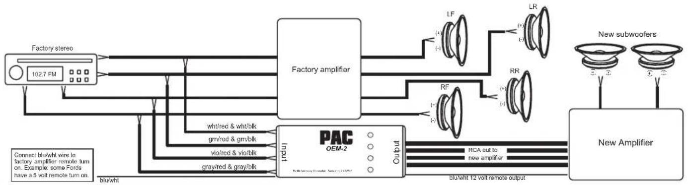
flowchart
graph TD
    A["Factory stereo"] --> B["Factory amplifier"]
    C["New Subwoofer"] --> D["PAC OEM-2"]
    B --> E["Output"]
    D --> F["Output"]
    B --> G["RL"]
    B --> H["RR"]
    B --> I["LF"]
    B --> J["RF"]
    B --> K["wht/Red & wht/blk"]
    B --> L["gm/Red & gm/blk"]
    B --> M["vio/Red & vio/blk"]
    B --> N(gray/Red & gray/blk]
    D --> O["New Amplifier"]
    D --> P["Blue/Wht 12 volt remote output"]
    style A fill:#f9f,stroke:#333
    style C fill:#f9f,stroke:#333
    style D fill:#ccf,stroke:#333
    style B fill:#cff,stroke:#333
    style D fill:#ffc,stroke:#333
    style B fill:#cfc,stroke:#333
    style D fill:#fcc,stroke:#333
    style B fill:#ffc,stroke:#333
    style D fill:#fcc,stroke:#333
    style B fill:#ffc,stroke:#333
    style D fill:#fcc,stroke:#333
4) Installing a radio with floating ground speaker outputs to a common grounded speaker system like the early Fords.
Referring to the wire color chart, connect the new stereo positive speaker outputs to the red striped wire on the input side of the OEM-2. Connect the negative speaker outputs to the black-striped wires of the OEM-2. On the output side of the OEM-2 connect the red-striped wires to the vehicle positive speaker wiring. The black striped wires on the output are not used. The negative side of each speaker is either common to each other on one wire or two in the factory plug or already grounded to the chassis. However it may be, make sure that they are grounded to the vehicle chassis. The output level control on the OEM-2 will not function in this configuration.

flowchart
graph LR
    A["Aftermarket stereo"] --> B["102.7 FM"]
    B --> C["wht/red &wht/blk"]
    B --> D(gray/red & gray/blk]
    B --> E["grn/red &gm/blk"]
    B --> F["vio/red &vio/blk"]
    C --> G["PAC OEM-2"]
    D --> G
    E --> G
    F --> G
    G --> H["Output"]
    H --> I["wht/red (+)"]
    H --> J["(-)"]
    H --> K["LF"]
    H --> L["grn/red (+)"]
    H --> M["LR"]
    H --> N["RR"]
    H --> O["gry/red (+)"]
    H --> P["vio/red (+)"]
    H --> Q["(-)"]


- Universal sound system interface and controller
- 1) Replace the factory premium radio with an after market radio/deck and retain the use of the factory amplifiers and speakers
- 2) Adding an aftermarket amplifier to a standard factory radio that does not have factory amplifiers
- 3) Adding after market amplifiers to a factory premium amplified system (Bose, JBL, etc.)
- 4) Installing a radio with floating ground speaker outputs to a common grounded speaker system like the early Fords.
Brand : PAC
Model : OEM-2
Category : Car kit