
RP5-GM32 - Car kit PAC - Free user manual and instructions
Find the device manual for free RP5-GM32 PAC in PDF.


| Product Type | Car Stereo Installation Kit |
| Brand | PAC |
| Model | RP5-GM32 |
| Compatibility | General Motors vehicles (1998-2008) |
| Functions | Retains factory OnStar, chimes, and audio features; integrates aftermarket radio |
| Power Supply | 12V DC from vehicle battery |
| Dimensions | 6 x 4 x 2 inches (approx.) |
| Weight | 0.5 lbs (approx.) |
| Material | Plastic and metal |
| Color | Black |
| Includes | Wiring harness, antenna adapter, mounting brackets |
| Installation Tools | Basic hand tools (screwdrivers, trim removal tools) |
| Maintenance | Wipe with a dry, lint-free cloth |
| Safety | Disconnect vehicle battery before installation |
| Spare Parts | No spare parts required; unit is non-serviceable |
| Reparability | Not user-serviceable; replace entire unit if defective |
| Certifications | CE, RoHS |
Frequently Asked Questions - RP5-GM32 PAC
User questions about RP5-GM32 PAC
0 question about this device. Answer the ones you know or ask your own.
Ask a new question about this device
Download the instructions for your Car kit in PDF format for free! Find your manual RP5-GM32 - PAC and take your electronic device back in hand. On this page are published all the documents necessary for the use of your device. RP5-GM32 by PAC.
USER MANUAL RP5-GM32 PAC
Introduction and Features
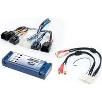
The RP5-GM32 interface allows the replacement of a factory radio in select General Motors vehicles with 29 Bit Data-Bus. Using this interface will retain factory features such as Warning Chimes, Bose Amplifier, Steering Wheel Controls (SWC), Rear Seat Entertainment (RSE), and Rear Seat Controls (RSC) when the original radio is removed. The RP5-GM32 provides data bus driven outputs such as retained accessory power (RAP), vehicle speed signal (VSS), illumination, reverse trigger and parking brake.
Important Notes
- Aftermarket radio must have an auxiliary input in order to retain RSE audio with additional harness sold separately. Part# (GMRVD2).
- Aftermarket radios with a 2-wire resistive based SWC circuit will not have default button assignments programmed. Please refer to the owners manual of the radio you are installing to find out the proper SWC programming procedure.
- If the vehicle chimes when the radio is removed, the CMX is not necessary. In order to get the best possible sound out of the CMX, please mount it in a place free and clear of any obstructions, preferably as close as possible to the bottom of the dash pointing down toward the floor of the vehicle.
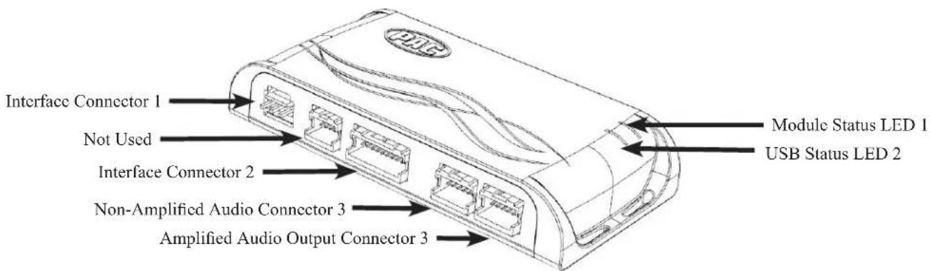
Module Layout

Installation Steps

Set DIP switches that correspond with your radio to the ON position. Set all other DIP switches to the OFF position.

| Alpine | JVC | Kenwood / Lightning Audio | Stinger | Clarion / Nakamichi | All Other Brands | Pioneer | Sony | Fusion |
| 1 | 2 | 1 & 2 | 3 | 3 | 1, 2, & 3 | 1, 2, & 3 | 4 | 1 & 4 |
If your brand is not listed above, please use "ALL OTHER BRANDS."
- Set the Radio Select DIP switches according to the radio you are installing.
- Wire your aftermarket radio to the RP5-GM32's harness according to the wiring connections chart below.
- The Brown mute loop in Interface Connector 4 (if not cut) will turn the RP5's accessory output off when any OnStar function is active. If the aftermarket radio has a mute input, cut this loop and connect the Brown wire in pin 23 to it. This pin is located in the top row next to the solid blue wire. (The top of the connector has the locking tab on it).
- Plug Interface Connectors 1 and 2 into the appropriate ports on the RP5-GM32 interface (using the diagram on Page 1 or the label on the bottom of the interface to identify the connector ports).
- The Connector 3 connection will be dependent upon whether or not the vehicle has a factory amplified system. Plug this connector into one of the two ports on the RP5-GM32 (using the diagram on Page 1 or the label on the bottom of the interface to identify the port appropriate for the installation).
- If the aftermarket radio is equipped with an auxiliary input and you wish to retain the factory RSE audio, plug the RCA connectors from the Vehicle Connector 2 into the radios auxiliary input.
- Remove the factory radio and plug in the RP5-GM32's Vehicle Connector 1 and Vehicle Connector 2 into the factory vehicle harness.
- If you wish to reassign functions to the SWC, follow the Optional Steering Wheel Control Programming on Page 4.
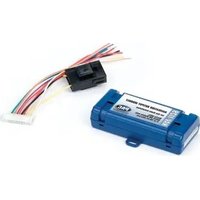
- Plug the 2-Pin connector into the CMX Chime Module (If the vehicle chimes when the radio is removed, the CMX is not necessary). PLEASE NOTE: In order to get the best possible sound out of the CMX, please mount it in a place free and clear of any obstructions, preferably as close as possible to the bottom of the dash pointing down toward the floor of the vehicle.

Interface Connector 1 (3-pin)

Interface Connector 2 (20-pin)

Interface Connector 3 (12-pin)

Interface Connector 4 (24-pin)

Vehicle Connector 1 (44-pin)

Vehicle Connector 2 (20-pin)
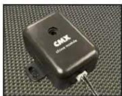
CMX Chime Module
Wiring Connections
| Yellow 12v+ | |
| Red | Accessory Output(10 amp) |
| Black Ground | |
| Brown Loop | Mute Output |
| Blue | Not Used |
| Blue / White | Remote On Input |
| Orange | Not Used |
| Orange / White | Illumination Output |
| Purple / White | Reverse Output (+) |
| Light Green | Parking Brake Output (-) |
| Pink | Vehicle Speed Signal(VSS) Output |
| Blue / Yellow | SWC Output / Key 1 |
| Brown | SWC Output / Key 2 |
| 3.5 mm Jack | SWC Output |
| Purple | Rear R + input |
| Purple / Black | Rear R - input |
| Green | Rear L + input |
| Green / Black | Rear L - input |
| Gray | Front R + input |
| Gray / Black | Front R - input |
| White | Front L + input |
| White / Black | Front L - input |
Programming Button and Adjustment Dial Functions
You can press and hold the programming button on the side of the interface to access different programming modes. Once the LED is lit to the mode you desire (see below for modes), immediately release the programming button to access that mode.
PLEASE NOTE:
- This process must be done with the interface in the vehicle and the key in the ignition position.
A. LED 1 flash green: SWC re-assignment. This allows you to re-assign the SWC functions to the buttons of your choice. Please see the Optional Steering Wheel Control Programming instructions on Page 4 for more details.
B. LED 1 flash red: Master reset. This does a master reset of the interface and restores the following settings to factory defaults:
- SWC Mapping
- SWC Calibration
Default Steering Wheel Control Programming
Default SWC Button Assignments
| Alpine JVC Kenwood Clarion Pioneer Sony Fusion | |||||||
| Volume + | Volume + Volume - | Volume + Volume - | Volume + Volume - | Volume + Volume - | + | ||
| Volume - | Volume - Volume - | Volume - Volume - | Volume - Volume - | Volume - Volume - | |||
| Source | Source | Source | Source | Source | Source | Source | Source |
| Track + | Track + | Track + | Track + | Search + | Track + | Track + | Track + |
| Track - | Track - | Track - | Track - | Search - | Track - | Track - | Track - |
| Voice | Mute | Mute | Mute | Mute | Mute | Mute | Mute |
| Play/Pause | Preset + | Preset/Disc - | Disc/FM+ | Band | Preset + | Preset + | Audio |
Optional Steering Wheel Control Programming
Factory Mode
- The SWC Mute / Voice buttons are programmed to control OnStar. They cannot be programmed for short press / long press dual command functionality and are blocked from doing so.
Aftermarket Mode
- OnStar control through the SWC Mute button is disabled. This will free up the Mute button to send mute radio command and a second function.
Optional Steering Wheel Control Programming (cont.)
Use the function chart on the next page as a guide to program the functions in the proper order for your new radio
- Turn the key to the ignition position.
- Press and release the programming button on the side of the interface the number of times that corresponds with either factory or aftermarket mode. One press will set factory mode and two presses will set aftermarket mode. The LED will blink each time the button is pressed.
- Once you have chosen either factory or aftermarket mode, after 2.5 seconds the LED will come on solid. At this point you have two options:
A. To restore the SWC to factory default settings: Simply wait 7 seconds and the LED will blink 3 times indicating the interface has timed out. The default settings are now restored and no further action is required.
B. To program custom SWC assignments: Proceed to step 4
- With the LED on, press the first button to be learned on the steering wheel, the LED will turn off. At this point you have two options:
A. For short press functionality: Release the button within 1.5 seconds. The LED will turn back on.
B. For long press functionality: Hold the button until the LED starts blinking. Release the button and the LED will go back to solid.
- If you need to program more buttons, repeat step 3 for each additional audio function on the steering wheel.
- If you come across a function in the chart that your steering wheel does not have, or you do not want to program, press and release the program button on the side of the interface to skip that function.
- Once programming is completed, wait seven seconds. The LED will flash three times indicating end of programming.
- Test the interface for proper functionality. Whenever a SWC is pressed the LED on the interface should blink. If any function does not work, repeat the programming steps.
Optional Programming Order
| Alpine | JVC | Kenwood | Clarion | Other * | Pioneer | Sony | Fusion | |
| 1 | Volume + | Volume + | Volume + | Volume + | Volume + | Volume + | Volume + | Volume + |
| 2 | Volume - | Volume - | Volume - | Volume - | Volume - | Volume - | Volume - | Volume - |
| 3 | Mute | Mute | Mute | Mute | Mute | Mute | Mute | Mute |
| 4 | Preset + | Source | Source | Source | Preset + | Preset + | Preset + | Source |
| 5 | Preset - | Track + | Play | Search + | Preset - | Preset - | Preset - | Track + |
| 6 | Source | Track - | Track + | Search - | Source | Source | Source / End Call | Track - |
| 7 | Track + | Band / Disc + | Track - | Band | Track + | Track + | Track + | Audio |
| 8 | Track - | Preset / Disc - | Disc / FM + | Send / End | Track - | Track - | Track - | Power |
| 9 | Power | Select | Disc / AM - | Send | Band | Band | Band | |
| 10 | Enter / Play | Attenuation | Answer | End | Answer ** | Phone Menu | Power / End Call | |
| 11 | Band / Program | Phone Receive | Voice | Voice | End ** | Answer Call | Voice / Answer / End Call | |
| 12 Receive | Phone Reject On Hook PTT ** End Call | Voice (Android Auto & Car Play) Answer / End Call*** | ||||||
| 13 | End | Voice | Off Hook | Voice | ||||
| 14 | Voice | Power | Mute | |||||
| 15 | Preset + | |||||||
| * Dual / Axxera, Jensen, Rockford Fosgate ** Jensen ONLY *** XAV-AX100 / 200 Only | ||||||||
Testing and Verification
- Turn the ignition on. LED 1 will illuminate red and the +12v accessory wire will turn on.
- Turn on the radio and check chimes, volume, balance, and fader.
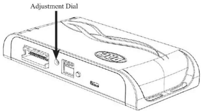
- Verify that all SWC buttons are functioning properly for both the aftermarket radio and OnStar. To adjust OnStar volume, press the OnStar button on the mirror then use the volume buttons on the SWC, or the adjustment dial on the side of the module to adjust the level. When you hear a chime during this process it means you have reached the farthest minimum / maximum level.
- Pressing the OnStar button on the rearview mirror will turn off the rear speakers and allow the OnStar audio to be heard in the two front speakers. The OnStar active LED 2 will also turn on. When OnStar disconnects, the radio will un-mute or turn back on and the OnStar LED will turn off. Pressing the VR / OnStar button on the steering wheel will also activate OnStar.
- Turn off vehicle and remove key. RAP will be active and keep the radio on for 10 minutes or until any door is opened.
- The LED 1 and radio will turn off when RAP turns off or until any door is opened.
- Use the 4-position selector switch located on the side of the CMX chime module to select the best chime output volume for your specific installation. Setting 1 being loudest and 4 being softest.
![graph TD A["CMX chime module"] --> B["Switch 1"] A --> C["Switch 2"] B --> D["Battery"]](/content/2026/05/993896/images/8520628fe5bed21326bb1019a3e7bd4a3016a3d4838055e1d04d4668eca59594.jpg)
Rear Seat Entertainment (RSE); If equipped
Using the Radios Dual Zone Source

- Press the power button to turn the RSE Controls on. When Radio is displayed on the RSE Controls, the aftermarket radios rear speaker output will be heard through the headphone jacks. Putting the aftermarket radio into dual zone mode should change the output level of the rear speakers to a fixed level. This allows precise user adjustment from the level knobs on the RSE Controls (refer to aftermarket radio owners manual for model specific dual zone operation).
- The seek arrows and PROG button will control the radio as programmed by the SWC interface. These buttons are mapped to the SWC buttons as stated above.
- Pressing the SRCE button will toggle between the Factory XM tuner and the Radio as the RSE source. Pressing the power button will turn the RSE Controls off as well as turning the key off. The seek arrows and PROG button will continue to operate as stated (with the exception of SRCE which has no function) when the Rear Seat Controls are turned off.
Rear Seat Entertainment (RSE); If equipped
1. Vehicles equipped with an overhead screen only:
In this application the GMRVD2 must be used in order to feed A/V into the factory screen from an aftermarket head unit (head unit must support A/V out). With the GMRVD2, A/V will be passed from the aftermarket head unit to the rear screen and audio can be heard through the headphones. The GMRVD2 will also pass the Auxiliary inputs on the rear of the center console to the aftermarket head unit.
2. Vehicles equipped with an overhead screen AND headrest monitors:
In this application the headrest monitors will function independently from the overhead monitor. Neither video or audio can be passed to or from the headrest monitors. The overhead monitor will function exactly as described in #1.
OnStar Volume Adjustment for Vehicles w/o SWC
- When OnStar is active use the adjustment dial on the side of the module to raise or lower the OnStar volume to the desired level.
RadioPRO PC App
Firmware Updates
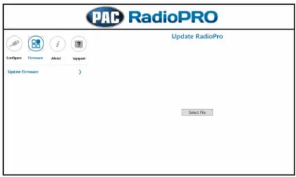
The RadioPRO PC app will allow you to update the interface with new firmware as it becomes available. Please visit https://pac-audio.com/firmware-updates/ for available updates.
Connect the interface to your PC and select "Firmware", then "Update Firmware". Now select "Select File". Finally, browse to the place where you saved the file and select it. This will begin the updating process. Once finished, disconnect the interface from the PC and test operation.

Technical Support
Email: support@PAC-audio.com
Toll Free: 866-931-8021
Standard / International: 727-592-5991

- INTRODUCTION AND FEATURES
- IMPORTANT NOTES
- MODULE LAYOUT
- INSTALLATION STEPS
- IF YOUR BRAND IS NOT LISTED ABOVE, PLEASE USE "ALL OTHER BRANDS
- PROGRAMMING BUTTON AND ADJUSTMENT DIAL FUNCTIONS
- PLEASE NOTE
- DEFAULT STEERING WHEEL CONTROL PROGRAMMING
- OPTIONAL STEERING WHEEL CONTROL PROGRAMMING
- FACTORY MODE
- AFTERMARKET MODE
- OPTIONAL STEERING WHEEL CONTROL PROGRAMMING (CONT.)
- TESTING AND VERIFICATION
- REAR SEAT ENTERTAINMENT (RSE); IF EQUIPPED
- VEHICLES EQUIPPED WITH AN OVERHEAD SCREEN ONLY
- VEHICLES EQUIPPED WITH AN OVERHEAD SCREEN AND HEADREST MONITORS
- ONSTAR VOLUME ADJUSTMENT FOR VEHICLES W/O SWC
- RADIOPRO PC APP
- FIRMWARE UPDATES
- TECHNICAL SUPPORT
Brand : PAC
Model : RP5-GM32
Category : Car kit