
DU6675 - Video projector VIVITEK - Free user manual and instructions
Find the device manual for free DU6675 VIVITEK in PDF.


| Product Type | Video Projector |
| Display Technology | DLP |
| Native Resolution | 1920 x 1200 (WUXGA) |
| Brightness | 6000 ANSI Lumens |
| Contrast Ratio | 10,000:1 |
| Lens | Motorized zoom and focus |
| Lamp Life | 2000 hours (standard), 2500 hours (eco) |
| Dimensions (W x D x H) | 19.4 x 15.0 x 5.8 inches |
| Weight | 30.9 lbs (14.0 kg) |
| Power Consumption | 480W (standard), 0.5W standby |
| Inputs | HDMI, VGA, Composite, USB, RJ45 |
| Keystone Correction | Vertical and horizontal |
| Built-in Speaker | 10W mono |
| Noise Level | 37 dB (standard), 32 dB (eco) |
| Maintenance | Clean air filter every 100 hours, replace lamp when needed |
| Safety | Overheat protection, auto power-off when no signal |
| Spare Parts & Repairability | Lamp and filter kits available; replaceable components |
Frequently Asked Questions - DU6675 VIVITEK
User questions about DU6675 VIVITEK
0 question about this device. Answer the ones you know or ask your own.
Ask a new question about this device
Download the instructions for your Video projector in PDF format for free! Find your manual DU6675 - VIVITEK and take your electronic device back in hand. On this page are published all the documents necessary for the use of your device. DU6675 by VIVITEK.
USER MANUAL DU6675 VIVITEK
natural_image
Line drawing of a projector with a circular lens and decorative patterns (no text or symbols)Table of Contents
Copyright....4
Important Safety Guidelines....5
FCC NOTIFICATION....5
CE NOTIFICATION....5
NOTIFICATION (Canada)....5
AC Power Cord for North/Middle/South and Taiwan....5
Disposal of Old Electric and Electronic Equipment....6
Important Recycling Instructions....6
Installation and Use Notice ....6
Introduction....7
Product Features ....7
Packing Checklist....8
Projector Overview....9
Front-right View 9
Rear-right View 9
Bottom View....10
Control Panel 11
Terminal Panel Features 12
Remote Control....13
Installation and Setup....14
Precautions for Installation....14
Caution for Ceiling Mounting Installation....15
Upward or Downward Installation....16
Installing or Removing the Optional Lens....17
Installing the Optional Color Wheel 18
Remote Control and Operation Range 19
Turning On the Projector....20
Turning Off the Projector....21
Adjusting Projected Image Position 22
Adjusting the Focus and Zoom 23
Making Connections 24
Connecting to the Screen Trigger 26
Connecting to External HDBaseT Transmitter 27
CONVENIENT FEATURES....28
Changing the OSD Language....28
Selecting an Input Source....28
Changing Lamp Power 29
Freezing a Picture....29
Blanking the Image 29
Correcting Keystone Distotion ....30
Preventing the Unauthorized Use of the Projector....31
Using the Control Panel Lock....31
Using the Security Lock....31
Using the Physical Lock 32
Getting Information ....32
Using On-Screen Display....33
Navigating the OSD 33
Menu Tree....34
OSD Operation - PICTURE 37
OSD Operation - SIGNAL....40
OSD Operation - SETUP ....41
OSD Operation - INSTALLATION 45
OSD Operation - SERVICE....48
Maintenance....49
Replacing the lamp 49
Replacing the Lamp....50
Cleaning the projector....51
Specification 53
Product Dimensions....54
Supported Signal Input Timing....55
Configurations of Terminals....56
DU6675 Lens Series 58
Troubleshooting ....59
Indicator Messages....59
Common Problems and Solutions ....60
About the Vivitek Support 62
Copyright
Copyright
The User's Manual (including all pictures, illustrations and software) is protected by the international copyright right law. All rights are reserved. No duplication of the manual or any content included in the manual is allowed without the written consent of the manufacturer. Vivitek is the trademark of Vivitek Corporation. ©All rights reserved. 2015
Disclaimer
The information in the manual is subject to change without notice.
The manufacturer does not provide any statement or warranty of the contents in the manual and clearly give up the implied warranties of merchantability and of fitness for a particular purpose. The manufacturer reserves the rights to modify the publication and change the contents of the materials at any time without notice to any person.
About the Manual
The manual describes how to install and use the DLP projector and is applicable to the end-user. Relevant information (such as illustrations and descriptions) is put on the same page as possible as we can. The format, easy for printing, is convenient for reading and paper-saving which is beneficial to environmental protection. It is suggested printing the page you need.
Important Safety Guidelines
Thank you for purchasing the high quality product!
Read the Manual carefully to obtain the best performance. The Manual provides instructions to use the menu and implement operation.
FCC NOTIFICATION
This device complies with part 15 of the FCC Rules. Operation is subject to the following two conditions: (1) This device may not cause harmful interference, and (2) this device must accept any interference received, including interference that may cause undesired operation.
FCC Warning!
This equipment has been tested and found to comply with the limits for a Class A digital device, pursuant to part 15 of the FCC Rules. These limits are designed to provide reasonable protection against harmful interference when the equipment is operated in a commercial environment. This equipment generates, uses, and can radiate radio frequency energy and, if not installed and used in accordance with the instruction manual, may cause harmful interference to radio communications. Operation of this equipment in a residential area is likely to cause harmful interference in which case the user will be required to correct the interference at his own expense.
CE NOTIFICATION
This is a class A product. In a domestic environment this product may cause radio interference in which case the user may be required to take adequate measures.
NOTIFICATION (Canada)
This class A digital apparatus complies with Canadian ICES-003.
AC Power Cord for North/Middle/South and Taiwan
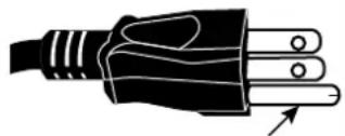
AC Power Cord used in the United States and Canada is listed by the Underwriters Laboratories (UL) and certified by the Canadian Standard Association (CSA).
AC Power Cord has a grounding-type AC line plug. This is a safety feature to be sure that the plug will fit into the power outlet. Do not try to defeat the grounding plug. Should you be unable to insert the plug into the outlet, contact your technical personnel.
natural_image
Illustration of a black electrical plug with three leads and a pointer indicating the cable (no text or symbols present)Disposal of Old Electric and Electronic Equipment
The symbol on your product or the package represents that the product should not be treated as the normal household waste when discarded but should be carried to the recycling location of the waste electric and electronic equipment. The consequence on the environment and human health due to the incorrect disposal of the product can be prevented if it can be ensured that the product is properly discarded. Material recycling is helpful to the protection of natural resources. The symbol is only valid in European Union. If you want to discard electrical and electronic equipment, contact the governmental authorities or your dealer for the correct method of disposal.

Important Recycling Instructions
The lamp of the product contains mercury. The product may contain other electronic wastes and may pose risk if not discarded properly. Abide by the local, state/provincial or federal laws of recycling or discarding.
For more information, please visit the website and contact Electronic Industries Alliance (EIA) on WWW.EIAE.ORG. Please visit WWW.LAMPRECYCLE.ORG for the specific disposal information of lamps. Hg
Installation and Use Notice
- Read and keep the description properly.
- Pay attention to all warnings.
- Follow all guidelines and descriptions.
- Do not use the equipment near water.
- Do not install the equipment near the thermal source, such as the heater, radiator, furnace or other equipment that will generate heat (including the amplifier).
- Use dry clothes to clean only.
- Do not obstruct any vent. Carry out installation according to the guidelines of the Manufacturer.
- Do not destroy the safety protection function of polarized or grounding plugs. A polarized plug has one wide and one narrow blade. The grounding plug has two blades and one grounding blade. The wide blade or grounding blade is provided for the safety concerns. If the plug provided does not match the outlet, contact the electrician to change the old outlet.
- Prevent the power cord from being treaded or pressed, especially the power cord on the plug, outlet and the connection between the power cord and the equipment.
- Only use the connectors/accessories designated by the Manufacturer.
- Be careful of moving the trolley/equipment and avoid being hurt due to turning-over when using the trolley.
- Unplug the power cord of the equipment if there is a thunderstorm or the equipment will not be used for a long time.
- The authorized maintenance personnel is responsible for all maintenance work. The equipment should be repaired if damaged in any means. (For example, the power cord or outlet is damaged. Liquids splash to the equipment or foreign objects fall into the equipment. The equipment is exposed to rain or humidity. The equipment cannot work functionally or falls.)
- The +12V trigger only outputs 12V DC trigger signal. Do not connect to other power input or output. Otherwise, the equipment may be damaged.
- The packaging materials should be kept properly for the use of transportation.
- Do not look straight at the lens when the projector is running.
Introduction
The User's Manual describes the installation, setup and operation of the DU6675 projector and provides assistance to the installation personnel and the end-user to fully develop the performance of the projector. Vivitek has made every efforts to ensure that the information in the Manual is correct at the time of printing. The contents may be frequently updated due to the continuously product improvement and customer feedback.
You can find the latest version of the Manual and the manual of other Vivitek products on www.vivitekcorp.com.
Product Features
Vivitek DU6675 has the cutting-edge technique and creative dual-lamp optical engine to provide the native high resolution as well as clear, brilliant and vivid pictures.
Main Characteristics and Advantages of the Product Series:
- The DLP system with the high performance digital micromirror device (DMD) in conjunction with the advanced thermal management technology provide the excellent projecting performance and reliability.
- The advanced dual-lamp optical engine as well as the single-lamp, dual-lamp, normal, energy-saving and Custom Lamp Power mode offer the convenience for installation. The power of lamps can be adjusted via Custom Lamp Power to make it easier for the installation personnel to fine-tune the edge blending brightness for multi-projectors application.
- With the lamp switching feature, the projector can automatically select the lamps less used when turned on.
- The projector has the replaceable color wheel and smart color wheel detection, can automatically detect and switch the parameter of corresponding color wheels and can be used in conjunction with the color wheel of high brightness or beautiful hues. It is applicable to the single projector.
- The interchangeable lens design allows the user to easily and quickly change the suitable lens by pressing the Lens Release button.
- With the complete series of motorized projection lenses, the horizontal shift, focusing and zooming of lenses can be electrically controlled. The throw ratio ranges from 0.7:1 to 8.5:1 and is suitable to be used in most applications.
- The high performance video processor can be used in progressive and interlaced scanning of the video inputs and video denoising.
- The complete input terminal support many input signals, such as HDMI, DVI-D, HDBase T/LAN, VGA, RGBHV, YPbPr, VIDEO and S-VIDEO, etc.
- With the built-in HDBase T signal reception, HDBase T transmitter can send high quality video and control signals through the single RJ45 cable.
- Many 3D display format is supported, such as Frame Sequential, Top/Bottom, Side by Side and Frame Packing.
- The synchronization of DLP Link and 3D IR are supported.
- With the high efficient power switch, the power consumption less than 0.5W at the standby mode.
Packing Checklist
The following items are included in the packaging box of the DU6675 projector. If any loss or damage to any item, contact your dealer or the Vivitek customer service center.

natural_image
Illustration of a coiled electrical plug with terminal connectors (no text or symbols)AC power cord (For China)

AC power cord (For US)

AC power cord (For EU)

natural_image
Coiled electrical cable with two connectors (no text or symbols visible)VGA signal cable Color-optimized of the wired remote control

natural_image
Simple line drawing of a rope tied with a loop (no text or symbols)Cablebf the wired remote control

color wheel
natural_image
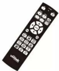
Black remote control with standard buttons and a 'wQlink' logo (no readable text beyond branding)IR remote control

Anti-thief screw for Lens installation (M4)
User's manual disc

RoHS card (China)
Qualification certificate (China)
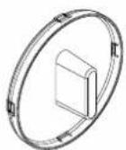
Lens hole cap (Installed)
Projector Overview
Front-right View

1. Lamp Cover
Remove cover to replace lamp or color wheel.
2. Lens Hood
Remove lens cap before use.
3. Control Panel
Press the button to operate the OSD menu or adjust the lens settings, refer to OSD controls.
4. LED Indicator
Displays current projector status such as power, temperature and lamp.
5. Front IR Receiver
Receives for IR signals from remote control.
6. Lens Release Button
Press the Lens Release button before removing the lens.
7. Intake Vent
Lamp cooling vent – do not obstruct.
8. Anti-thief Screw hole
The anti-thief screw can be fasten to prevent Lens removing.
9. Height Adjuster
Adjust level of projector.
10. Intake Vent / filter
The fans pull cool air to the projector for system cooling.
11. I/O Connector Panel
Connect to various input, control or output terminals to the projector.
Rear-right View

12. Rear IR Receiver
Receives for IR signals from remote control.
13. Rear Intake Vent / filter
Rear cooling intake – do not obstruct.
14. Kensington Lock
Attach the projector to a permanent object with the Kensington slot and a security cable.
15. Security Chain Lock
Attach the projector to a permanent object using a security cable.
16. Carrying Handle
Pull up the handle when carrying the projector.
Important:
Grill openings on the projector allow for good air circulation, which keeps the projector lamp cool. Do not obstruct any of the grill openings
Bottom View

Control Panel


Zoom
Increase or decrease image size.
Focus
Focus the projected image.
Up/Down/Left/Right Cursor
Use the bottom to move the projected image up, down, left or right.
MENU
Press the button to display OSD or exit the OSD menu.
Up/Down/Left/Right Cursor
Use the buttons to navigate the OSD or select the OSD option.
ENTER
Press the button to select or change settings in the OSD.
CANCEL
Exit the OSD menu.
Power
Press the button to turn the projector on (main power switch must be turned on first) or press to place the projector at standby mode.
SOURCE
Select the input source.
AUTO
Auto Sync to optimize image size, position, and resolution.
Terminal Panel Features

LAN/HDBaseT
Connect a LAN cable (Cat5/Cat6, not supplied) from a computer, network device, or HDBaseT transmitter.
DVI-D
Connect the DVI-D cable (not supplied) from a DVI-D output device.
HDMI
Connect the HDMI cable from a computer or device.
VGA In
Connect a VGA cable (supplied) from a computer.
Service
For service personnel only.
Monitor Out
Connect to a monitor to display the projected content.
BNC (R/Pr, G/Y, B/Pb, H, V)
Connect RGBHV or Component signal from computer or component video enabled device.
Remote
Connect the remote to the projector.
Note for Screen Trigger:
- When the projector is turned on, a control signal (DC 12V) outputs from this terminal.
- Screen controllers are supplied and supported by screen manufacturers.
COMPONENT
Connect a component video cable from a video device to the RCA jacks.
Video In
Connect a composite video cable (not supplied) from a video device to the yellow RCA jack.
S-Video
Connect a commercially available S-video cable from a video device.
Screen Trigger
When connected to the screen through a commercially available cable, the screen deploys automatically on start up of the projector. The screen retracts when the projector is powered off (see notes below).
AC In
Connect the supplied power cable to AC outlet.
Power Switch
Turn on/off AC power of the projector.
Remote Control

| Label Description | ||
| 1 | Status LED Lights w | when the remote control is used |
| 2 | ON Turn the projector | or on at standby mode |
| 3 | OFF Turn the projector off (standby mode) | |
| 4 | ZOOM + Increase the projection image size | |
| 5 | ZOOM - Reduce the projection image size | |
| 6 | FOCUS+ Focus the projection image | |
| 7 | FOCUS- Focus the projection image | |
| 8 | TEST PATTERN Display the Test Pattern menu for selection | |
| 9 | LENS SHIFT Adjust lens shift range | |
| 10 | UP | Move OSD cursor up |
| 11 | RIGHT | Move OSD cursor right or enter submenu |
| 12 | DOWN | Move OSD cursor down |
| 13 | LEFT Move OSD cursor right or enter submenu | |
| 14 | ENTER | Freeze/unfreezes the projected image picture |
| 15 | MENU | Display OSD main menu |
| 16 | RETURN | Return to last OSD page or exit menu |
| 17 | INPUT | Select the input source |
| 18 | PICTURE | Display picture menu |
| 19 | NETWORK | Display network setting menu |
| 20 | AUTO | Auto adjustment for phase, tracking, size, position |
| 21 | ASPECT | Set up aspect ratio of the projected image |
| 22 | BLANK | Blank the image or press again to display the imaged |
| 23 | OVERSCAN | Enable or disable the overscan function |
| 24 | FREEZE | Freeze/unfreeze the projected image |
| 25 | LAMP MODE | Display the Lamp Control menu |
| 26 | 3D MODE | Display the 3D Mode menu |
| 27 | INFO. | Display the Information menu |
| 28 | LIGHT | Illuminates the buttons on the remote control for 10 sec. |
| 29 | Wire remote jack | Connect to WIRED REMOTE terminal on the projector |
Installation and Setup
Precautions for Installation
Caution:
Ceiling installation must be done by a qualified professional. Contact your dealer for more information. It is not recommended you install the projector by yourself.
Place the projector in a horizontal position.
The tilt angle of the projector should not exceed 15 degrees, nor should the projector be installed in any way other than the desktop and ceiling mount, otherwise lamp life could decrease dramatically, and may lead to other unpredictable damages.

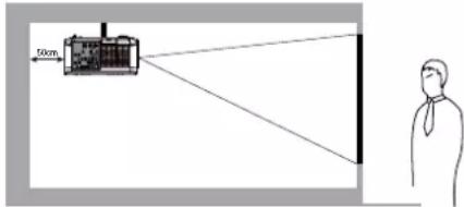
Allow at least 50 cm clearance around the exhaust vent.


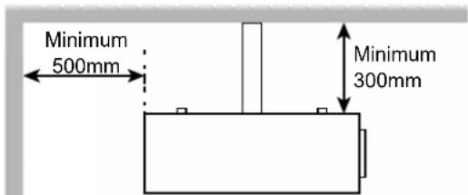
- Ensure that the intake vents do not recycle hot air from the exhaust vent.
- When operating the projector in an enclosed space, ensure that the surrounding air temperature within the enclosure does not exceed operation temperature while the projector is running, and the air intake and exhaust vents are unobstructed.
- All added enclosures should pass a certified thermal evaluation to ensure that the projector does not recycle exhaust air, as this may cause the device to shutdown even if the enclosure temperature is with the acceptable operation temperature range.
Caution for Ceiling Mounting Installation
When installing the projector other than desktop front or rear installation, please read below notice carefully. mounting installation.
For ceiling mounting installation, please use UL Listed ceiling mounts and M4 screws, maximum depth of screw: 12 mm, the distance from wall to projector must be kept 30cm at least for proper ventilation.
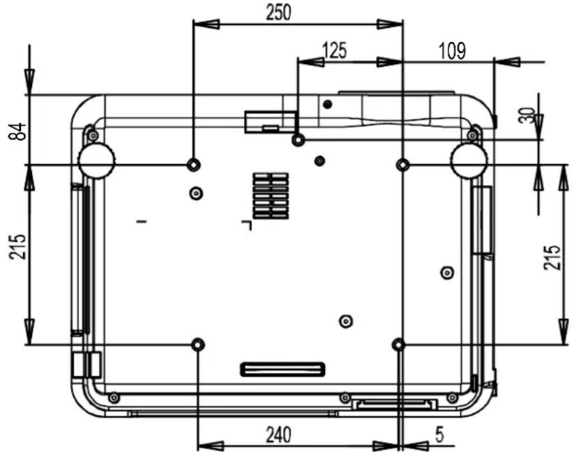
Projector Installation
The high quality display effect can be guaranteed only when the projector is correctly installed. Generally, the light source facing the screen should be reduced or eliminated as much as possible. The contrast of the image will be obviously reduced if the light directly shines on the screen, such as the beam from windows or the searchlight cast on the image. The image may become faded and not bright. The available installation options as below.
Desktop Front
Install the projector on the table and project the image forward.

natural_image
Simple line drawing of a person observing a small object on a table, with no text or symbols present.Desktop Rear
Install the projector on the table and project the image from rear.

Ceiling Front
Mounting the projector on the ceiling and project the image forward.

natural_image
Simple line drawing of a person observing a small object from a perspective cone (no text or symbols)Ceiling Rear
Mounting the projector on the ceiling and project the image from rear.
Upward or Downward Installation
The projector can be installed in addition to the desktop and installed in the ceiling, but also can be mounted up or down for upward or downward projection. When the projector is projected upward or downward, please set Projection Mode (SETUP->Projection Mode) to Upward Front or Downward Front. Refer to the following illustration to set Projection Mode.
Please note that lamp life may be reduced, contact your local dealer for more information

Note:
- In addition to flip the projected image, the cooling fan will also be adjusted to the corresponding speed in order to maintain proper operating temperature of the projector.
- Incorrect Projection Mode setting may affect hot air exhausting from the projector the heat, high temperature may cause the projector goes into system protection, component damage or lamp damage.
- Brightness decay of upward or downward installation is faster than desktop or ceiling installation. Refer to laboratory test results, Lamp life may be reduced to 50-75% of the life which the projector is installed by Desktop or Ceiling installation. Recommend to regularly check the lamps and the brightness of projected image, please consult your local dealer before the projector is installed upward or downward.
Installing or Removing the Optional Lens
Caution:
Do not shake or place excessive pressure on the projector or the lens components as the projector and lens components contain precision parts.
- When shipping the projector with the optional lens, remove the optional lens before shipping the projector. The lens and the lens shift mechanism may encounter damage caused by improper handling during transportation.
- Before removing or installing the lens, be sure to turn off the projector, wait until the cooling fans stop, and turn off the main power switch.
- Do not touch the lens surface when removing or installing the lens.
- Keep fingerprints, dust or oil off the lens surface. Do not scratch the lens surface.
• Work on a level surface with a soft cloth under it to avoid scratching. - If you remove and store the lens, attach the lens cap to the projector to keep off dust and dirt.
Removing the Existing Lens
- Press and hold Lens Release button, rotate the lens counterclockwise. The existing lens will be disengaged.
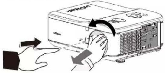
Installing New Lens.
- Align the "↑" symbol on the lens label with the "* " symbol on the top of the body (align to the center of the lens hole) and pull in the lens.
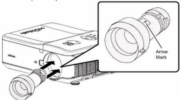
- Pull out the existing lens slowly. 2.

natural_image
Illustration of a projector with a hand operating the front panel (no text or symbols visible)Make sure the lens is pushed into
the holder and turn it clockwise to the "Lock" position. When turning the lens, the "Click" sounds twice to indicate that the lens is completely fixed.

natural_image
Illustration of a projector with a hand operating the front panel (no text or symbols visible)- Check if the lens is fixed successfully by pulling the lens out of the holder gently.
Caution:
- When installing the lens into the projector, be sure to remove the lens cap from the back of the optional lens before installing the optional lens into the projector. Failure to do so will cause damage to the projector.
- Be sure to detach anti-thief screw before removing the projection lens from the projector.
Installing the Optional Color Wheel
The projector comes with a four-segment color wheel installed. An additional six-segment color wheel is an optional. To replace the color wheel (located under the lamp cover adjacent to lamp 1) refer to the following guide.
Note:
- Wait until the lamp house and the color wheel cool off
- Only use the projector on a solid, level surface. Serious injury and damage can occur if the projector is dropped.
Removing the existing color wheel
- Remove the screws (A) on the lamp cover. Lift the lamp cover in the direction of the arrow (B).

- Unscrew the retaining screws (x 4) on the color wheel.
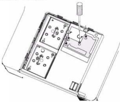
natural_image
Technical line drawing of an electronic device interior with labeled components (no text or symbols)- Lift the color wheel in the direction shown.

Installing the new color wheel
- Insert the new color wheel.

natural_image
Diagram showing a mechanical device with a downward arrow indicating a process or operation (no text or symbols present)- Tighten the 4 screws on the color wheel.
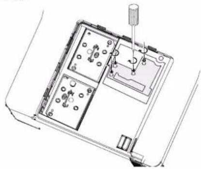
natural_image
Technical line drawing of an electronic device interior with no visible text or symbols- Place the color wheel (A) and tighten the screw on the lamp cover as below illustration (B).

Note:
- Keep the unused color wheel in the zipper bag in which the 6-segment color wheel was packaged. This bag prevents dust from falling or collecting on the color wheel.
Remote Control and Operation Range
Inserting the Remote Control Batteries

natural_image
Diagram of a mechanical component with a blue arrow indicating direction (no text or symbols)
natural_image
Illustration of a remote control device with blue arrows indicating rotation or change (no text or symbols)
natural_image
3D diagram of a mechanical component with an arrow indicating direction (no text or symbols)- Remove the battery compartment cover by sliding the cover in the direction of the arrow.
- Place two AA batteries with the correct polarity.
- Slide on the cover as the arrow in the illustration.
Battery installation instructions
- Make sure the battery is installed with the correct polarity.
- Do not use the old and new batteries or the batteries of different types together.
- Remove the battery if the remote control may not be used for a long time to prevent the damage caused by leaks.
Remote Control Operating Range
The remote control uses infrared transmission to control the projector. It is not necessary to point the remote directly at the projector. Provided you are not holding the remote perpendicular to the sides or the rear of the projector, the remote control will function well within a radius of about 10 meters (32 feet) and 15 degrees above or below the projector level. If the projector does not respond to the remote control, move a little closer.

Important:
- Avoid using the projector with bright fluorescent lighting turned on. Certain high-frequency fluorescent lights can disrupt remote control operation.
- Be sure nothing obstructs the path between the remote control and the projector.
- Do not expose the remote control to high temperature or humidity; otherwise, the remote control will not work functionally.
Turning On the Projector
Once the projector is correctly located and the power cable and other connections are in place, it is important that the projector is powered on correctly in order to avoid damage to components and unnecessary wear and tear.
Refer to the following guide to power on the projector.
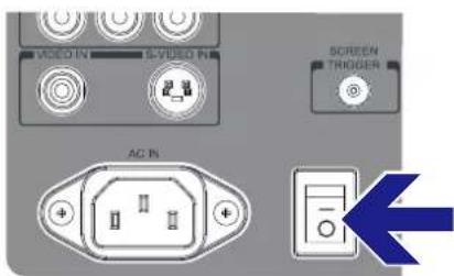
- Connect the power cable (A). Press the main power switch to the on ( I ) position as shown (B), the Power LED lights orange.

- Press the POWER button on the control panel or ON button on the remote control once, the Power LED flashes green and the internal cooling fan starts.

-
After approximately 10 seconds, the Lamp1 and Lamp2 LEDs light green and the Power LED flashes more rapidly.
-
Once the power LED is lit a solid green, the projector is ready for use.
Note:
- If any of the LEDs remain flashing or blink, there may be a problem with the startup. Please refer to the Troubleshooting section.
Turning Off the Projector
Once the projector is no longer required, it is important to shut it down correctly to avoid damage or unnecessary wear and tear to the projector.
Note:
- Do not unplug the power cable from the wall outlet or projector when the projector is powered on. Doing so may cause damage to the AC IN connector of the projector and (or) the prong plug of the power cable. To turn off the AC power supply when the projector is powered on, use a power strip equipped with a switch and a breaker.
Refer to the following guide to shut down the projector.
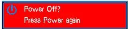
- Press the POWER button on the control panel or OFF button on the remote control once, the Power Off window displays.


- Press the POWER button again on the OSD control panel or remote control to confirm power off. The cooling fans continue to operate and the power LED flashes orange. The cooling fans stop operating when the projector turns off.
-
The projector enters Standby mode when the power LED lights orange.
-
Press the Main Power switch to the off position (O) to turn off the projector.
About Direct Power Off
The projector has a feature called "Direct Power Off". This feature allows the projector to be turned off (even when projecting an image) using a power strip equipped with a switch and a breaker.
Note:
- Before using Direct Power Off, be sure to allow at least 20 minutes immediately after turning on the projector.
Adjusting Projected Image Position
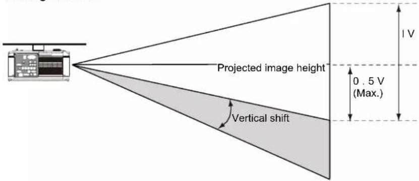
The projector is equipped with powered Lens control features, the projected image can be vertically shifted without moving the projector. The lens shift range is shown in the percentage of the screen height. The project installed on the desk can move up by 50% (0.5V).
Vertical lens shift
The projected image can be moved up by 50% (0.5V) if the project is installed on the desk.

The projected image can be moved down by 50% (0.5V) if the project is installed via a ceiling mount.
Horizontal lens shift
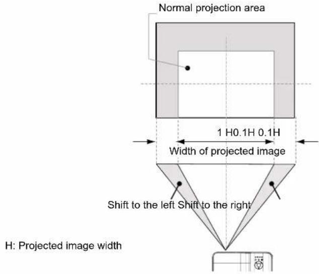
The image can be shifted horizontally to the right or left by 10% (0.1H) without moving the projector.
Adjusting the Focus and Zoom
The focus and zoom can be adjusted manually from the projector control panel or remote control. Refer to the following guides to adjust the focus and zoom manually.
Press the Focus or Zoom button on the control key panel or remote control to adjust the focus or zoom effect using the increase and decrease buttons as required.


Displaying Test Pattern to Align the Projected Screen
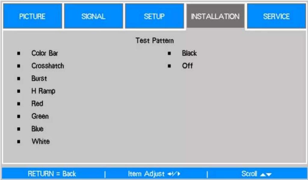
The built-in test pattern is provided for installation and adjustment such as Crosshatch pattern. You can select Test Pattern on OSD or TEST PATTERN button on the remote control to display the test pattern menu, use ◀▶ or ▲▼ to select desired test pattern for alignment, select to Off to exit the test pattern or return to projected image.
Making Connections
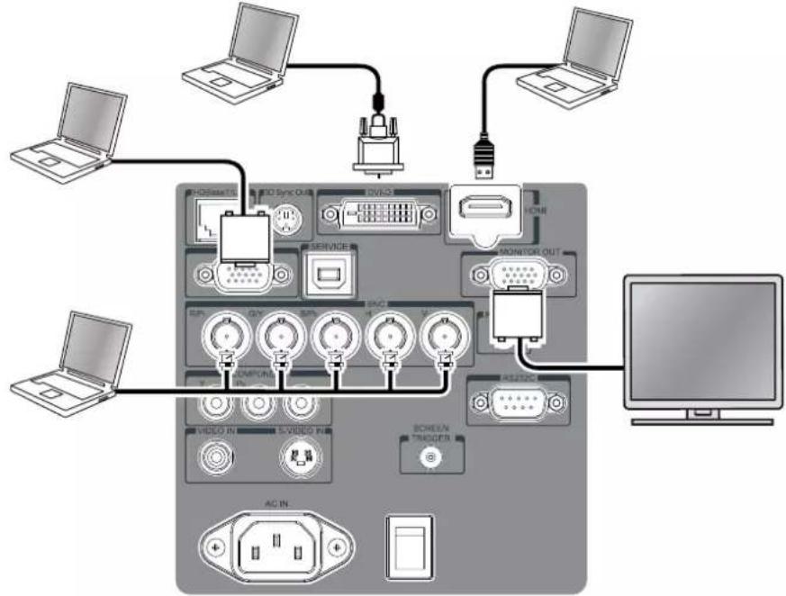
Follow the instructions below to connect DU6675 projector to the video source, external control equipment (if any). When connecting to the equipment, use the correct signal cable to connect to the signal source and ensure that the cable is securely connected. Fasten the nut on the joint and connect the signal source equipment to the projector according to the figure below.
Connecting to Personal Computer
You can connect the PC signal to be projected to the projector through the DVI-D, HDMI, VGA or RGBHV (BNC) cable. If the signal to be input is VGA signal, connect the VGA cable to the external display to simultaneously monitor the projected content.
flowchart
graph TD
    A["Desktop"] --> B["Laptop"]
    A --> C["Laptop"]
    A --> D["Laptop"]
    A --> E["Laptop"]
    A --> F["Laptop"]
    A --> G["Laptop"]
    A --> H["Laptop"]
    A --> I["Laptop"]
    A --> J["Laptop"]
    A --> K["Laptop"]
    A --> L["Laptop"]
    A --> M["Laptop"]
    A --> N["Laptop"]
    A --> O["Laptop"]
    A --> P["Laptop"]
    A --> Q["Laptop"]
    A --> R["Laptop"]
    A --> S["Laptop"]
    A --> T["Laptop"]
    A --> U["Laptop"]
    A --> V["Laptop"]
    A --> W["Laptop"]
    A --> X["Laptop"]
    A --> Y["Laptop"]
    A --> Z["Laptop"]
    A --> AA["Laptop"]
    A --> AB["Laptop"]
    A --> AC["Laptop"]
    A --> AD["Laptop"]
    A --> AE["Laptop"]
    A --> AF["Laptop"]
    A --> AG["Laptop"]
    A --> AH["Laptop"]
    A --> AI["Laptop"]
    A --> AJ["Laptop"]
    A --> AK["Laptop"]
    A --> AL["Laptop"]
    A --> AM["Laptop"]
    A --> AN["Laptop"]
    A --> AO["Laptop"]
    A --> AP["Laptop"]
    A --> AQ["Laptop"]
    A --> AR["Laptop"]
    A --> AS["Laptop"]
    A --> AT["Laptop"]
    A --> AU["Laptop"]
    A --> AV["Laptop"]
    A --> AW["Laptop"]
    A --> AX["Laptop"]
    A --> AY["Laptop"]
    A --> AZ["Laptop"]
    A --> BA["Laptop"]
    A --> BB["Laptop"]
    A --> BC["Laptop"]
    A --> BD["Laptop"]
    A --> BE["Laptop"]
    A --> BF["Laptop"]
    A --> BG["Laptop"]
    A --> BH["Laptop"]
    A --> BI["Laptop"]
    A --> BJ["Laptop"]
    A --> BK["Laptop"]
    A --> BL["Laptop"]
    A --> BM["Laptop"]
    A --> BN["Laptop"]
    A --> BO["Laptop"]
    A --> BP["Laptop"]
    A --> BQ["Laptop"]
    A --> BR["Laptop"]
    A --> BS["Laptop"]
    A --> BT["Laptop"]
    A --> BU["Laptop"]
    A --> BV["Laptop"]
    A --> BW["Laptop"]
    A --> BX["Laptop"]
    A --> BY["Laptop"]
    A --> BZ["Laptop"]
    A --> CA["Laptop"]
    A --> CB["Laptop"]
    A --> CC["Laptop"]
    A --> CD["Laptop"]
    A --> CE["Laptop"]
    A --> CF["Laptop"]
    A --> CG["Laptop"]
    A --> CH["Laptop"]
    A --> CI["Laptop"]
    A --> CJ["Laptop"]
    A --> CK["Laptop"]
    A --> CR["Laptop"]
    A --> CS["Laptop"]
    A --> CT["Laptop"]
    A --> CU["Laptop"]
    A --> CV["Laptop"]
    A --> CW["Laptop"]
    A --> CX["Laptop"]
    A --> CY["Laptop"]
    A --> CZ["Laptop"]
    A --> DA["Laptop"]
    A --> DB["Laptop"]
    A --> DC["Laptop"]
    A --> DV["Laptop"]
Connecting to the Video Device
Connect the video equipment to the input port of the projector via the DVI-D, HDMI, Component Video, Composite Video or S-Video Connector.

Connecting to the Control Equipment
The projector has the following control port for connecting to the control equipment:
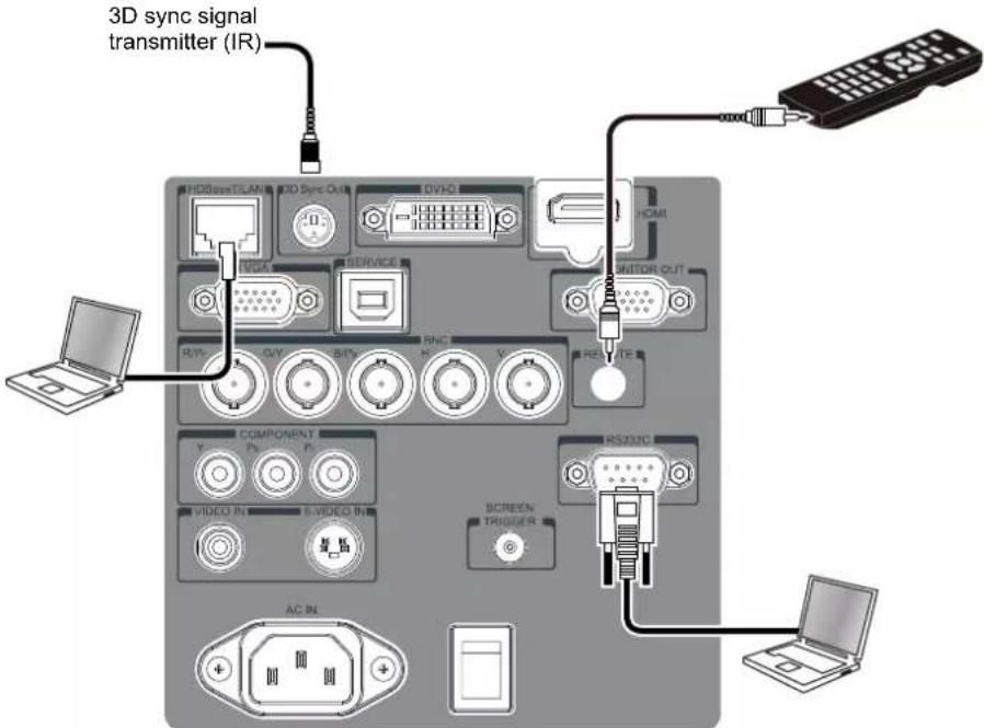
- HDBaseT/LAN (Network control): The projector supports network control via LAN/HDBaseT terminal. LAN and HDBaseT share the port. If only network control is used, you can connect the LAN on the projector to PC or through the local network. Refer to the Remote Communication Guide for more detail information.
- RS-232 (RS-232 control): The projector can be controlled by RS-232 command via connecting the projector to PC or control system through the standard 9-pin serial cable. Refer to the Remote Communication Guide for detail information.
- Wired remote control: If the projector cannot receive the IR signal from the remote control due to the overly long distance or obstacles, you can connect the cable to the IR remote control or the external IR transmitter (optional) via the WIRE port to expand the working range of the remote control.
• 3D Sync Out: Connect to 3D IR sync signal transmitter.
Note:
- If the wired remote control cable or the external IR transmitter is inserted to the incorrect port, such as Trigger, the remote control or the IR transmitter may be damaged. Make sure whether the port is correct.
Connecting to the Screen Trigger
If your projection system includes the Electric projection screen and other 12V trigger device, you can connect these devices to the Trigger and configure the settings on OSD. The projector will output 12V signal when turning on the projector.

Connecting to External HDBaseT Transmitter
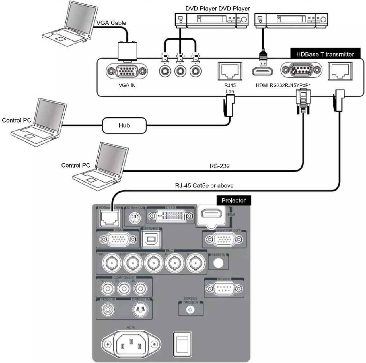
The projector has a built-in HDBaseT receiver. With HDBaseT transmitter (optional), the video, RS-232 and LAN signals can be sent to the projector via a single RJ-45 cable. If HDBaseT you purchased supports to output the IR remote control, the control signals from the IR remote control can be sent to the DU6675 projector via the RJ-45 cable.
flowchart
graph TD
    A["HLHBase T transmitter"] --> B["VGA IN"]
    A --> C["RJ45 Lan"]
    A --> D["HDMI RS232RJ45YPbPr"]
    B --> E["Control PC"]
    C --> F["Hub"]
    D --> G["RS-232"]
    H["VD Driver"] --> I["HDBase T transmitter"]
    J["Control PC"] --> K["Hub"]
    L["Projector"] --> M["AC IN"]
    N["Video In"] --> O["Screen Triggerer"]
    P["Component"] --> Q["RS232C"]
Note:
- The projector supports the video signal, R-232, IR remote control and the reception of the network control signals but do not support Power over Ethernet (PoE).
- Set the INSTALLATION -> RS232 -> Channel on the OSD menu to HDBaseT if you want to use the external HDBaseT transmitter to send the RS232 command to the projector via the RJ45 cable, the baud rate will switch to 9600 automatically.
- If the command is sent via the HDBaseT transmitter, the longest transmission distance is 100 meters. The projector may be interrupted or interfered, or the control signal cannot be sent if the transmission distance is exceeded.
- Use the RJ-45 Cat5e or above cable and avoid entwining. Entwining may cause damage, poor signal transmission, or reduce the transmission distance and degrade the image quality.
CONVENIENT FEATURES
Changing the OSD Language
The project can show the English, French, Spanish, Deutsch, Portuguese, Simplified Chinese, Traditional, Japanese and Korean menu. Press MENU to show OSD then press ◀▶ to select SETUP menu. Press ▲▼ to select the language to be used.

Selecting an Input Source
The Input Source can be selected from the projector's control panel or from the remote control unit. Refer to the following guide to select the Input Source.
- Press SOURCE button on the control panel or INPUT button on the remote control to display Input Selection Menu
- Select the required source using ▲ or ▼ and press ENTER button to confirm the input selection.
- Return to the projected image by pressing RETURN or MENU button.

Changing Lamp Power
There are three Lamp power mode options, Normal, Eco and Custom Lamp Power. The Normal mode is used for every-day standard projection, whereas the Eco mode is used for saving power and lamp life. Custom Lamp power can be used for fine tuning the brightness of the projector. To change the Lamp Mode, refer to the following guides.
-
Press MENU on the projector's OSD control panel or on the remote control to display the main menu. Use ◀or▶ to select SETUP menu.
-
Use ▲ or ▼ to select Lamp power and ◀ or ▶ to set to Normal, Eco mode or Custom Power Level.
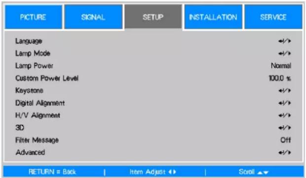
Note:
When the projector is in Eco mode, brightness may be affected.
• Normal Mode: 100% Brightness
• Eco Mode: approx. 80% Brightness
- Custom Power Level: The adjustable range is 100% to 82%(24 steps); this option allows you to adjust lamp power by step.
Freezing a Picture
The projected image can be frozen for short periods of time by using the remote control. This feature is useful for capturing still images from movies or freezing an animation at a particular point. To freeze the projected image, refer to the following guide.
- Press the FREEZE button on the remote control once to freeze the projected image.

- Resume the projected image, press the FREEZE button once more.
Blanking the Image
This feature allows you to temporarily stop projection, the projected image is blanked once BLANK button on the remote control is pressed, press once again to resume the projection.

Correcting Keystone Distotion
When the image is projected either from the top or from the bottom toward the screen at an angle, the image becomes distorted. Use Keystone function to correct the distortion, the adjustable range is approximately+/-30 degree. The following are conditions under which the maximum angle is achieved:
- When the standard lens is used.
- When the lens shift is set to the center point.
• Image is projected in Wide mode.
Use◀ or ▶ to select SETUP\ Keystone to enter Keystone menu.
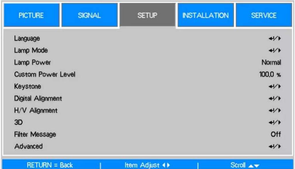
Use ▲ or ▼ to select H Keystone or V Keystone to correct the distortion.
H Keystone: Use ◀▶ to correct the distortion in horizontal direction.

flowchart
graph LR
    A["Top"] --> B["Bottom"]
    B --> C["Bottom"]
V Keystone: Use ◀▶ to correct the distortion in vertical direction

flowchart
graph LR
    A[" "] --> B[" "]
    B --> C[" "]
Preventing the Unauthorized Use of the Projector
Using the Control Panel Lock
This function allows you to lock control panel on the projector; set it to On to lock the control panel. Otherwise, set it to off to unlock the control panel.

Using the Security Lock
The projector has a built-in security feature to lock the OSD control panel and deny remote control operation. The security feature has no default keyword; in the first instance of enabling the security feature, the user must define a keyword.
Locking the projector
To setup the security keyword, refer to the following guide.
- Press MENU on the OSD control panel on the projector or remote control to display the Main menu.
- Use arrow keys to select Security Lock under SETUP\Advanced menu.
- Enter the password by remote control key and use ▲▼◀▶ to set up the PIN code.
- Once the PIN code is set, the PIN code window is displayed when any control button is pressed.
Unlocking the Projector
To unlock the projector, refer to the following guide
- When the projector is locked, either by re-quest during operation or at start up, the locked message is displayed.
- To unlock the projector, enter the previously defined PIN code to activate the projector.


Using the Physical Lock
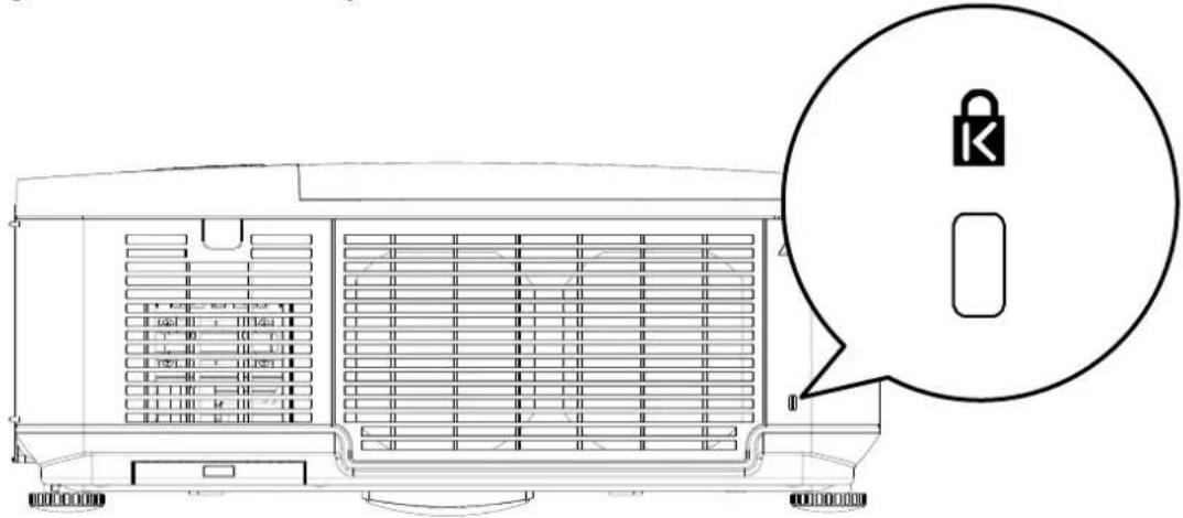
If you are concerned about security, attach the projector to a permanent object with the Kensington slot and a security cable.
Getting Information
The Information screen provides details of the projector status such as lamp status,usage...etc. To access the Information, refer to the following guide.
-
Press MENU on the projector's OSD control panel or remote contro to display the Main Menu. Scroll to the Installation Information menu using ▲or▼ and press.
-
The Information menu is displayed as the default view. The menu items in this screen are for display and cannot be modified.
-
Press CANCEL or MENU to return to the projected image.
| PICTURE | SIGNAL | SETUP | INSTALLATION | SERVICE |
| Model : | DU6675 | |||
| Serial Number : | SN-12345878900000366666 | |||
| Software Version : | MP01-0D06-LD06-RE04-SP03-PC06-9E04-3090 | |||
| Lamp Status | ←/→ | |||
| Source Information | ←/→ | |||
| Usage Time | ←/→ | |||
| Filter Timer Reset | ←/→ | |||
| Factory Reset | ←/→ | |||
Using On-Screen Display
Navigating the OSD
You can use the remote control or the buttons on the top of the projector to navigate and make changes to the OSD. The following illustration shows the corresponding buttons on the remote control and on the projector.

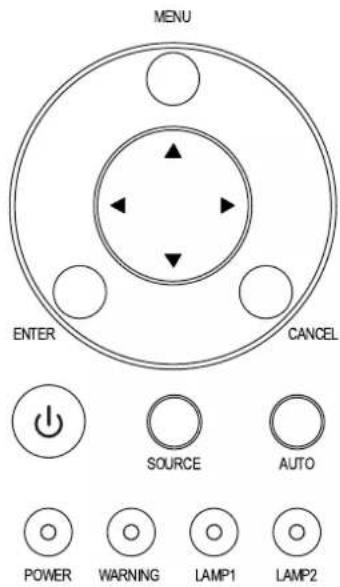
-
To open the OSD, press the MENU button on the OSD control panel or remote control. There are five folders on the menu. Press the cursor ◀ or ▶ buttons to move through secondary menus.
-
Press ▲ or ▼ to select menu items and ◀ or ▶ to change values for settings.
-
Press RETURN to exit a submenu or to close menu.
Menu Tree
Use the following table to quickly find a setting or determine the range for a setting.
| Main Mnu Submenu | ||
| Picture Mode High Bright | ||
| Presentation | ||
| Video | ||
| Brightness | ||
| Contrast | ||
| Saturation | ||
| Hue | ||
| Sharpness | ||
| Color Temperature Native | ||
| 6500K | ||
| 7800K | ||
| 9300K | ||
| Gamma 2.2 | ||
| Film | ||
| Graphic | ||
| Video | ||
| PC | ||
| Picture | Auto Sync S Curve | |
| Advance Setting Input Balance Red Offset | ||
| Noise Reduction | ||
| Dynamic Black On | ||
| Main Mnu Submenu | |||
| Signal | Overscan OffBackground Blue | AutoNativeOnBlackLogo | |
| Language English, Français, Español, Deutsch, Português, 繁體中文,日本語,한국어 | 筒体中文, | ||
| Lamp Mode Dual | SingleLamp 1Lamp 2 | ||
| Lamp Power Normal | EcoCustomer Power level | ||
| Customer Power levelKeystone H Keystone | V Keystone | ||
| Digital Alignment Digital Zoom | Digital PanDigital ScanReset | ||
| H/V Alignment H Zoom | V ZoomH ShiftV ShiftReset | ||
| 3D 3D Format Off | AutoSide by SideTop/BottomFrame Sequential | ||
| SETUP | DLP-Link On | off | |
| 3D Swap Normal | Reverse | ||
| 3D 24Hz Display 96Hz | 144Hz | ||
| Filter Message Off / 100/H 200H / 500 H/ 1000H | |||
| Filter Message Advanced Startup Logo On | Off | ||
| Remote Sensor | Front/BackFrontBackHDBaseT | ||
| Trigger | OnOff | ||
| Control Panel Lock | OnOff | ||
| Security Lock | OnOff | ||
| Installation | Projection Mode | Desktop FrontDesktop RearCeiling FrontCeiling RearUpward FrontDownward Front | |
| Standby Mode | Network StandbyNormal | ||
| High Altitude On/Off | |||
| Auto Power Off | On/Off | ||
| Auto Power On | On/Off | ||
Main Mnu Submenu
| RS232 Baud Rate 38400, 19200, 9600 | |||
| Channel Local | |||
| HDBaseT | |||
| Network IP Address | |||
| Subnet Mask | |||
| Gateway | |||
| DNS | |||
| DHCP On/Off | |||
| Apply No/Yes | |||
| MAC Address | |||
| Lens Control Zoom | |||
| Focus | |||
| Lens shift | |||
| Test Pattern Color Bar | |||
| Cross Hatch | |||
| Burst | |||
| H Ramp | |||
| Red | |||
| Green | |||
| Blue | |||
| White | |||
| Black | |||
| Off | |||
| Model | |||
| Serial Number | |||
| Software Version | |||
| Source Information Active Source | |||
| Pixel Clock | |||
| Signal Format | |||
| H/V Refresh Rate | |||
| Sync Type | |||
| Sync Polarity | |||
| Scan Type | |||
| Video Type | |||
| Lamp Status Lamp 1 On/Off | |||
| Lamp 2 On/Off | |||
| Usage Time Lamp 1 Life Remaining | |||
| Lamp 2 Life Remaining | |||
| Lamp 1 Time | |||
| Lamp 2 Time | |||
| Power On Time | |||
| Filter Timer Reset | OK / Cancel | ||
| Factory Reset | OK / Cancel | ||
OSD Operation - PICTURE

bar
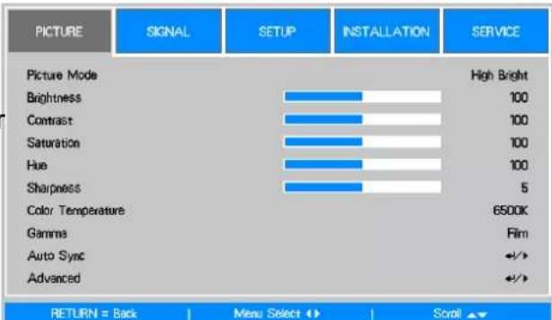
| Category | Value | |---|---| | Picture Mode | High Bright | | Brightness | 100 | | Contrast | 100 | | Saturation | 100 | | Hue | 100 | | Sharpness | 5 | | Color Temperature | 6500K | | Gamma | Film | | Auto Sync | ↔/► | | Advanced | ↔/► | RETURN = Back | Menu Select ↩ | Scroll ▲▼Picture Mode
Use ◀ or ▶ to select a set of preset picture mode.
High Bright: The highest brightness output mode is suitable for the occasion where high brightness is needed.
Presentation: The best image effect is suitable for the presentation or picture.
Video: The best picture mode is suitable for play of the video.
Brightness
Use ◀ or ▶ to increase or decrease the brightness of the image.
Contrast
Use ◀▶ to adjust the contrast of the projected image.
Note:
The brightness and contrast controls affect each other. To obtain the best setting, fine-tune of the brightness setting might be needed after adjustment of the contrast.
Saturation
Use ◀▶ to adjust the saturation level of the color (the higher the level, the higher the saturation.
Hue
Use ◀▶ to adjust the level of hue for reproduction of the true color.
| Main Color | Hue | ||
| R Magenta | ←→ | Yellow | |
| G Yellow | ←→ | Cyan | |
| B Cyan | ←→ | Magenta | |
| C Green | ←→ | Blue | |
| M Blue | ←→ | Red | |
| Y Red | ←→ | Green | |
Sharpness
Use ◀▶ to adjust the sharpness. The purpose of this adjustment is to change the value of the high-frequency detail.
Color Temperature
Use ◀▶ to adjust the color temperature of the projected image, the option can be 6500K, 7800K, 9300K and Native.
Gamma
When the ambient light is too bright and may affect the display of the details in the darker area of the image, you can select from the following gamma options to adjust the chrominance of the image.
2.2: Set the chrominance correction to 2.2.
Film: Set the chrominance correction to approximately Gamma 2.2.
Graphics: This option is used for the PC presentation that needs higher brightness at the cost of the gray scale accuracy.
Video: This is similar to the Film option, but there is a different in the dark area of the image to correspond to the function that the camera uses for creation of the image.
S Curve: S curve is to extend dynamic range while maintaining visual contrast, this reduces contrast in highlights and deep shadows while maintaining or boosting it in middle tones.
Auto Sync
Use this function to execute the Auto Sync for the input signal.
Input Balance

bar
Advanced \ Input Balance | Category | Value | |---|---| | Red Offset | 100 | | Green Offset | 100 | | Blue Offset | 100 | | Red Gain | 100 | | Green Gain | 100 | | Blue Gain | 100 |There are two options for fine tuning Red, Green and Blue color
Offset: These three options will shift the color spectrum for the whole image and change its brightness, if minimal amount of red, green or blue appears in the gray areas, you can adjust the offset of the corresponding color accordingly. By increasing the offset, the image brightness will become lower.
Gain: These three options are used to increase or decrease the range of color input for the entire image. If minimal amount of red, green or blue appears in the gray areas, lower the gain of the corresponding color accordingly. As gain increases, the contrast of the image will become lower.
HSG
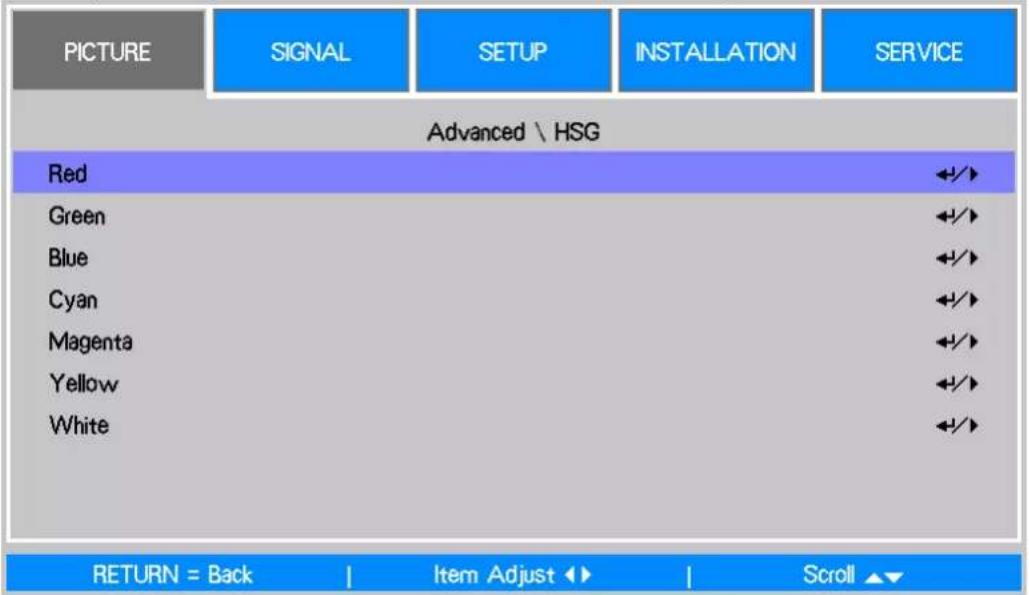
HSG is a function to adjust Hue, Saturation and Gain independently, it allows for specified color adjustments that are more intuitive. You can adjust Hue, Saturation and Gain for Red, Green, Blue, Cyan, Magenta, Yellow and white independently.
Noise Reduction
Use ◀▶ to adjust the noise of the projected image. This function is suitable for removing the noise of the image in interlaced scanning input. Generally, noise reduction can lower the value of the high-frequency detail and make the image softer.
Dynamic Black
Use the ◀▶ function to turn on/off Dynamic Black; it can be used to enhance the black level of the projected image.
OSD Operation - SIGNAL

Input Selection
This function is same as the shortcut key on the remote control. You can use the remote control or this function to select the correct input source.
VGA: Select input source to VGA.
BNC: Select Input source from BNC, the input source can be RGBHV or Component signal from computer or component video enabled device.
DVI-D: Select input source from DVI-D output of the computer or media device.
Video: Select input source from video output of the media device.
S-Video: Select input source from S-Video output of the media device.
HDMI: Select input source from HDIMI output of the computer or media device.
Component: Select input source from component output of the media device.
HDBaseT: HDBaseT input source from the HDBaseT transmitter.
Auto Search
Use the ◀▶ function to turn on/off Auto Search for the input source.
Auto Sync Adjust
You can use this function to set auto synchronization for the input signal.
Auto: The projector memorizes 10 sets of signal sources that you have used lately.
When the Auto option is selected, the projector will choose the signal that you use last.
Always: The auto sync function is executed every time.
Color Space
This function allows you to change the corresponding color space for the input signal. In most cases, the correct color space can be selected automatically by Auto mode. If the selection is not correct, you can use a specific color space forcibly by selecting one of the following options:
Auto: The projector detects the input signal and switches to the corresponding color space automatically.
YCbCr: Set the color space to ITU-R BT.601.
YPbPr: Set the color space to ITU-R BT.709.
RGB-PC: Use the RGB color space and set the black to 0, 0, 0 RGB while set the white to 255, 255, 255 RGB (if an 8-bit image is used).
RGB Video: Use the RGB color space and set the black to 16, 16, and 16 RGB while set the white to 235, 235, 235 (if an 8-bit image is used) to correspond to the luminance value defined in the digital component standard.
VGA Setup
Set the H Total, H Start, H Phase and V Start for the VGA signal display.
Aspect Ratio
This function allows the user to adjust the aspect ratio of the image.
Overscan
Noise may appear on the edge of the projected image, use this function to select Crop to hide the edge of the image or Off to display the original image.
Background
Use this function to specify the image to be displayed on the screen when no signal is input. You can select the Logo, Blue or Black.
OSD Operation - SETUP

Language
Select the familiar OSD Menu language. English, French, Spanish, Deutsch, Portuguese, Simplified Chinese, Traditional, Japanese and Korean.
Lamp Mode

Use the ◀▶ function to select the single-lamp or dual-lamp mode.
Dual: Enable the dual-lamp projection mode.
Single: Use the single-lamp mode for the projection. The lamp is not specified in this mode, the projector selects the lamp that has the least operation hours automatically whenever it is turned on.
Lamp 1: Use Lamp 1 for projection. The system switches to Lamp 2 if Lamp 1 is abnormal in activation.
Lamp 2: Use Lamp 2 for projection. The system switches to Lamp 1 if Lamp 2 is abnormal in activation.
Note:
- In the Lamp 1 or Lamp 2 mode, the projector will switch to another lamp when the set lamp becomes abnormal. The corresponding LED indicator of the lamp will flash simultaneously for seconds and light up.
- When the lamp mode is set to Single, the setting will become valid upon turn-on of the projector next time.
- Quick switch of the lamp mode may affect the life of the lamp. The projector will disable the lamp mode function (highlighted) every time when a switch is conducted till the switch of the lamp mode is completed. The lamp mode options are not available before the switch of the lamp mode is completed receiver via control key button or RS-232 command.
Lamp Power
Use the ◀▶ function to select Normal, Eco or Custom Power Level mode.
Normal: Projection is carried out using the normal lamp power to obtain the brightest projection display.
Eco: Projection is carried out in the energy saving mode to ensure the longest service life of the lamp.
Custom Power Level: In addition to the Normal and Eco modes, the lamp power equal to 100% to 82% of the power in the Normal mode is used for fine tuning of the brightness in the Custom Power Level mode. This function can be used for quick installation and routine maintenance in multi-projector applications. Select this mode to enable the Custom Power Level function.
Custom Power Level
Select this function and use the ◀▶ to adjust lamp power between 100% and 82%, note that this function is valid only when Lamp Power is set to Custom Power Level.
Keystone
When the image is projected toward the screen at angle, the image becomes distorted trapezoid; this function can be used to correct the distortion.
H Keystone: Use ◀▶ to correct the distortion in horizontal direction.
V Keystone: Use ◀▶ to correct the distortion in vertical direction.
Digital Alignment
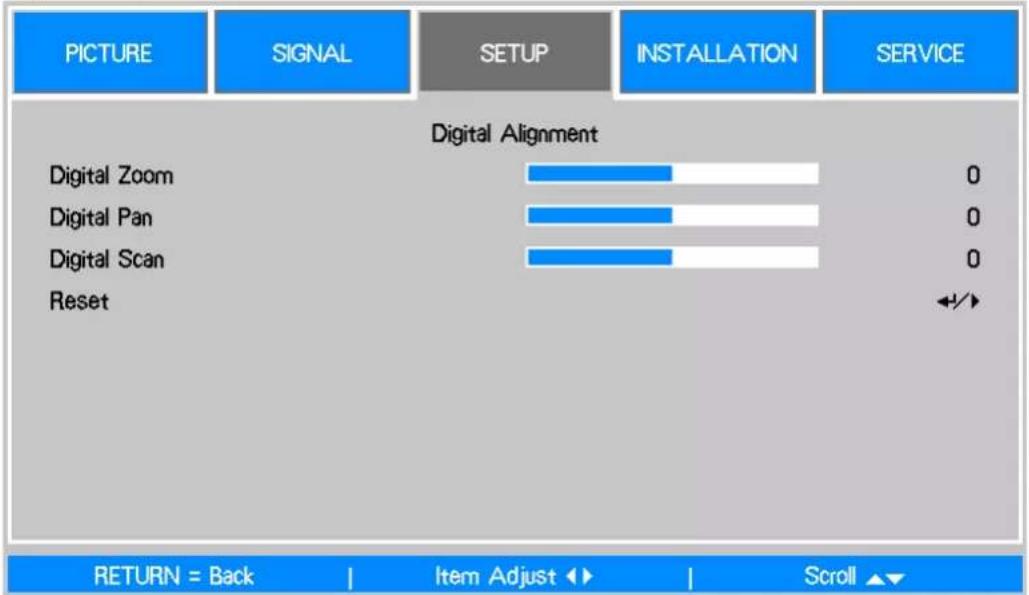
Select this function to enlarge the projected image.
Digital Zoom: Use ◀▶ to enlarge the projected image.
Digital Pan: Use ◀▶ to move the projected image horizontally. This function is only available when the projected image is enlarged.
Digital Scan: Use ◀▶ to move the projected image vertically. This function is only available when the projected image is enlarged.
Reset: Set the Digital Alignment back to the factory default value.
H/V Alignment
H Zoom: Use ◀▶ to narrow the horizontal size of the projected image.
V Zoom: Use ◀▶ to narrow the vertical size of the projected image.
H Shift: Use ◀▶ to move the narrowed projected image horizontally. This function is only available when the projected image is narrowed.
V Shift: Use ◀▶ to move the narrowed projected image vertically. This function is only available when the projected image is narrowed.
Reset: Set the H/V Alignment back to the factory default value.
3D
Set the 3D format and 3D sync signal. The projector detects the signal type and displays the available options for settings; the unavailable option is grayed out. Before performing the 3D setting, ensure that the input signal is connected. When there's no input signal, 3D setting can not be performed.
3D Format
Select this option and press the Enter button to enable 3D replay and set 3D option.
Off: Turn off the 3D Display Mode. When Auto, Side by Side, Top/Bottom or Frame Sequential is selected, the 3D mode will be turned on. To turn off the 3D Mode, select "Off" and press the Enter button.
Auto: Enable the 3D format to automatically detect the formats of Side by Side, Top/Bottom and Frame Sequential. This function may only be enabled for the input signal below:
- The input signal is HDMI 1.4 3D.
- The HDMI 1.4 3D signal connects to the projector through HDBaseT transmitter.
Side by Side: Manually switch the 3D Format to Side by Side. This option is only applicable to the HDMI input signal or the HDMI signal sent using HDBaseT transmitter.
Top/Bottom: Manually switch the 3D Format to Top/Bottom. This option is only applicable to the HDMI input signal or the aforementioned signal sent through the HDBaseT transmitter.
Frame Sequential: Set the format to Frame Sequential.
DLP Link: Set to activate or deactivate the DLP Link sync. signal.
3D Swap: If the 3D imaged viewed through the 3D glasses for the left and right eyes are inverse, set the 3D Swap to "Inverse". If the images are normal, keep the current.
3D 24Hz Display: Set the 3D 24Hz image frame rate to 144fps or 96fps, this option is only applicable when the input signal is 24Hz
Note:
- The projector provides DLP Link and 3D IR sync. After the 3D Mode is enabled, the built-in DLP Link or external 3D IR transmitter can be used to synchronize the signal of the 3D glasses. Or, you may turn off the DLP Link sync signal and only select the external 3D IR transmitter to synchronize the 3D signal.
Caution:
The people listed below shall be aware when watching 3D images:
• Children under six years in age.
• People who are allergic to light, unhealthy and have the history of cardiovascular.
• People who are tired or lack of sleep.
- People who are under the impact of drug or alcohol.
- Normally, it's safe to watch 3D images. However, some people might feel uncomfortable.
• Refer to the guidelines revised and released by the 3D League on December 10, 2008.
• People need to take a break for at least 5 to 15 minutes every thirty minutes or one hour.
Filter Message
This function allows you to set interval time to display a message for cleaning the filter; the available options are Off, 100H, 200H, 500H and 1000H. Please make sure to reset the filter Message after cleaning the filter.
OSD Operation - INSTALLATION
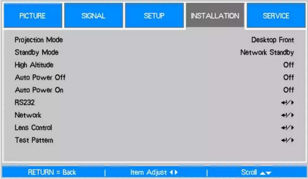
| PICTURE | SIGNAL | SETUP | INSTALLATION | SERVICE |
| Projection Mode | Desktop Front | |||
| Standby Mode | Network Standby | |||
| High Altitude | Off | |||
| Auto Power Off | Off | |||
| Auto Power On | Off | |||
| RS232 | ←/→ | |||
| Network | ←/→ | |||
| Lens Control | ←/→ | |||
| Test Pattern | ←/→ | |||
Projection Mode
Use the ◀▶ function to select a projection mode: Desktop Front, Desktop Rear, Ceiling Front, Ceiling Rear, Upward Front and Downward Front.
Note:
- In addition to flipping the projected image, the cooling fan will also be adjusted to the corresponding speed in order to maintain proper operating temperature of the projector.
- Incorrect Projection Mode setting may affect hot air exhausting from the projector the heat, high temperature may cause the projector goes into system protection, component damage or lamp damage.
- Brightness decay of upward or downward installation is faster than desktop or ceiling installation. Refer to laboratory test results, Lamp life may be reduced to 50-75% of the life which the projector is installed by Desktop or Ceiling installation. Recommend to regularly check the lamps and the brightness of projected image, please consult your local dealer if the projector will be installed upward or downward.
Standby Mode
Use the ◀▶ to select standby mode to Normal or Network Standby.
Network Standby: The projector maintains in the standby status at higher power (<6W) for the projector control via LAN. In this mode, the projector can be turned on via network control system.
Normal: The projector maintains in the standby status at the lowest power (<0.5W), the projector can be turned on using the remote control, RS-232 command.
High Altitude
Use this function to control the cooling fan of the projector, the default setting is OFF. Normally, the projector can operate normally when this function is set to OFF. The projector detects ambient temperature to regulate the cooling fan speed. However, the projector may turn off automatically if it is used in an environment at excessively high temperature or in an area at a high altitude. In this case, please enable this function by setting it to ON and have the cooling fan operate at a higher speed to control the internal temperature of the projector.
Note:
• High Altitude mode is for the place at an altitude of more than 5000 feet.
Auto Power Off
This function is set to OFF by default. When it is set to ON and no input signal is received within 20 minutes, the projector will turn off automatically.
Auto Power On
This function is set to OFF by default. When it is set to ON, the projector will turn on automatically when you connect it to an AC power source next time. You can use this function and the power switch (instead of the remote control) to turn on the projector. Set this function to OFF if you do not need to use it.
RS232
Baud Rate: Set the transmission rate to 38400, 19200, 9600. The setting of the transmission rate is dependent on the length of the RS-232 cable. Low transmission rate is usually set for long transmission cables. If RS-232 is used to control the projector, the signal is unstable or no communication is connected, select a suitable transmission rate.
Channel: The RS232 control command can be sent to the projector through its RS-232 port, the command can also be sent to the projector through the external HDBaseT transmitter to HDBaseT/LAN terminal of the projector. Set the following communication channels before sending the control command.
Local: The RS-232 control command is sent through the RS-232 port on the projector. Select an appropriate baud rate.
HDBaseT: Transmission is conducted from the external HDBaseT transmitter to the RJ-45 port on the projector. The baud rate is switched to 9600.
Network

Use this function to set up network configurations so that you can control the projector via the network.
Press ▲▼ and the Enter button to select Network and network settings:
IP Address: To specify an IP address, press the Enter button to show the IP address input window. Use the ◀▶ button to select the number in the address to be changed. Use the ▲▼ button to increase or decrease the number in the IP address.

Subnet: Set the subnet. The input method is same as the IP address.
Gateway: Set the gateway. The input method is same as the IP address.
DHCP: Set DHCP to ON/OFF. When DHCP is set to ON, the DHCP server will assign an IP address to the projector. The IP address will appear in the IP address window and you don't need to make any input. Otherwise, the domain does not or cannot assign any IP address, and 0.0.0.0 is shown on the IP address window.
Apply: Select this button and press Enter. It takes the projector several seconds to execute the change of the network setting till the following message disappears.
Setting Network configuration, please wait.
For more information about the network control connection and setting, refer to Remote Communication Manual.
Lens Control
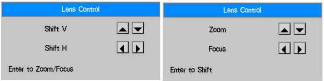
Select this function to open the Lens Control menu for Zoom, Focus or Shift adjustment. You can use the Enter button to switch the Zoom/Focus or Shift menu. Use ◀▶ to adjust zooming and horizontal shift of the lens, or use ▲▼ to adjust focusing and vertical shift of the lens.
Test Pattern
The built-in test pattern is provided for installation and adjustment. You can select Test Pattern on OSD or the TEST PATTERN button on the remote control to display the test pattern menu, use ◀▶ or ▲▼ to select desired test pattern
OSD Operation - SERVICE

Model
Display the Projector model name.
Serial Number
Display the serial number of the projector.
Software Version
Display the software version of the projector.
Source Information
Display the current input source information.
Lamp Status
Display current lamp status of each lamp.
Usage Time
Display the current usage time, estimated remaining lamp life...etc.
Lamp1 Life Remaining: Display estimated remaining lamp1 life.
Lamp2 Life Remaining: Display estimated remaining lamp2 life.
Lamp1 Time: Display current lamp1 usage.
Lamp2 Time: Display current lamp2 usage.
Filter Time: Display the time from last reset of filter timer to now.
Power On Time: Display the total Power-On time of the projector.
Filter Timer Reset
Reset filter timer, please execute this function to synchronize the filter time display after cleaning or changing the filter.
Factory Reset
Use this function to restore the configuration of the menu to the factory default setting. All of the user setting options of the projector will be deleted and restored to the factory default settings.
Maintenance
Replacing the lamp
Depending on the lamp model, the lamp life is affected by the installation method and frequency of the lamp on/off operation. It is suggested to replace the projector lamp when the lamp is used for approximately 2500 hours to ensure high projection quality. In the OSD Menu, the lamp using time can be checked from the "OSD Menu - SERVICE". The lamp should be replaced when the projected image is obviously darkened. Contact your local dealer to purchase the authorized new lamp suitable for your projector.
Note:
- Purchase the lamp module produced by Vivitek. Using the lamp that is not made by Vivitek may affect the performance of the projector or damage the projector.
Lamp Handling Precautions:
- This projector uses a high-pressure lamp which must be handled carefully and properly. Improper handling may result in accidents, injury, or create a fire hazard.
- Lamp life may differ from lamp to lamp and according to the environment of use. There is no guarantee-tee of the same life for each lamp. Some lamps may fail or terminate their life in a shorter period of time than other similar lamps.
- If the projector indicates that the lamp should be replaced, i.e., if LAMP 1 and/or LAMP 2 light up, replace the lamp with a new one IMMEDIATELY after the projector has cooled down. (Follow carefully the instructions in the Lamp Replacement section of this manual.) Continuous use of the lamp with LAMP 1 and/or LAMP 2 lighted may increase the risk of lamp explosion.
- A Lamp may explode as a result of vibration, shock or degradation as a result of hours of use as its lifetime draws to an end. Risk of explosion may differ according to the environment or conditions in which the projector and lamp are being used.
- If a lamp explodes, the following safety precautions should be taken:
- Disconnect the projector's AC plug from the AC outlet immediately. Contact an authorized service station for a checkup of the unit and replacement of the lamp. Additionally, check carefully to ensure that there are no broken shards or pieces of glass around the projector or coming out from the cooling air circulation holes. Any broken shards found should be cleaned up carefully. No one should check the inside of the projector except those who are authorized trained technicians and who are familiar with projector service. Inappropriate attempts to service the unit by anyone, especially those who are not appropriately trained to do so, may result in an accident or injury caused by pieces of broken glass.
- The projection lamp should be replaced when it burns out. It should only be replaced with a certified replacement part, which you can order from your local dealer.
Warning:
- Be sure to turn off and unplug the projector at least 30 minutes before replacing the lamp. Failure to do so could result in a severe burn.
- Safety glasses should be worn when replacing the lamp while the projector is ceiling mounted
Replacing the Lamp
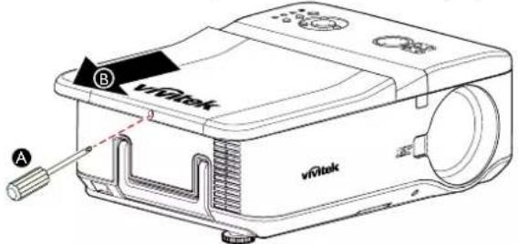
- Remove the screw on the lamp cover (A), and lift the lamp cover as shown (B).
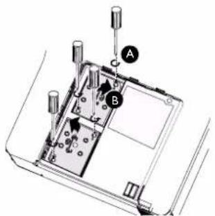
- Loosen the two captive screws on the lamp module (A). Lift the module handle up as shown (B).
- Pull firmly on the module handle in the direction shown to remove the lamp.

natural_image
Technical line drawing of a device interior with two components and upward arrows indicating movement (no text or symbols)- Install the new lamp module(s) and replace the lamp cover.

natural_image
Technical line drawing of a device interior with two components and arrows indicating assembly or installation (no text or symbols)- Tighten the two captive screws on the lamp module.

natural_image
Technical line drawing of a device interior with mounting holes and internal components (no text or symbols)- Place the lamp cover and tighten one screw on the cover as below illustration.

Cleaning the projector
Cleaning the Cabinet
Refer to the following guide to clean the projector cabinet.
- Wipe off dust with a clean dampened cloth.
- Moisten the cloth with warm water and mild detergent and wipe the cabinet.
- Rinse all detergent from the cloth and wipe the projector again.
Caution:
• To prevent discoloration or fading of the case, do not use abrasive alcohol-based cleaners.
Cleaning the Lens
- Apply a little optic lens cleaner to a clean, lint free cloth (do not apply the cleaner directly to the lens).
- Lightly wipe the lens in a circular motion.

natural_image
Illustration of a hand cleaning a projector with a cloth (no text or symbols visible)Caution:
- Do not use abrasive cleaners or solvents.
• To prevent discoloration or fading, avoid getting cleaner on the projector case.
Cleaning the Filters
The projector uses three filters to keep the fans free of dust and other particles, and should be cleaned every 500 hours of operation. In dusty environments, it is recommended to clean the filters more frequently. If the filter is dirty or clogged, your projector may overheat. When the message be-low is displayed, the filters must be cleaned.
Note:
- When the filter message is displayed, please clean all three filters at the same time to synchronize the Filter time display. The Filter Message item should be enabled in the Options menu.
Refer to the following guide to clean the filters.
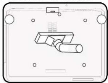
- The left and rear filters can be cleaned as demonstrated in the following images.

natural_image
Technical line drawings of two projector devices, one front view and one side view, showing internal components and wiring (no text or symbols)- The rear exhaust vent can be accessed as shown.
natural_image
Pure technical diagram of a mechanical component without any text, numbers, or symbols- Gently slide the filter holders in the direction shown as below.

natural_image
Diagram of a projector with labeled components and directional arrows indicating motion (no text or symbols)- Lift the filter foams from all three filter holders in the direction shown. Remove them completely from each filter holder and discard.
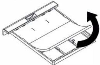
natural_image
Technical line drawing of a mechanical component with an arrow indicating rotational motion (no text or symbols)- Place a replacement foam and press down firmly.

natural_image
Isometric line drawing of a modular panel or storage unit with a black arrow indicating a component (no text or symbols)- Replace the filter holders by pushing gently in the direction shown on below illustration.
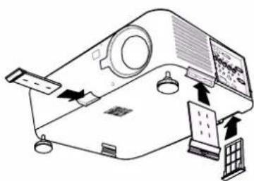
Specification
| Model DU6675 | |
| Display type 1-DLP | |
| 0.67" DMD | |
| Native resolution WUXGA (1920x1200) | |
| Maximum resolution WUXGA (1920x1200) @ 60Hz | |
| Contrast 3000:1 | |
| Lamp life and type 2500/3500 hours (Normal / Eco mode), 280Wx2 | |
| Throw Ratio* 1.73-2.27:1 | |
| Image Size* 40~500" | |
| Projection Distance* 1.83-14.9m(6-49ft) | |
| Projection Lens* F=1.64-1.86f=26-34mm | |
| Zoom Ratio* 1.3X | |
| Aspect Ratio 16:10 Normal4:3 compatible with 16:9 | |
| Lens Shift* 0%~+50%(V); +/-10%(H) | |
| Keystone V: +/-30°; H:+/-30° | |
| Sync V: 48-120Hz | H: 15-90kHz |
| Video compatibility | SDTV (480i/576i), EDTV (480p/576p), HDTV (720p, 1080i/p) |
| I/O Port | HDMI v1.4a, DVI-D, 3D Sync Out, HDBase T / LAN (share with LAN control), RGB In, RGB Out, Component (YPbPr)/RGBHV, Component (RCA*3), Composite (RCA Jack), S-Video (Mini DIN 4pin), RS-232C, Screen Trigger, Wire (wired remote control), USB (for service). |
| Projection Method | Desktop projection, ceiling (front or rear) |
| Size (W x D x W) | 505x194x385mm (excluding the protruding part) |
| Weight | 16.5kg (excluding the lens) |
| Noise level | 35dB/39dB (Dual Lamp Eco/Standard Mode) |
| POWER AC100-240V | 50/60Hz |
| Power Consumption < | 0.5 watts for Off mode. (Power key/Remote power key only)< 6 watts for Network Standby mode. (LAN/RS232/Control Panel only) |
| Accessories AC power | cord, VGA cord, remote control, lens cap, user manual CD. |
* Standard Lens
Product Dimensions

natural_image
Technical line drawing of a mechanical component with dimension标注 (no text or symbols present)
natural_image
Technical line drawing of a mechanical component with dimension标注 (389 mm), showing internal structure and mounting points (no text or symbols beyond measurement)

Supported Signal Input Timing
| Signal type Resolution Frame rate | Component BNC | DVI-D V-S-Video | HDMI | HDBase T | 3D support 3D formal (frame sequential) | Video | |||
| RGBHV YUV RGB YUV | |||||||||
| PC 640 | 480-60 59.93 V - V V - | ||||||||
| 640*480-75 75 | V - V V - V | - | - | ||||||
| 640*480-85 85.01 V | - V V - V | - | |||||||
| 800*600-60 60.32 V | - V V - V V - | ||||||||
| 800*600-75 75 | V - V V - V | - | - | ||||||
| 800*600-85 85.06 V | - V V - V | - | |||||||
| 848*480-60 60 | V - V V - V V - | ||||||||
| 1024*768-60 | 60 | V - V V - V V - | |||||||
| 1024*768-75 | 75.03 V - V | V - V | - | - | |||||
| 1024-768-85 | 85.03 V - V | V - V | - | - | |||||
| 1024-768-120 120 | V - V V - V V - | ||||||||
| 1024-768RB-120 11 | 9.98 | V - V V - V V - | |||||||
| 1280*720-60 | 59.91 V - V | V - V V - | |||||||
| 1280*720-120 | 120 | V - V V - V V - | |||||||
| 1280*768-60 | 59.87 V - V | V - V V - | |||||||
| 1280*800-60 | 59.81 V - V | V - V V - | |||||||
| 1280*800RB-120 | 119.9 | V - V V - V V - | |||||||
| 1280*960-60 | 60 | V - V V - V V - | |||||||
| 1280*1024-60 | 60.02 V - V | V - V V - | |||||||
| 1280*1024-75 | 75.02 V - V | V - V | - | - | |||||
| 1280*1024-85 | 85.02 V - V | V - V | - | - | |||||
| 1440*900-60 | 59.887 | V - V V - V V - | |||||||
| 1400X1050-60 | 59.98 V - V | V - V V - | |||||||
| 1600*1200-60 | 60 | V - V V - V V - | |||||||
| 1680*1050-59.94 | 59.94 V - V | V - V V - | |||||||
| 1920*1200RB-60 | 59.95 V - V | V - V V - | |||||||
| Video | NTSC (M) (3.58, 4.43) | 59.94 | - | - | - | - | - | - | V |
| PAL (B,G,H,I) | 50 | - | - | - | - | - | - | V | |
| PAL (N) | 50 | - | - | - | - | - | - | V | |
| PAL (M) | 60 | - | - | - | - | - | - | V | |
| S E C A M (M) (4.25/4.4) | 50 | - | - | - | - | - | - | V | |
| SDTV | 1440x480i | 60 | - | - | - | V | V | V (HDMI) | - |
| 1440x576i | 50 | - | - | - | V | V | V (HDMI) | - | |
| 480i | 59.94 | - | V | - | - | - | - | V | |
| 576i | 50 | - | V | - | - | - | - | V | |
| EDTV | 480p | 59.94 | V | V | V | V | V | V | - |
| 576p | 50 | V | V | V | V | V | V | - | |
| 1080i | 50 | - V | V V V | V | - | - | |||
| 1080i | 60 | - | V | V | V | V | - | - | |
| 720p | 50 | V | V | V | V | V | V | - | |
| 720p | 60 | V | V | V | V | V | V | - | |
| 1080p | 24 | V | V | V | V | V | - | - | |
| 1080p | 25 | V | V | V | V | V | - | - | |
| 1080p | 29.97 | V | V | V | V | V | - | - | |
| 1080p | 30 | V | V | V | V | V | - | - | |
| 1080p | 50 | V | V | V | V | V | V | - | |
| 1080p | 60 | V | V | V | V | V | V | - | |
Configurations of Terminals
DVI-D
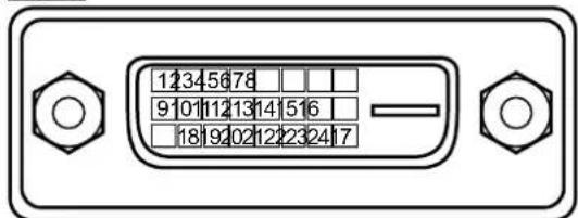
| 1 T.M.D.S. Data 2- Input 13 N.C | ||
| 2 T.M.D.S. Data 2+ Input 14 P5V | ||
| 3 Ground 15 Ground | ||
| 4 N.C 16 HPD | ||
| 5 N.C 17 T.M.D.S. Data 0- Input | ||
| 6 SCL 18 T.M.D.S. Data 0+ Input | ||
| 7 SDA 19 Ground | ||
| 8 N.C 20 N.C | ||
| 9 T.M.D.S. Data 1- Input 21 N.C | ||
| 10 T.M.D.S. Data 1+ Input 22 Ground | ||
| 11 Ground 23 T.M.D.S. Clock+ Input | ||
| 12 N.C 24 T.M.D.S. Clock- Input |
VGA (D-sub 15 pin)
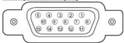
Input
| 1 Red Input | 9 P5V | |
| 2 Green Input | 10 GND | |
| 3 Blue Input | 11 GND | |
| 4 N.C 12 VGA_SDA | ||
| 5 N.C 13 H-Sync | ||
| 6 GND | 14 V-Sync | |
| 7 GND | 15 VGA_SCL | |
| 8 GND | 16 GND |
HDMI(19 pin Type A)
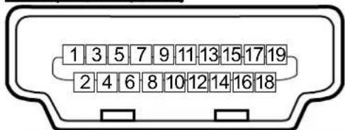
| 1 T.M.D.S. Data 2+ Input 11 Ground | |
| 2 Ground 12 T.M.D.S. Clock C- Input | |
| 3 T.M.D.S. Data 2- Input 13 CEC | |
| 4 T.M.D.S. Data 1+ Input 14 N.C | |
| 5 Ground 15 SCL | |
| 6 T.M.D.S. Data 1- Input 16 SDA | |
| 7 T.M.D.S. Data 0+ Input 17 Ground | |
| 8 Ground 18 P5V | |
| 9 T.M.D.S. Data 0- Input 19 HPD | |
| 10 T.M.D.S. Clock C+ Input |
Serial Control (RS-232, D-sub 9 pin)

| Serial | |
| 1 N.C | |
| 2 RXD | |
| 3 TXD | |
| 4 N.C | |
| 5 Ground | |
| 6 N.C | |
| 7 Short with pin8 | |
| 8 Short with pin7 | |
| 9 N.C | |
3D Sync Out

| 1 Signal |
| 2 Ground |
| 3 VCC(5V) |
Service (USB Type A)

Screen Trigger
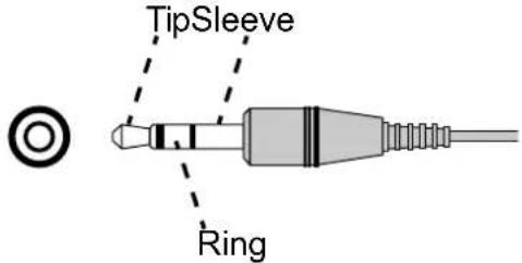
| 1 Tip VCC(12V) | |
| 2 Sleeve- Ground | |
| 3 Ring Signal |
Wired Remote

| 1 Tip VCC(3.3V) | |
| 2 Sleeve- Ground | |
| 3 Ring Signal |
HDBaseT/LAN Terminal (RJ-45)
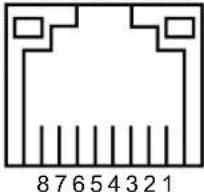
| 1 TX+ |
| 2 TX- |
| 3 TXC |
| 4 Ground |
| 5 Ground |
| 6 RXC |
| 7 RX+ |
| 8 RX- |
DU6675 Lens Series
7 types of optional powered lenses are available for the projector. Contact the authorized dealer of Vivitek for details.
| Part Number | Lens Name F | Number Focal | Length Zoom | Ratio Screen Size | Throw Ratio | |
| D88-UWZ01 | Ultra Wide Zoom | 1.96-2.3 11.3-1 | 4.1mm 1.25:1 | 40"-500" 0.75-0 | 93:1 | |
| D88-WF18501 | Wide Fix 1.85 | 1.6mm --- 40"-500" 0.76:1 | ||||
| D88-WZ01 | Wide Zoom | 1.85-2.5 | 18.7-26.5mm | 1.41:1 | 40"-500" | 1.25-1.79:1 |
| D88-ST001 | Standard Lens | 1.7-1.9 | 26-34mm | 1.3:1 | 40"-500" | 1.73-2.27:1 |
| D88-SMLZ01 | Semi Long Zoom | 1.86-2.48 | 32.9-54.2mm | 1.65:1 40"-500" | 2.22-3.67:1 | |
| D88-LOZ101 | Long Zoom 1 | 1.85-2.41 | 52.8-79.1mm | 1.5:1 | 40"-500" | 3.58-5.38-1 |
| D88-LOZ201 | Long Zoom 2 | 1.85-2.48 | 78.5-121.9mm | 1.55:1 | 40"-500" | 5.31-8.26:1 |
- Above lenses can support to vertical shift 0-50%, horizontal shift ±10% except of D88-WF18501.
- D88-WF18501 is a fixed lens, the vertical and horizontal shift range is 0%, the corners of the projected image may appear shadows or distortion if lens is shifted horizontally or vertically.
Troubleshooting
Indicator Messages
Several indicator messages are used to display the current projector status or alert the abnormal message. The LEDs on the top surface of the projector show the status of the POWER, WARNING LAMP 1 and LAMP 2

POWER

WARNING

LAMP1

LAMP2
Below tables describe the various states of the 4 LEDs.
| LED INDICATOR STATUS PROJECTOR STATUS | |||
| Power Off | AC off | ||
| Red on Standby | |||
| Green on Power on | |||
| Orange blinks Projector is under cooling | |||
| Green blinks Start up | |||
| Warning Off Normal condition | |||
| Red blinks 1 time The lamp cover is open. Check if lamp cover is installed properly. | |||
| Red blinks 2 times The internal temperature is abnormally high. | The temperature around the projector are high, use the projector in an environment with the temperature of lower than 104ircF ( 40ircC ).Air intake may be blocked, relocate the projector to an area with proper ventilation.Internal circuit may be fail, contact the local Vivitek service center. | ||
| Lamp 1 Lamp 2 | Off Lamp is turned off. | ||
| Green on Lamp mode is set to Normal. | |||
| Orange on Lamp mode is set to ECO. | |||
| Green blinks Lamp model is set to Normal, it's warming up or under cooling. | |||
| Orange blinks Lamp model is set to Eco, it's warming up or under cooling. | No lamp is installed or lamp should be replaced, check if the lamp is installed properly.The lamp is burnt out.Contact with your nearest authorized dealer or service center. | ||
| Red blinks | The lamp does not illuminate. | ||
Common Problems and Solutions
These guidelines provide tips to deal with problems you may encounter while using the projector. If the problem remains unsolved, contact your dealer for assistance.
Often the problem is something as simple as a loose connection. Check the following before proceeding to the problem-specific solutions.
- Use some other electrical device to confirm that the electrical outlet is working.
- Ensure the projector is turned on.
- Ensure all connections are securely attached.
- Ensure the attached device is turned on.
- Ensure a connected PC is not in suspend mode.
- Ensure a connected notebook computer is configured for an external display. (This is usually done by pressing an Fn-key combination on the notebook.)
Tips for Troubleshooting
- In each problem-specific section, try the steps in the order suggested. This may help you to solve the problem more quickly.
- Try to pinpoint the problem to avoid replacing non-defective parts.
- For example, if you replace batteries and the problem remains, put the original batteries back and go to the next step.
- Keep a record of the steps you take when troubleshooting: The information may be useful when calling for technical support or for passing on to service personnel.
Image Problems
Problem: No image appears on the screen
- Verify the settings on your notebook or desktop PC.
- Turn off all equipment and power up again in the correct order.
Problem: The image is blurred
- Adjust the Focus on the projector.
- Press the AUTO button on the remote control or projector.
- Ensure the projector-to-screen distance is within the specified range.
- Check that the projector lens is clean.
- Remove the lens cover.
Problem: The image is wider at the top or bottom (trapezoid effect)
- Position the projector so it is as perpendicular to the screen as possible.
- Use the Keystone function to correct the problem
Problem: The image is reversed or upside down
Check the Projection Mode setting on the INSTALLATION menu.
Problem: The image is streaked
- Set the Total dots (H Total) and VGA Setup settings on the SIGNAL menu of the OSD to the default settings.
- To ensure the problem is not caused by a connected PC's video card, connect to another computer.
Problem: The image is flat with no contrast
- Adjust the Contrast setting on the PICTURE menu of the OSD.
- Adjust the Brightness setting on the PICTURE menu of the OSD.
Problem: The color of the projected image does not match the source image.
Adjust the Color temperature and Gamma settings on the PICTURE menu of the OSD.
Lamp Problems
Problem: There is no light from the projector.
- Check that the power cable is securely connected.
- Ensure the power source is good by testing with another electrical device.
- Restart the projector in the correct order and check that the Power LED is green.
- If you have replaced the lamp recently, check the lamp installation and try resetting the lamp connections.
- Replace the lamp module.
- Put the old lamp back in the projector and have the projector serviced if the problem can not be fixed.
Problem: The lamp goes off
- Check if both lamps are installed, projector will enter to protection mode if one of lamp is not installed.
- Press the power button twice to turn off the projector and turn off AC Power, restart the projector again. It's possible that power surges can cause the lamp to turn off.
- Replace the lamp module.
Remote Control Problems
Problem: The projector does not respond to the remote control.
- Direct the remote control towards remote sensor on the projector.
- Ensure the path between remote and sensor is not obstructed.
- Turn off any fluorescent lights in the room.
- Check the battery polarity.
- Replace the batteries.
- Turn off other Infrared-enabled devices in the vicinity.
- Have the remote control serviced.
- Ensure that the remote control code conforms to the projector's code if universal remote control is used.
- Ensure Front or Back remote sensor is turned on (SETUP/Advanced/Remote Sensor).
Projection Lens Problems
Problem: The Zoom or Focus adjustment can not work.
- Check if the lens is installed problem, improper lens installation may cause to lens can not work normally. Please follow the lens installation procedure to check again.
- Relace the other lens to check the problem if the lens is available.
- Contact with service center for the details.
Having the Projector Serviced
If you are unable to solve the problem, you should have the projector serviced. Pack the projector in the original carton. Include a description of the problem and a checklist of the steps you took when trying to fix the problem. The information may be useful to the service personnel. Return the projector to the place you purchased it.
About the Vivitek Support
If you cannot find solutions from this user guideline, please contact us using the contact information below.
North America
Vivitek Service Center
15700 Don Julian Road, Suite B
City of Industry, CA. 91745
U.S.A
Tel: 855-885-2378 (Toll-Free)
Email: T.services1@vivitekcorp.com
URL: www.vivitekusa.com
Europe, Middle East and Africa
Vivitek Service & Support
Zandsteen 15
2132 MZ Hoofddorp
The Netherlands
Tel: +31 20 655 0960
Email: support@vivitek.eu
URL: www.vivitek.eu
China
Vivitek Service Center
VIVITEK after-sales service
Vivitek Corporation, Co., Ltd.
4F., No.186, Ruiguang Rd., Neihu Dist., Taipei City 11491
TEL: 86-28-797-2088
FAX: 86-26-600-2358

- Table of Contents
- Copyright....4
- Important Safety Guidelines....5
- Introduction....7
- Installation and Setup....14
- CONVENIENT FEATURES....28
- Using On-Screen Display....33
- Maintenance....49
- Specification 53
- Product Dimensions....54
- Supported Signal Input Timing....55
- Configurations of Terminals....56
- DU6675 Lens Series 58
- Troubleshooting ....59
- About the Vivitek Support 62
- Copyright
- Disclaimer
- About the Manual
- Important Safety Guidelines
- FCC NOTIFICATION
- FCC Warning!
- CE NOTIFICATION
- NOTIFICATION (Canada)
- AC Power Cord for North/Middle/South and Taiwan
- Disposal of Old Electric and Electronic Equipment
- Important Recycling Instructions
- Installation and Use Notice
- Introduction
- Product Features
- Packing Checklist
- Projector Overview
- Lamp Cover
- Lens Hood
- Control Panel
- LED Indicator
- Front IR Receiver
- Lens Release Button
- Intake Vent
- Anti-thief Screw hole
- Height Adjuster
- Intake Vent / filter
- I/O Connector Panel
- Rear IR Receiver
- Rear Intake Vent / filter
- Kensington Lock
- Security Chain Lock
- Carrying Handle
- Important:
- Control Panel
- Zoom
- Focus
- Up/Down/Left/Right Cursor
- MENU
- ENTER
- CANCEL
- Power
- SOURCE
- AUTO
- Terminal Panel Features
- LAN/HDBaseT
- DVI-D
- HDMI
- VGA In
- Service
- Monitor Out
- BNC (R/Pr, G/Y, B/Pb, H, V)
- Remote
- Note for Screen Trigger:
- COMPONENT
- Video In
- S-Video
- Screen Trigger
- AC In
- Power Switch
- Remote Control
- Installation and Setup
- Precautions for Installation
- Caution:
- Place the projector in a horizontal position.
- Allow at least 50 cm clearance around the exhaust vent.
- Caution for Ceiling Mounting Installation
- Projector Installation
- Desktop Front
- Desktop Rear
- Ceiling Front
- Ceiling Rear
- Upward or Downward Installation
- Please note that lamp life may be reduced, contact your local dealer for more information
- Note:
- Installing or Removing the Optional Lens
- Removing the Existing Lens
- Installing New Lens.
- Installing the Optional Color Wheel
- Removing the existing color wheel
- Installing the new color wheel
- Remote Control and Operation Range
- Inserting the Remote Control Batteries
- Battery installation instructions
- Remote Control Operating Range
- Turning On the Projector
- Turning Off the Projector
- About Direct Power Off
- Adjusting Projected Image Position
- Vertical lens shift
- Horizontal lens shift
- Adjusting the Focus and Zoom
- Displaying Test Pattern to Align the Projected Screen
- Making Connections
- Connecting to Personal Computer
- Connecting to the Video Device
- Connecting to the Control Equipment
- Connecting to the Screen Trigger
- Connecting to External HDBaseT Transmitter
- CONVENIENT FEATURES
- Changing the OSD Language
- Selecting an Input Source
- Changing Lamp Power
- Freezing a Picture
- Blanking the Image
- Correcting Keystone Distotion
- Preventing the Unauthorized Use of the Projector
- Using the Control Panel Lock
- Using the Security Lock
- Locking the projector
- Unlocking the Projector
- Using the Physical Lock
- Getting Information
- Using On-Screen Display
- Navigating the OSD
- Menu Tree
- OSD Operation - PICTURE
- Picture Mode
- Brightness
- Contrast
- Saturation
- Hue
- Sharpness
- Color Temperature
- Gamma
- Auto Sync
- HSG
- Noise Reduction
- Dynamic Black
- OSD Operation - SIGNAL
- Input Selection
- Auto Search
- Auto Sync Adjust
- Color Space
- VGA Setup
- Aspect Ratio
- Overscan
- Background
- Language
- Lamp Mode
- Lamp Power
- Custom Power Level
- Keystone
- H/V Alignment
- 3D
- 3D Format
- Filter Message
- OSD Operation - INSTALLATION
- Projection Mode
- Standby Mode
- High Altitude
- Auto Power Off
- Auto Power On
- RS232
- Network
- Lens Control
- Test Pattern
- OSD Operation - SERVICE
- Model
- Serial Number
- Software Version
- Source Information
- Lamp Status
- Usage Time
- Filter Timer Reset
- Factory Reset
- Maintenance
- Replacing the lamp
- Lamp Handling Precautions:
- Warning:
- Cleaning the projector
- Cleaning the Cabinet
- Cleaning the Lens
- Cleaning the Filters
- Configurations of Terminals
- DU6675 Lens Series
- Troubleshooting
- Indicator Messages
- Common Problems and Solutions
- Tips for Troubleshooting
- Image Problems
- Problem: No image appears on the screen
- Problem: The image is blurred
- Problem: The image is wider at the top or bottom (trapezoid effect)
- Problem: The image is reversed or upside down
- Problem: The image is streaked
- Problem: The image is flat with no contrast
- Problem: The color of the projected image does not match the source image.
- Lamp Problems
- Problem: There is no light from the projector.
- Problem: The lamp goes off
- Remote Control Problems
- Problem: The projector does not respond to the remote control.
- Projection Lens Problems
- Problem: The Zoom or Focus adjustment can not work.
- Having the Projector Serviced
- About the Vivitek Support
- North America
- Europe, Middle East and Africa
- China
Brand : VIVITEK
Model : DU6675
Category : Video projector