
ACX6360 - Router Juniper - Free user manual and instructions
Find the device manual for free ACX6360 Juniper in PDF.


| Product Type | Router |
| Brand | Juniper Networks |
| Model | ACX6360 |
| Ports | 32 x 100GbE QSFP28, 4 x 10GbE SFP+ |
| Dimensions (H x W x D) | 3.5 x 17.4 x 22.3 in (8.9 x 44.2 x 56.6 cm) |
| Weight | 53 lb (24 kg) fully loaded |
| Power Supply | Dual redundant AC or DC, 1200W each |
| Input Voltage | AC: 100-240 VAC, 50-60 Hz; DC: -40 to -60 VDC |
| Power Consumption | Typical 800W, maximum 1500W |
| Cooling | Front-to-back airflow, hot-swappable fan trays |
| Operating Temperature | 32°F to 104°F (0°C to 40°C) |
| Storage Temperature | -40°F to 158°F (-40°C to 70°C) |
| Routing Protocols | BGP, OSPF, IS-IS, MPLS, VPLS, L2VPN, L3VPN |
| Switching Capacity | 6.4 Tbps |
| Packet Forwarding Rate | Up to 2 Bpps |
| Management | CLI, Junos OS, SNMP, NETCONF, J-Web |
| Safety Certifications | UL, CE, FCC, NEBS Level 3 |
| Installation | Rack mountable, 2RU height |
| Spare Parts | Fan trays, power supplies, transceivers |
| Repairability | Modular components, field-replaceable units |
| Maintenance | Clean with dry cloth; avoid liquids; check air filters |
| Warranty | 1 year limited hardware warranty |
Frequently Asked Questions - ACX6360 Juniper
User questions about ACX6360 Juniper
0 question about this device. Answer the ones you know or ask your own.
Ask a new question about this device
Download the instructions for your Router in PDF format for free! Find your manual ACX6360 - Juniper and take your electronic device back in hand. On this page are published all the documents necessary for the use of your device. ACX6360 by Juniper.
USER MANUAL ACX6360 Juniper
ACX6360 Universal Metro Router Hardware Guid
Modified: 2019-07-01
Juniper Networks, Inc.
1133 Innovation Way
Sunnyvale, California 94089
USA
408-745-2000
www.juniper.net
Juniper Networks, the Juniper Networks logo, Juniper, and Junos are registered trademarks of Juniper Networks, Inc. in the United States and other countries. All other trademarks, service marks, registered marks, or registered service marks are the property of their respective owners.
Juniper Networks assumes no responsibility for any inaccuracies in this document. Juniper Networks reserves the right to change, modify, transfer, or otherwise revise this publication without notice.
ACX6360 Universal Metro Router Hardware Guide
Copyright © 2019 Juniper Networks, Inc. All rights reserved.
The information in this document is current as of the date on the title page.
YEAR 2000 NOTICE
Juniper Networks hardware and software products are Year 2000 compliant. Junos OS has no known time-related limitations through the year 2038. However, the NTP application is known to have some difficulty in the year 2036.
END USER LICENSE AGREEMENT
The Juniper Networks product that is the subject of this technical documentation consists of (or is intended for use with) Juniper Networks software. Use of such software is subject to the terms and conditions of the End User License Agreement ("EULA") posted at https://support.juniper.net/support/eula/. By downloading, installing or using such software, you agree to the terms and conditions of that EULA.
Table of Contents
About the Documentation . . . . . . . . . . . . . . . . . . . . . . . . . . . . . . . . . . . . . . .
Documentation and Release Notes
Using the Examples in This Manual . . . . . . . . . . . . . . . . . . . . . . . . . . .
Merging a Full Example . . . . . . . . . . . . . . . . . . . . . . . . . . . . . .
Merging a Snippet . . . . . . . . . . . . . . . . . . . . . . . . . . . . . . . . . . . . . .
Documentation Conventions . . . . . . . . . . . . . . . . . . . . . . . . . . . . . . .
Documentation Feedback . . . . . . . . . . . . . . . . . . . . . . . . . . . . . . . .
Requesting Technical Support . . . . . . . . . . . . . . . . . . . . . . . . . . . . . . .
Self-Help Online Tools and Resources . . . . . . . . . . . . . . . . . . . . . . . . . . . .
Creating a Service Request with JTAC . . . . . . . . . . . . . . . . . . . . . . . . . . . .
Chapter 1 Overview ...... 19
ACX6360 System Overview
ACX6360 Universal Metro Router Description . . . . . . . . . . . . . . . . . . . . . .
Benefits of the ACX6360 Router . . . . . . . . . . . . . . . . . . . . . . . . . . . .
System Overview
Port Panel....
Management Panel . . . . . . . . . . . . . . . . . . . . . . . . . . . . . . . . . . . . . .
ACX6360 Hardware Component Overview . . . . . . . . . . . . . . . . . . . . . . . . . .
ACX6360 Component Redundancy . . . . . . . . . . . . . . . . . . . . . . . . . . . .
ACX6360 Field-Replaceable Units . . . . . . . . . . . . . . . . . . . . . . . .
ACX6360 Port Panel
ACX6360 Port Panel . . . . . . . . . . . . . . . . . . . . . . . . . . . . . .
QSFP28 Network Ports ....
CFP2-DCO Network Ports
ACX6360 Chassis Status LEDs . . . . . . . . . . . . . . . . . . . . . . . . . . . . .
ACX6360 Management Port LEDs . . . . . . . . . . . . . . . . . . . . . . . . . . . .
ACX6360 Network Port LEDs . . . . . . . . . . . . . . . . . . . . . . . . . . . .
ACX6360 Management Panel . . . . . . . . . . . . . . . . . . . . . . . . . . . .
ACX6360 Management Panel
ACX6360 Cooling System
ACX6360 Cooling System Description . . . . . . . . . . . . . . . . . . . . . . . . . . .
Fan Modules
Airflow Through the Chassis . . . . . . . . . . . . . . . . . . . . . . . . . . . . .
ACX6360 Fan Module LEDs . . . . . . . . . . . . . . . . . .
ACX6360 Power System
ACX6360 AC Power Supply Description . . . . . . . . . . . . . . . . . . . . . . . . . .
ACX6360 AC Power Supply LEDs . . . . . . . . . . . . . . . . . . . . . . . . . . .
ACX6360 DC Power Supply Description . . . . . . . . . . . . . . . . . . . . . . . . .
ACX6360 DC Power Supply LEDs . . . . . . . . . . . . . . . . . . . . . . . . . .
ACX6360 AC Power Specifications
ACX6360 AC Power Cord Specifications . . . . . . . . . . . . . . . . . . . . . . . .
ACX6360 DC Power Specifications
ACX6360 DC Power Cable Specifications ....
Chapter 2 Site Planning, Preparation, and Specifications ..... 4
ACX6360 Site Preparation Checklist . . . . . . . . . . . . . . . . . . . . . . . . . . . . . . .
ACX6360 Site Guidelines and Requirements ....
ACX6360 Environmental Requirements and Specifications . . . . . . . . . . . . . 45
General Site Guidelines
ACX6360 Chassis Grounding Cable and Lug Specifications 46
ACX6360 Clearance Requirements for Airflow and Hardware Maintenance
ACX6360 Physical Specifications
Site Electrical Wiring Guidelines . . . . . . . . . . . . . . . . . . . . . . . . . . . . . . .
ACX6360 Rack Requirements
ACX6360 Cabinet Requirements
ACX6360 Network Cable and Transceiver Planning . . . . . . . . . . . . . . . . . . . .
Determining Transceiver Support for the ACX6360 . . . . . . . . . . . . . . . . . . .
Cable and Connector Specifications for the ACX6360
12-Fiber MPO Connectors
24-Fiber MPO Connectors
LC Duplex Connectors ....
Understanding Fiber-Optic Cable Signal Loss, Attenuation, and Dispersion
Signal Loss in Multimode and Single-Mode Fiber-Optic Cable ..... 56 Attenuation and Dispersion in Fiber-Optic Cable .....
Calculating Power Budget and Power Margin for Fiber-Optic Cables ..... 57 Calculating Power Budget for Fiber-Optic Cable ..... 5 Calculating Power Margin for Fiber-Optic Cable ..... 5
ACX6360 Management Cable Specifications and Pinouts 6
Cable Specifications for Console and Management Connections for the ACX6360
Management Port Connector Pinouts for the ACX6360 60
Console Port Connector Pinouts for the ACX6360 . . . . . . . . . . . . . . . . . . .
USB Port Specifications for the ACX6360 . . . . . . . . . . . . . . . . . . . . . . . .
Chapter 3 Initial Installation and Configuration
ACX6360 Installation Overview
Overview of Installing the ACX6360 . . . . . . . . . . . . . . . . . . . . . . . . . . .
ACX6360 Installation Safety Guidelines ...... General Installation Safety Guidelines ...... ACX6360 Chassis Lifting Guidelines ....
Unpacking and Mounting the ACX6360 . . . . . . . . . . . . . . . . . . . . . . . . . . .
Unpacking the ACX6360 . . . . . . . . . . . . . . . . . . . . . . . . . . . . .
Mounting the ACX6360 in a Rack or Cabinet ..... Before You Begin Rack Installation ..... Mounting the ACX6360 ....
Connecting the ACX6360 to Power . . . . . . . . . . . . . . . . . . . . . . . . . . . . . . .
Connecting the ACX6360 Grounding Cable ..... Connecting AC Power to the ACX6360 ....
Connecting DC Power to the ACX6360 . . . . . . . . . . . . . . . . . . . . . . . . . . . . . .
Connecting the ACX6360 to External Devices .... 78 Connecting the ACX6360 to a Management Ethernet Device .... 78 Connecting the ACX6360 to a Management Console .... 7
Performing Software Configurations on the ACX6360 .... 80 Performing the Initial Software Configuration for the ACX6360 .... 80 Changing Operational Modes on the ACX6360 ....
Transponder Mode on the ACX6360 ..... Understanding Transponder Mode on the ACX6360 ..... The Transport-CCC Forwarding Sandbox ..... The Circuit Cross-Connect Configuration ..... Understanding Ethernet Fault Propagation ..... Verifying the Circuit Cross-Connect Configuration ..... Resetting the Circuit Cross-Connect Defaults ..... Troubleshooting Information ....
Powering Off the ACX6360 . . . . . . . . . . . . . . . . . . . . . . . . . . . . . . . . . . . . . . . . . . . . . . . . . . . . . . . . . . . . . . . . . . . . . . . . . . . . . . . . . . . . . . . . . . . . Ining Components . . .
Maintaining the ACX6360 Fan Modules ...... Removing a Fan Module from the ACX6360 ...... Installing a Fan Module in the ACX6360 ....
Maintaining the ACX6360 Power Supplies ...... Removing a Power Supply from the ACX6360 ...... Installing a Power Supply in an ACX6360 ....
Maintaining the ACX6360 Transceivers and Fiber-Optic Cables 102 Removing a Transceiver Installing a Transceiver Removing a QSFP28 Transceiver Installing a QSFP28 Transceiver Disconnecting a Fiber-Optic Cable from the ACX6360 111 Connecting a Fiber-Optic Cable to the ACX6360 Maintaining Fiber-Optic Cables in an ACX6360
Maintaining the SATA Solid State Drive in an ACX6360 ...... Removing a SATA Solid State Drive in an ACX6360 ...... Installing a SATA Solid State Drive in an ACX6360 ...... Uninstalling the ACX6360 ...... Removing an ACX6360 from a Rack or Cabinet ...... ....
Chapter 4 Maintaining Components .....
Chapter 5 Troubleshooting Hardware . . . . . . . . . . . . . . . . . . . . . . . . . . . . . . . . . . . . .
Troubleshooting the ACX6360 ..... ACX6360 Troubleshooting Resources Overview ..... ACX6360 Alarm Messages Overview ..... Chassis Alarm Messages on the ACX6360 ....
Chapter 6 Contacting Customer Support and Returning the Chassis or Components
Returning the ACX6360 Chassis or Components
Contacting Customer Support
Locating the Serial Number on an ACX6360 Chassis or Component ..... 126
Listing the Chassis and Component Details by Using the CLI ..... 126
Locating the Chassis Serial Number ID Label on an ACX6360 ..... 127
Locating the Serial Number ID Labels on FRU Components ..... 127
Returning a Hardware Component to Juniper Networks, Inc. 127
Guidelines for Packing Hardware Components for Shipment . . . . . . . . . . . . 128
Packing an ACX6360 Chassis or Component for Shipping . . . . . . . . . . . . . . . 128
Packing an ACX6360 for Shipping . . . . . . . . . . . . . . . . . . . . . . . . .
Packing ACX6360 Components for Shipping ..... 1:
Chapter 7 Safety and Compliance Information
General Safety Guidelines and Warnings
Definitions of Safety Warning Levels
Qualified Personnel Warning
Warning Statement for Norway and Sweden
Fire Safety Requirements
Fire Suppression
Fire Suppression Equipment . . . . . . . . . . . . . . . . . . . . . . . . . . . . . . . .
Installation Instructions Warning
Chassis and Component Lifting Guidelines
Restricted Access Warning
Ramp Warning
Rack-Mounting and Cabinet-Mounting Warnings . . . . . . . . . . . . . . . . . . . . . .
Grounded Equipment Warning
Laser and LED Safety Guidelines and Warnings . . . . . . . . . . . . . . . . . . . . . .
Maintenance and Operational Safety Guidelines and Warnings ..... 146
Battery Handling Warning . . . . . . . . . . . . . . . . . . . . . . . . . . . . . . . . . . . . . .
Jewelry Removal Warning . . . . . . . . . . . . . . . . . . . . . . . . . . . . . . . . .
Lightning Activity Warning
Operating Temperature Warning
Product Disposal Warning . . . . . . . . . . . . . . . . . . . . . . . . . . . . . . . . .
General Electrical Safety Guidelines and Warnings . . . . . . . . . . . . . . . . . . . . . .
Action to Take After an Electrical Accident . . . . . . . . . . . . . . . . . . . . . . . . . .
Prevention of Electrostatic Discharge Damage
AC Power Electrical Safety Guidelines . . . . . . . . . . . . . . . . . . . . . . . . . . . .
AC Power Disconnection Warning
DC Power Electrical Safety Guidelines . . . . . . . . . . . . . . . . . . . . . . . . . . . . .
DC Power Copper Conductors Warning . . . . . . . . . . . . . . . . . . . . . . . . . . . .
DC Power Disconnection Warning
DC Power Grounding Requirements and Warning
DC Power Wiring Sequence Warning
DC Power Wiring Terminations Warning . . . . . . . . . . . . . . . . . . . . . . . . . . . . .
Multiple Power Supplies Disconnection Warning . . . . . . . . . . . . . . . . . . . . . . . .
TN Power Warning
ACX6360 Agency Approvals and Compliance Statements ..... 16:
ACX6360 Agency Approvals . . . . . . . . . . . . . . . . . . . . . . . . . . .
Compliance Statements for EMC Requirements . . . . . . . . . . . . . . . . . . . . . .
Canada
European Community
Israel
Japan
United States
Compliance Statements for Environmental Requirements 165
Compliance Statements for NEBS . . . . . . . . . . . . . . . . . . . . . . . . . . . . .
ACX6360 Compliance Statements for Acoustic Noise 165
List of Figures
Chapter 1 Overview ...... 19
Figure 1: ACX6360 Port Panel and Management Panel . . . . . . . . . . . . . . . . . .
Figure 2: ACX6360 Management Panel
Figure 3: ACX6360 Port Panel
Figure 4: ACX6360 Port Panel
Figure 5: Management Port LEDs on an ACX6360 . . . . . . . . . . . . . . . . . . . .
Figure 6: Network Port LEDs on an ACX6360 . . . . . . . . . . . . . . . . . . . . . . . . . .
Figure 7: ACX6360 Management Panel . . . . . . . . . . . . . . . . . . . . . . . . . . .
Figure 8: ACX6360 FRU Panel
Figure 9: ACX6360 Fan Module . . . . . . . . . . . . . . . . . . . . . . . . . . . . . .
Figure 10: Airflow Through the ACX6360 Chassis (Port-to-FRU) 32
Figure 11: Fan Module LEDs on an ACX6360 . . . . . . . . . . . . . . . . . . . . .
Figure 12: ACX6360 FRU Panel
Figure 13: AC Power Supply in an ACX6360 . . . . . . . . . . . . . . . . . . . . . . . . . .
Figure 14: AC Power Supply LED on an ACX6360 . . . . . . . . . . . . . . . . . . . .
Figure 15: ACX6360 DC Power Supply
Figure 16: ACX6360 DC Power Supply Faceplate . . . . . . . . . . . . . . . . . . . . .
Chapter 2 Site Planning, Preparation, and Specifications 4
Figure 17: Clearance Requirements for Airflow and Hardware Maintenance for an ACX6360
Figure 18: 24-Fiber MPO Optical Lane Assignments . . . . . . . . . . . . . . . . . . . .
Figure 19: LC Duplex Connector
Chapter 3 Initial Installation and Configuration .....
Figure 20: Attaching the Front Mounting Rails to the ACX6360 . . . . . . . . . . . . . . . . .
Figure 21: Attaching the ACX6360 to the Rack . . . . . . . . . . . . . . . . . . . . . . . . . .
Figure 22: Slide Mounting Blades into Mounting Rail . . . . . . . . . . . . . . . . . . . . .
Figure 23: ACX6360 Grounding Points
Figure 24: Connecting a Grounding Cable to an ACX6360 Device ..... 7
Figure 25: Connecting an AC Power Cord to an AC Power Supply in an ACX6360
Figure 26: DC Power Supply Faceplate for an ACX6360 . . . . . . . . . . . . . . . . .
Figure 27: Securing Ring Lugs to the Terminals on the ACX6360 DC Power Supply 77
Figure 28: Connecting an ACX6360 to a Network for Out-of-Band Management
Figure 29: Connecting the ACX6360 Directly to a Management Console ..... 79
Figure 30: Connecting the ACX6360 to a Management Console Through a Console Server ....
Figure 31: The ACX6360-OX Transponder in Your Network . . . . . . . . . . . . . . . . .
Figure 32: Transport-ccc Sandbox
Figure 33: Local Fault Detection on the Line Side . . . . . . . . . . . . . . . . . . . . .
Figure 34: Local Fault Detection by the Client-side Router . . . . . . . . . . . . . . . .
Figure 35: Local Fault Detection by the Client-side Interface .....
Figure 36: Remote Fault
Chapter 4 Maintaining Components .....
Figure 37: Removing a Fan Module from an ACX6360 . . . . . . . . . . . . . . . . . .
Figure 38: Installing a Fan Module in an ACX6360
Figure 39: Removing a Power Supply from an ACX6360 . . . . . . . . . . . . . . . .
Figure 40: Installing a Power Supply in an ACX6360 . . . . . . . . . . . . . . . . . .
Figure 41: Removing an SFP, SFP+, XFP, or a QSFP+ Transceiver ..... 10
Figure 42: Installing a Transceiver . . . . . . . . . . . . . . . . . . . . . . . . . . . .
Figure 43: 28-Gbps Quad Small Form-Factor Pluggable (QSFP28) ..... 108
Figure 44: Removing the SATA SSD Cover Plate . . . . . . . . . . . . . . . . . . . . . .
Figure 45: Removing the SATA SSD . . . . . . . . . . . . . . . . . . . . . . . . . . . . .
Figure 46: Removing the SATA SSD Cover Plate . . . . . . . . . . . . . . . . . . . . . .
Figure 47: Installing the SATA SSD . . . . . . . . . . . . . . . . . . . . . . . . . . . .
Chapter 7 Safety and Compliance Information ....
Figure 48: Placing a Component into an Antistatic Bag . . . . . . . . . . . . . . . . .
List of Tables
About the Documentation ....
Table 1: Notice Icons....xv
Table 2: Text and Syntax Conventions
Chapter 1 Overview 19
Table 3: QSFP28 Ports: Maximum Supported Ports at Each Interface Speed . . . . 21
Table 4: CFP2 Ports: Maximum Supported Ports
Table 5: ACX6360 Hardware Components
Table 6: Required Actions Before Removing a FRU from the ACX6360 ..... 23
Table 7: Chassis Status LEDs on an ACX6360 Device . . . . . . . . . . . . . . . . . .
Table 8: ACX6360 RJ-45 Management Port LEDs . . . . . . . . . . . . . . . . . . . . . .
Table 9: ACX6360 SFP Management Port LED . . . . . . . . . . . . . . . . . . . . . .
Table 10: ACX6360 QSFP28 Port LEDs . . . . . . . . . . . . . . . . . . . . . . . . . . .
Table 11: ACX6360 CFP2 Port LEDs
Table 12: ACX6360 Fan Modules
Table 13: ACX6360 Fan Module LED . . . . . . . . . . . . . . . . . . . . . . . . . . . . . . .
Table 14: ACX6360 AC Power Supply LEDs . . . . . . . . . . . . . . . . . . . . . . .
Table 15: ACX6360 DC Power Supply LEDs . . . . . . . . . . . . . . . . . . . . . . .
Table 16: AC Power Specifications for an ACX6360 Device . . . . . . . . . . . . . .
Table 17: AC Power Cord Specifications . . . . . . . . . . . . . . . . . . . . . . . . . . .
Table 18: DC Power Specifications for an ACX6360 . . . . . . . . . . . . . . . . . . . .
Table 19: ACX6360 DC Power Cable Specifications . . . . . . . . . . . . . . . . . . . . .
Chapter 2 Site Planning, Preparation, and Specifications 4
Table 20: Site Preparation Checklist . . . . . . . . . . . . . . . . . . . . . . . . . . . . . . . . .
Table 21: ACX6360 Environmental Tolerances
Table 22: Physical Specifications for the ACX6360 . . . . . . . . . . . . . . . . . . . . .
Table 23: Site Electrical Wiring Guidelines . . . . . . . . . . . . . . . . . . . . . . . . . . . .
Table 24: Rack Requirements for the ACX6360 . . . . . . . . . . . . . . . . . . . . . .
Table 25: Cabinet Requirements for the ACX6360 . . . . . . . . . . . . . . . . . . . . .
Table 26: Cable Signals for 12-Fiber Ribbon Patch Cables . . . . . . . . . . . . . . . .
Table 27: Cable Pinouts for 12-Fiber Ribbon Patch Cables . . . . . . . . . . . . . . . . .
Table 28: Cable Pinouts for 12-Fiber Ribbon Breakout Cables .....
Table 29: 12-Ribbon Patch and Breakout Cables Available from Juniper Networks
Table 30: Estimated Values for Factors Causing Link Loss . . . . . . . . . . . . . . . .
Table 31: Cable Specifications for Console and Management Connections for the ACX6360
Table 32: RJ-45 Management Port Connector Pinouts for the ACX6360 ..... 60
Table 33: Console Port Connector Pinouts for the ACX6360 . . . . . . . . . . . . . .
Chapter 3 Initial Installation and Configuration .....
Table 34: Inventory of Components Supplied with an ACX6360 ..... 66
Chapter 5 Troubleshooting Hardware . . . . . . . . . . . . . . . . . . . . . . . . . . . . . . . . . . . . . .
Table 35: ACX6360 Chassis Alarm Messages .....
About the Documentation
• Documentation and Release Notes on page xiii
• Using the Examples in This Manual on page xiii
• Documentation Conventions on page xv
- Documentation Feedback on page xvii
- Requesting Technical Support on page xvii
Documentation and Release Notes
To obtain the most current version of all Juniper Networksal documentation, see the product documentation page on the Juniper Networks website at https://www.juniper.net/documentation/.
If the information in the latest release notes differs from the information in the documentation, follow the product Release Notes.
Juniper Networks Books publishes books by Juniper Networks engineers and subject matter experts. These books go beyond the technical documentation to explore the nuances of network architecture, deployment, and administration. The current list can be viewed at https://www.juniper.net/books.
Using the Examples in This Manual
If you want to use the examples in this manual, you can use the load merge or the load merge relative command. These commands cause the software to merge the incoming configuration into the current candidate configuration. The example does not become active until you commit the candidate configuration.
If the example configuration contains the top level of the hierarchy (or multiple hierarchies), the example is a full example. In this case, use the load merge command.
If the example configuration does not start at the top level of the hierarchy, the example is a snippet. In this case, use the load merge relative command. These procedures are described in the following sections.
Merging a Full Example
To merge a full example, follow these steps:
- From the HTML or PDF version of the manual, copy a configuration example into a text file, save the file with a name, and copy the file to a directory on your routing platform.
For example, copy the following configuration to a file and name the file ex-script.conf. Copy the ex-script.conf file to the /var/tmp directory on your routing platform.
system {
    scripts {
    commit {
    file ex-script.xsl;
    }
    }
}
interfaces {
    fxp0 {
    disable;
    unit 0 {
    family inet {
    address 10.0.0.1/24;
    }
    }
    }
}
- Merge the contents of the file into your routing platform configuration by issuing the load merge configuration mode command:
[edit]
user@host# load merge /var/tmp/ex-script.conf
load complete
Merging a Snippet
To merge a snippet, follow these steps:
- From the HTML or PDF version of the manual, copy a configuration snippet into a text file, save the file with a name, and copy the file to a directory on your routing platform For example, copy the following snippet to a file and name the file ex-script-snippet.conf. Copy the ex-script-snippet.conf file to the /var/tmp directory on your routing platform.
commit {
    file ex-script-snippet.xsl; }
- Move to the hierarchy level that is relevant for this snippet by issuing the following configuration mode command:
[edit] user@host# edit system scripts [edit system scripts]
- Merge the contents of the file into your routing platform configuration by issuing the load merge relative configuration mode command:
[edit system scripts] user@host# load merge relative /var/tmp/ex-script-snippet.conf load complete
For more information about the load command, see CLI Explorer.
Documentation Conventions
Table 1 on page xv defines notice icons used in this guide.
Table 1: Notice Icons
| DescriptionMeaningIcon | ||
 | Indicates important features or instructions.Informational note | |
 | Indicates a situation that might result in loss of data or hardware damage.Caution | |
 | Alerts you to the risk of personal injury or death.Warning | |
 | Alerts you to the risk of personal injury from a laser.Laser warning | |
 | Indicates helpful information.Tip | |
 | Alerts you to a recommended use or implementation.Best practice |
Table 2 on page xvi defines the text and syntax conventions used in this guide.
Table 2: Text and Syntax Conventions
| ExamplesDescriptionConvention | ||
| Represents text that you type.Bold text like this configuration mode, type the configure command:user@host>configure | ||
| Fixed-width text like this | Represents output that appears on the user@host>show chassis alarms terminal screen.No alarms currently active | |
| Italic text like this | Introduces or emphasizes important new terms.Identifies guide names.Identifies RFC and Internet draft titles. | A policy term is a named structure that defines match conditions and actions.Junos OS CLI User GuideRFC 1997, BGP Communities Attribute |
| Italic text like this | Represents variables (options for which you substitute a value) in commands or configuration statements. | Configure the machine's domain name:[edit]root@# set system domain-name domain-name |
| Text like this | Represents names of configuration statements, commands, files, and directories; configuration hierarchy levels; or labels on routing platform components. | To configure a stub area, include the stub statement at the [edit protocols ospf area area-id] hierarchy level.The console port is labeled CONSOLE. |
| <>(angle brackets) | Encloses optional keywords or variables. | stub; |
| |(pipe symbol) | Indicates a choice between the mutually broadcast | multicast exclusive keywords or variables on either side of the symbol. The set of choices(string1 | string2 | string3) often enclosed in parentheses for clarity. | |
| # (pound sign) | same line as the configuration statement to which it applies. | rsvp { # Required for dynamic MPLS only indicates a c |
| [ ] (square brackets) | Encloses a variable for which you can community name members [substitute one or more values. community-ids ] | |
| Indention and braces ( { } ) | Identifies a level in the configuration hierarchy. | [edit]routing-options {static {route default {nexthop address; retain;}]} |
| ;(semicolon) | Identifies a leaf statement at a configuration hierarchy level. | |
| GUI Conventions | ||
Table 2: Text and Syntax Conventions (continued)
| ExamplesDescriptionConvention | ||
| Bold text like this | Representsgraphical user interface (GUI)• In the Logical Interfaces box, select items you click or select. | All Interfaces.• To cancel the configuration, click Cancel. |
| > (bold right angle bracket) | Separates levels in a hierarchy of men to the configuration editor hierarchy, selections. | select Protocols>Ospf. |
Documentation Feedback
We encourage you to provide feedback so that we can improve our documentation. You can use either of the following methods:
- Online feedback system—Click TechLibrary Feedback, on the lower right of any page on the Juniper Networks TechLibrary site, and do one of the following:

- Click the thumbs-up icon if the information on the page was helpful to you.
- Click the thumbs-down icon if the information on the page was not helpful to you or if you have suggestions for improvement, and use the pop-up form to provide feedback.
- E-mail—Send your comments to techpubs-comments@juniper.net. Include the document or topic name, URL or page number, and software version (if applicable).
Requesting Technical Support
Technical product support is available through the Juniper Networks Technical Assistance Center (JTAC). If you are a customer with an active Juniper Care or Partner Support Services support contract, or are covered under warranty, and need post-sales technical support, you can access our tools and resources online or open a case with JTAC.
- JTAC policies—For a complete understanding of our JTAC procedures and policies, review the JTAC User Guide located at https://www.juniper.net/us/en/local/pdf/resource-guides/7100059-en.pdf.
- Product warranties—For product warranty information, visit https://www.juniper.net/support/warranty/.
- JTAC hours of operation—The JTAC centers have resources available 24 hours a day, 7 days a week, 365 days a year.
Self-Help Online Tools and Resources
For quick and easy problem resolution, Juniper Networks has designed an online self-service portal called the Customer Support Center (CSC) that provides you with the following features:
• Find CSC offerings: https://www.juniper.net/customers/support/
- Search for known bugs: https://prsearch.juniper.net/
• Find product documentation: https://www.juniper.net/documentation/
• Find solutions and answer questions using our Knowledge Base: https://kb.juniper.net/
- Download the latest versions of software and review release notes: https://www.juniper.net/customers/csc/software/
- Search technical bulletins for relevant hardware and software notifications: https://kb.juniper.net/InfoCenter/
- Join and participate in the Juniper Networks Community Forum: https://www.juniper.net/company/communities/
- Create a service request online: https://myjuniper.juniper.net
To verify service entitlement by product serial number, use our Serial Number Entitlement (SNE) Tool: https://entitlementsearch.juniper.net/entitlementsearch/
Creating a Service Request with JTAC
You can create a service request with JTAC on the Web or by telephone.
- Visit https://myjuniper.juniper.net.
- Call 1-888-314-JTAC (1-888-314-5822 toll-free in the USA, Canada, and Mexico).
For international or direct-dial options in countries without toll-free numbers, see https://support.juniper.net/support/requesting-support/.
CHAPTER 1
Overview
• ACX6360 System Overview on page 19
• ACX6360 Port Panel on page 24
• ACX6360 Management Panel on page 30
• ACX6360 Cooling System on page 30
• ACX6360 Power System on page 33
ACX6360 System Overview
• ACX6360 Universal Metro Router Description on page 19
• ACX6360 Hardware Component Overview on page 22
• ACX6360 Component Redundancy on page 23
- ACX6360 Field-Replaceable Units on page 23
ACX6360 Universal Metro Router Description
The Juniper Networks ACX6360 Universal Metro Router is part of Juniper Networks converged and automated Metro Fabric solution. It bridges the complexity between packet optical transport and the IP/MPLS networking layer by collapsing both domains into a seamless, multilayer solution with a single-pane-of-glass view.
• Benefits of the ACX6360 Router on page 19
• System Overview on page 20
- Port Panel on page 21
• Management Panel on page 22
Benefits of the ACX6360 Router
- IP-optical convergence—The ACX6360 provides full IP/MPLS stack and secure packet optical transport convergence. It gives a single, multilayer management view of metro, DCI, and DAA deployments.
-
High port density and performance transport—The ACX6360 contains both, 100-Gbps (QSFP28) pluggable interfaces and 200-Gbps CFP2-DCO coherent DWDM pluggable interfaces, which support 100-Gbps QPSK and 200-Gbps 8QAM, and 16QAM modulation options.
-
Industry compliant security—MACsec packet transport and IEEE 802.1AE encryption, 802.1X authentication, and 256AES MACsec encryption are supported on all of the ACX6360's ports.
- Flexible design—The ACX6360 can perform as either a transponder or a router. Supplying either muxponder-like pass-through connection of client interface traffic to line optical interfaces or IP/MPLS routing services from any interface and to any interface.
- Disaggregated and open-line system—The Acx6360 optimizes open-line system performance when combined with disaggregated control design. This enables flexible updates with service continuity and the freedom to deploy best-of-breed transponder solutions.
- Cloudgrade performance—The ACX6360 supports modern automation and telemetry tools. With Junos OS, proNX Optical Director, and NorthStar Controller it can perform multilayer traffic engineering and intent-based operations and management tasks.
System Overview
The ACX6360 router is a fixed-configuration router that supports 10-Gbps, 40-Gbps, 100-Gbps, and 200-Gbps port speeds in a single 1U stackable platform.
- Control operations are performed by the Routing Engine, which runs the Juniper Networks Junos operating system (Junos OS). The Routing Engine handles routing protocols, traffic engineering, policy, policing, monitoring, and configuration management. Junos OS is installed on the ACX6360 router's internal 2 x 50-gigabyte (GB) M.2 SATA solid-state drives (SSDs). The Routing Engine is enhanced by a 1.6-GHz 4 core Intel CPU and 24 GB of SDRAM.
- Forwarding operations are performed by the Packet Forwarding Engines, which uses Juniper Networks Express-based silicon. The custom ASICs enable the ACX6360 to provide up to 3.6 Tbps of throughput and 2 Bpps of forwarding capacity.
You can choose between two platform configuration modes:
- Label-switched Router Mode (ACX6360-OR), which passes traffic from any interface to any interface, enabling statistical multiplexing advantages.
- Muxponder-like Transponder Mode (ACX6360-OX), which maps client interface to line optical ports.

NOTE: The mode of the device (Router Mode or Transponder Mode) is determined by the software package installed on your device. For information on changing the operational mode of the ACX6360, see "Changing Operational Modes on the ACX6360" on page 82. To better understand how the Transponder Mode operates or to troubleshoot issues with the Transponder Mode configuration, see "Transponder Mode on the ACX6360" on page 83.

TIP: For information about features supported on ACX Series routers, see Feature Explorer.
Port Panel
The port panel of the ACX6360 contains 28 network ports, port LEDs, console and management ports, and system status LEDs. Figure 1 on page 21 shows the ACX6360 port panel.
Figure 1: ACX6360 Port Panel and Management Panel

The 20 network ports on the left side of the port panel are QSFP28 ports.
Table 3 on page 21 describes the maximum number of ports for each interface type supported by the QSFP28 ports.

NOTE: When the ACX6360 is configured as a router, the 20 QSFP28 ports can be configured as 10 Gbps, 40 Gbps, or 100 Gbps. When the ACX6360 is be used as a transponder, the first 16 QSFP28 ports (0 to 15) are configured as 100 Gbps. The remaining 4 ports (16 to 19) cannot be used.
Table 3: QSFP28 Ports: Maximum Supported Ports at Each Interface Speed
| Interface Type | Maximum Supported Ports |
| 10-Gigabit Ethernet | 80 |
| 40-Gigabit Ethernet | 20 |
| 100-Gigabit Ethernet | 20 |
The 8 network ports on the right side of the port panel are CFP2 ports. Table 4 on page 22 describes the maximum number of ports for each interface type supported by the CFP2 ports.
Table 4: CFP2 Ports: Maximum Supported Ports
| Maximum Supported PortsInterface Type | |
| 8200-Gigabit Ethernet |
You manage the ACX6360 by using the Junos OS CLI, which is accessible through the console and out-of-band management ports on the management panel. In addition, the management panel has system status LEDs that alert you to minor or major alarms or other issues with the router, external clock synchronization ports, and a USB port to support software installation and recovery.
Management Panel
The management panel of the ACX6360 is located on the FRU side of the device. It contains management ports, the fan modules, and power supplies for the ACX6360. Figure 2 on page 22 shows the ACX6360 management panel.
Figure 2: ACX6360 Management Panel

| 3—1— Power supplies (2)Management ports. | |
| 2—Fan modules (5) |
ACX6360 Hardware Component Overview
The ACX6360 supports the components in Table 5 on page 22 listed in alphabetic order. See "ACX6360 Physical Specifications" on page 47 the dimensions and weight of the ACX6360.
Table 5: ACX6360 Hardware Components
| Description | Output | Spare | Juniper | |||
| Chassis | ACX6360-CHAS | Router Mode—JNP6360 [ACX6360-OR]Transponder Mode—JNP6360 [ACX6360-OX] | “ACX6360 Universal Metro Router Description” on page 19 | |||
| Fan module | JNP-FAN-1RU | Router Mode—ACX6360-OR Fan ControllerTransponder Mode—ACX6360-OX Fan Controller | “ACX6360 Cooling System” on page 30 | |||
| DescriptionCLI OutputSpareJuniper | ||||||
| Power supplies | JPSU-850W-AC-AFO | JPSU-850W-AC-AFO | “ACX6360 Power System” on page 33 | |||
| JPSU-850W-DC-AFOJPSU-850W-DC-AFO | ||||||
ACX6360 Component Redundancy
The following hardware components provide redundancy on an ACX6360:
- Power supplies—The ACX6360 has two power supplies. Each power supply provides power to all components in the device. The two power supplies provide full power redundancy to the device. If one power supply fails or is removed, the second power supply balances the electrical load without interruption. To provide power redundancy to the system both power supplies must be installed. Connect power source feed A to one power supply and power source feed B to the second power supply.

CAUTION: Do not connect feed A and feed B to the same power supply input terminal.
- Cooling system—The ACX6360 has five fan modules. If a fan module fails and the remaining fan modules are unable to keep the ACX6360 within the desired temperature thresholds, chassis alarms occur and the ACX6360 can shut down.
ACX6360 Field-Replaceable Units
Field-replaceable units (FRUs) are components that you can replace at your site. The ACX6360 FRUs are hot-removable and hot-insertable—you can remove and replace them without powering off the ACX6360 or disrupting the routing function.

CAUTION: Replace a failed fan module with a new fan module within 30 seconds of removal to prevent chassis overheating.
Table 6 on page 23 lists the FRUs for the ACX6360 and actions to take before removing them.
Table 6: Required Actions Before Removing a FRU from the ACX6360
| Required Actions Before RemovalFRU | |
| Power supplies (2) | Remove the power cord or cable for the power supply unit. See “Maintaining the ACX6360 Power Supplies” on page 100. |
| Fan modules (5) | See “Removing and Installing ACX6360 Fan Modules” on page 97. |
| Optical transceivers | None. It is recommend that you disable the interface by using the set interfaces interface-name disable command before you remove the transceiver. See “Removing and Installing ACX6360 Transceivers and Fiber-Optic Cables” on page 102. |

NOTE: If you have a Juniper Care service contract, register any addition, change, or upgrade of hardware components at https://www.juniper.net/customers/support/tools/updateinstallbase/. Failure to do so can result in significant delays if you need replacement parts. This note does not apply if you replace existing components with the same type of component.
See Also
Related ACX6360 Port Panel on page 24. Documentation - ACX6360 Management Panel on page 30 - ACX6360 Cooling System on page 30 - ACX6360 Power System on page 33
ACX6360 Port Panel
• ACX6360 Port Panel on page 24
• ACX6360 Chassis Status LEDs on page 26
• ACX6360 Management Port LEDs on page 27
• ACX6360 Network Port LEDs on page 28
ACX6360 Port Panel
The ACX6360 supports 10-Gbps, 40-Gbps, 100-Gbps, and 200-Gbps port speeds. Figure 3 on page 25 shows the ACX6360 port panel.
Figure 3: ACX6360 Port Panel
| Status LEDs—Alarm (ALM), system (SYS), identification (ID). | 5-1— Network port LEDs (for the QSFP28 ports) |
| Network ports (QSFP28 ports) | 6-RJ-45 console port (CON) to support RS-232 serial ports. |
| Network ports (CFP2 ports) | 7-3— RJ-45(1000BASE-T) management Ethernet port (labeled MGMT). In the Junos OS CLI, this port is identified as em0. |
| 4—Network port LEDs (for the CFP2 ports) |
• QSFP28 Network Ports on page 25
• CFP2-DCO Network Ports on page 26
QSFP28 Network Ports
The ACX6360 has 20 28-Gbps quad small form-factor pluggable (QSFP28) sockets that are configured as 100-Gigabit Ethernet ports by default.
The QSFP28 network ports, (0 to 19) support:
• 100 Gbps QSFP28 transceivers
• 40 Gbps QSFP+ transceivers
• 100 Gbps active optical cables (AOC)
• 40 Gbps AOC
• QSFP28 direct attach copper (DAC) cables
- QSFP+ DAC cables
• QSFP+ direct attach copper break out (DACBO) cables
• QSFP28 DACBO cables

NOTE: Port speeds are configured using the set chassis fpc 0 pic 0 port port-number speed speed command. You configure ports to operate at a particular speed by using the appropriate speed option. If you configure a port to operate at a certain speed, and you want to return the port to the default configuration, delete the speed statement from the configuration at the [chassis fpc 0 pic 0 port port-number] hierarchy level and commit the configuration. The network port is reset to the default Ethernet interface.
CFP2-DCO Network Ports
The ACX6360 has 8 CFP2 network ports that support C form-factor pluggable type 2 transceivers.
The CFP2 network ports, (0 to 7) support:
• 200 Gbps CFP2 transceivers
ACX6360 Chassis Status LEDs
The ACX6360 has three status LEDs on the port panel of the chassis, next to the network ports (see Figure 4 on page 26).
Figure 4: ACX6360 Port Panel
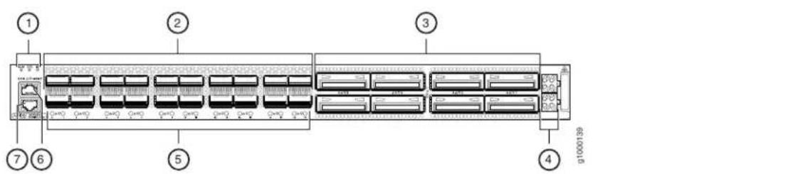
| 5-1- Network port LEDs (for the QSFP28 ports)System sta | |
| 6-2- Console portNetwork ports (QSFP28 ports) | |
| 7-3- Management portNetwork ports (CFP2-DCO ports) | |
| 4-Network port LEDs (for the CFP2-DCO ports) |
Table 7 on page 27 describes the chassis status LEDs on an ACX6360, their colors and states, and the status they indicate.
Table 7: Chassis Status LEDs on an ACX6360 Device
| DescriptionStateColorName | ||
| The device is halted or there is no alarm.OffUnlitALM- | ||
| On steadilyRed | A major hardware fault has occurred, such as a temperature alarm or power failure, and the device has halted. Power off the device by setting the AC power source outlet to the OFF (O) position, or unplugging the AC power cords. Correct any voltage or site temperature issues, and allow the device to cool down. Power on the device and monitor the power supply and fan LEDs to help determine where the error is occurring. | |
| On steadilyAmber | A minor alarm has occurred, such as a software error. Power off the device by setting the AC power source outlet to the OFF (O) position, or unplugging the AC power cords. Power on the device and monitor the status LEDs to ensure that Junos OS boots properly. | |
| The device is powered off or halted.OffUnlitSYS-Syster | ||
| Junos OS is loaded on the device.On steadilyGreen | ||
| OffUnlitID-Identification | The beacon feature is not enabled on the device. This feature is enabled using the request chassis beacon command. | |
| BlinkingBlue | The beacon feature is enabled on the device. This feature is enabled using the request chassis beacon command. |
ACX6360 Management Port LEDs
There are two management ports on the ACX6360, Both ports are labeled MGMT. The RJ-45 management port is for 10/100/1000BASE-T connections and is located on the port panel. The small form-factor pluggable (SFP) management port is for 10/100/1000BASE-T and 1000BASE-X connections and is located on the FRU end of the device.
The RJ-45 port has separate LEDs for status and activity. The SFP port has a LED to indicate both link and activity. Figure 5 on page 28 shows the location of the LEDs.
Figure 5: Management Port LEDs on an ACX6360

Table 8 on page 28 describes the RJ-45 management port LEDs.
Table 8: ACX6360 RJ-45 Management Port LEDs
| DescriptionStateColorLED | |||
| No link is established, there is a fault, or the link is down.OffUnlitLin | |||
| A link is established, and there is link activity.Blinking or flickeringAmt | |||
| OffUnlitStatus | Either the port speed is 10 Mbps or the link is down. | ||
| Green | On steadily | The port speed is 1000 Mbps. |
Table 9 on page 28 describes the SFP management port LED.
Table 9: ACX6360 SFP Management Port LED
| LED | Color | State | Description |
| Link activity | Unlit | Off | No link is established, there is a fault, or the link is down. |
| Green | On steadily | A link is established, but there is no link activity. | |
| Blinking or flickering | A link is established, and there is link activity. |
ACX6360 Network Port LEDs
Each ACX6360 network port uses a single bicolored LED to indicate link status and activity. The circular LEDs for the QSFP28 ports are located underneath the ports. The triangular arrow next to the LED points either up or down indicating whether the LED is associated with the top or bottom port. The circular LEDs for the CFP2 ports are located to the right of the ports. Figure 6 on page 29 shows the location of the LEDs.
Figure 6: Network Port LEDs on an ACX6360

2-1— Network port LEDs (for the CFP2 ports)Network port
For the QSFP28 ports, the number next to the LED indicates the port number that the LED belongs to and the arrow next to the LED indicates if it is the top or bottom port.
Table 10 on page 29 describes the QSFP28 network port LEDs.
Table 10: ACX6360 QSFP28 Port LEDs
| DescriptionStateColor | ||
| OffUnlit | The port is administratively disabled, there is no power, the link is down, or a transceiver is not present. | |
| A link is established.On steadilyGreen | ||
| The beacon function was enabled on the port.Blinking | ||
| On steadilyAmber | When the port is configured to operate as four 10-Gigabit Ethernet interfaces, indicates that one or more interfaces (but not all four) are up. | |
| There are one or more errors on the connections.Blinking |
For the CFP2 ports, the number next to the LED indicates the port number that the LED belongs to.
Table 11 on page 29 describes the CFP2 network port LEDs.
Table 11: ACX6360 CFP2 Port LEDs
| DescriptionStateColor | ||
| Unlit | Off | The port is administratively disabled, there is no power, the link is down, or a transceiver is not present. |
| Green | On steadily | A link is established. |
| Blinking | The beacon function was enabled on the port. |
Related Documentation
ACX6360 System Overview on page 19
• ACX6360 Management Panel on page 30
• show chassis alarms
ACX6360 Management Panel
- ACX6360 Management Panel on page 30
ACX6360 Management Panel
The ACX6360 management panel is found on the Field Replaceable Unit (FRU) end of the device.
You manage the ACX6360 by using the Junos OS CLI, which is accessible through the console and out-of-band management ports on the management panel. In addition, the management panel has system status LEDs that alert you to minor or major alarms or other issues with the router, external clock synchronization ports, and a USB port to support software installation and recovery. See Figure 7 on page 30 for management panel details.
Figure 7: ACX6360 Management Panel
| 6-1- Power suppliesSFP PTP Ethernet (1000BASE-T) port (labeled PTP). The PTP port is not currently supported. It is reserved for future use. | |
| SFP management Ethernet port (labeled 7-2-Pulses-per-secondSMB connector (labeled MGMT). In the Junos OS CLI, this port is PPS) input and output. The PPS port is not currently supported. It is reserved for future use. | |
| RS-232 Time-of-day port (labeled TOD). 8-3- 10 MHz SubMiniature B (SMB) connector The TOD port is not currently supported. It (labeled 10M) input and output. The 10M port is not currently supported. It is reserved for future use. | |
| Electrostatic discharge (ESD) terminal | 9-4- Reset button. Press and hold 5 seconds to reset the hardware. |
| Fan modules | 10-5- USB port. |
Related Documentation
ACX6360 System Overview on page 19
- ACX6360 Port Panel on page 24
ACX6360 Cooling System
- ACX6360 Cooling System Description on page 31
- ACX6360 Fan Module LEDs on page 33
ACX6360 Cooling System Description
• Fan Modules on page 31
• Airflow Through the Chassis on page 32
Fan Modules
The cooling system in an ACX6360 device consists of fan modules and a single fan in each power supply. There are five fan modules in the ACX6360. The airflow direction on the ACX6360 is airflow out, air comes into the device through the vents in the port panel.
The fanmodules in the ACX6360 are hot-insertable and hot-removable field-replaceable units (FRUs). These fan modules are designed for the airflow out direction. The fan modules are installed in the fan module slots on the management panel of the device next to the power supplies. The ACX6360 has 5 fan modules numbered 0 through 4 from left to right. Each fan module slot has a fan icon next to it.
Figure 8 on page 31 shows the location of the fan modules on the device.
Figure 9 on page 31 shows an example of the fan module.
Figure 8: ACX6360 FRU Panel

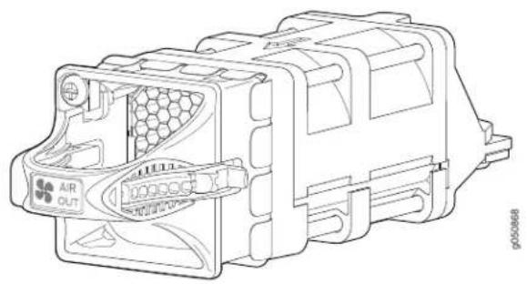
Figure 9 on page 31 shows the fan module for the ACX6360.
Figure 9: ACX6360 Fan Module
natural_image
Technical line drawing of an air vent connector housing (no text or symbols)You remove and replace a fan module from the FRU end of the chassis. The device continues to operate for a limited period of time (30 seconds) during the replacement of the fan module without thermal shutdown.

NOTE: All fan modules must be installed for optimal operation of the device.
Table 12 on page 32 lists the fan module product SKU.
Table 12: ACX6360 Fan Modules
| Label on the Fan ModuleFan Module | Power SuppliesDirection o |
AIR OUTJNP-FAN-1RU
Port-to-FRU, that is, air comes in through you must install only power vents on the end with ports; air exhaust supplies that have AIR OUT out the end with the fans (also known labels in devices in which the front-to-back airflow). fan modules have AIR OUT labels.
Airflow Through the Chassis
In the ACX6360 cooling system, cool air enters through the vents in the port panel and hot air exhausts through the FRU panel. This type of airflow is known as airflow out or port-to-FRU airflow. When the chassis is installed, it must be positioned so that the FRUs are next to the hot aisle. Figure 10 on page 32 shows the airflow through the chassis.
Figure 10: Airflow Through the ACX6360 Chassis (Port-to-FRU)

flowchart
graph TD
    A["Ports"] --> B["Port 1"]
    A --> C["Port 2"]
    A --> D["Port 3"]
    A --> E["Port 4"]
    A --> F["Port 5"]
    A --> G["Port 6"]
    A --> H["Port 7"]
    A --> I["Port 8"]
    A --> J["Port 9"]
    A --> K["Port 10"]
    A --> L["Port 11"]
    A --> M["Port 12"]
    A --> N["Port 13"]
    A --> O["Port 14"]
    A --> P["Port 15"]
    A --> Q["Port 16"]
    A --> R["Port 17"]
    A --> S["Port 18"]
    A --> T["Port 19"]
    A --> U["Port 20"]
    A --> V["Port 21"]
    A --> W["Port 22"]
    A --> X["Port 23"]
    A --> Y["Port 24"]
    A --> Z["Port 25"]
    A --> AA["Port 26"]
    A --> AB["Port 27"]
    A --> AC["Port 28"]
    A --> AD["Port 29"]
    A --> AE["Port 30"]
    A --> AF["Port 31"]
    A --> AG["Port 32"]
    A --> AH["Port 33"]
    A --> AI["Port 34"]
    A --> AJ["Port 35"]
    A --> AK["Port 36"]
    A --> AL["Port 37"]
    A --> AM["Port 38"]
    A --> AN["Port 39"]
    A --> AO["Port 40"]
    A --> AP["Port 41"]
    A --> AQ["Port 42"]
    A --> AR["Port 43"]
    A --> AS["Port 44"]
    A --> AT["Port 45"]
    A --> AU["Port 46"]
    A --> AV["Port 47"]
    A --> AW["Port 48"]
    A --> AX["Port 49"]
    A --> AY["Port 50"]

NOTE: Under normal operating conditions, the fan modules operate at a moderatespeed. Temperature sensors in the chassismonitorthetemperature within the chassis. The system raises an alarm if a fan module fails or if the ambient temperature inside the chassis rises above the acceptable range. If the temperature inside the chassis rises above the threshold temperature, the system shuts down automatically.
ACX6360 Fan Module LEDs
You can check the status of fan modules through the show system alarms command or by looking at the LEDs next to each fan module.
Figure 11 on page 33 shows the location of the LED next to the fan module.
Figure 11: Fan Module LEDs on an ACX6360

flowchart
graph LR
    A["Component 1"] --> B["Component 2"]
    B --> C["Component 3"]
    C --> D["Component 4"]
    D --> E["Component 5"]
    E --> F["Component 6"]
    F --> G["Component 7"]
    G --> H["Component 8"]
    H --> I["Component 9"]
    I --> J["Component 10"]
    style A fill:#f9f,stroke:#333
    style J fill:#f9f,stroke:#333
1— Fan LED
Use Table 13 on page 33 describes the function of the fan module LED.
Table 13: ACX6360 Fan Module LED
| DescriptionLED StateLED Color | ||
| On steadilyGreen | The fan module is operating normally. The system has verified that the module is engaged, that the airflow is in the correct direction, and that the fan is operating correctly. | |
| BlinkingAmber | An error has been detected in the fan module. Replace the fan module as soon as possible. Either the fan has failed or it is seated incorrectly. To maintain proper airflow through the chassis, leave the fan module installed in the chassis until you are ready to replace it. |
Related ACX6360 System Overview on page 19. Documentation - ACX6360 Power System on page 33
ACX6360 Power System
• ACX6360 AC Power Supply Description on page 34
• ACX6360 AC Power Supply LEDs on page 35
• ACX6360 DC Power Supply Description on page 35
• ACX6360 DC Power Supply LEDs on page 37
• ACX6360 AC Power Specifications on page 37
• ACX6360 AC Power Cord Specifications on page 38
• ACX6360 DC Power Specifications on page 39
• ACX6360 DC Power Cable Specifications on page 40
ACX6360 AC Power Supply Description
The two power supplies in an ACX6360 are hot-removable and hot-insertable field-replaceable units (FRUs). The power supplies are installed in the device at the factory. You can install replacement power supplies from the management panel without powering off the device or disrupting the devices functions.
The AC power supply is 850 W. Figure 12 on page 34 shows the location of the power supplies on the FRU end of the device. Figure 13 on page 34 shows an example of the AC power supply. The ACX6360 has two power supplies.

CAUTION: Do not mix AC and DC power supplies in the same chassis.
Figure 12: ACX6360 FRU Panel

| 3-1- Power supplies (2)Management pane | |
| 2-Fan modules (5) |
Figure 13: AC Power Supply in an ACX6360

| 3-1- AC application inletHandle | |
| 2-Cord retainer | 4-Latch lever |
When the ACX6360 has both power supplies installed and connected to power, the device has full power redundancy. If a power supply fails or is removed, another power supply balances the electrical load without interruption.

CAUTION: To avoid electrical injury, carefully follow instructions in "Connecting the ACX6360 to Power" on page69, "Maintaining the ACX6360 Power Supplies" on page 100.
ACX6360 AC Power Supply LEDs
Figure 14 on page 35 shows the location of the LED on the power supply.
Figure 14: AC Power Supply LED on an ACX6360

Table 14 on page 35 describes the LEDs on the AC power supplies.
Table 14: ACX6360 AC Power Supply LEDs
| DescriptionStateColorLED | ||
| OffUnlitAC | The power supply is disconnected from power, or power is not coming into the power supply. | |
| Power is coming into the power correctly.On steadilyGreen | ||
| OffUnlitDC | The power supply is disconnected from power, or the power supply is not sending out power correctly. | |
| The power supply is sending out power correctly.On steadilyGreen | ||
| On steadilyAmber! | (Rule)ror has been detected in the power supply. Replace the power supply as soon as possible. To maintain proper airflow through the chassis, leave the power supply installed in the chassis until you are ready to replace it. |

NOTE: If the AC LED and the DC LED are unlit, either the AC power cord is not installed properly or the power supply fuse has failed. If the AC LED is lit and the DC LED is unlit, the AC power supply is installed properly, but the power supply has an internal failure.
ACX6360 DC Power Supply Description
The power supplies in ACX6360 devices (see Figure 15 on page 36) are hot-removable and hot-insertable field-replaceable units (FRUs) that you can install in an ACX6360 device without powering off the device or disrupting the routing functions.
The DC power supply is 850 W with dual feeds for power resiliency.
Figure 15: ACX6360 DC Power Supply
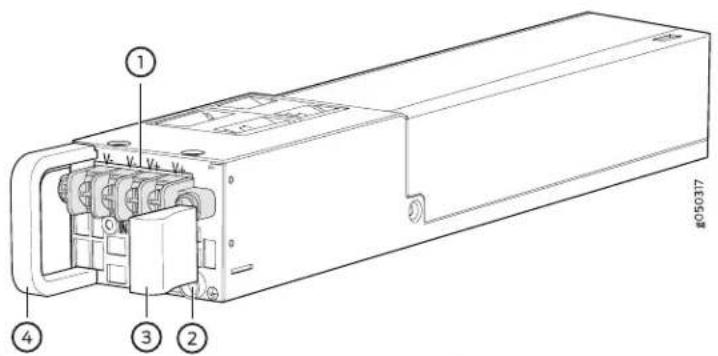
| 3-1- Latch leverTerminal block | |
| 4-2- HandleESD grounding point |

NOTE: The DC power supply has four terminals labeled V-, V-, V+, and V+ (see Figure 16 on page 36 for connecting DC power source cables labeled positive (+) and negative (-).
Figure 16: ACX6360 DC Power Supply Faceplate
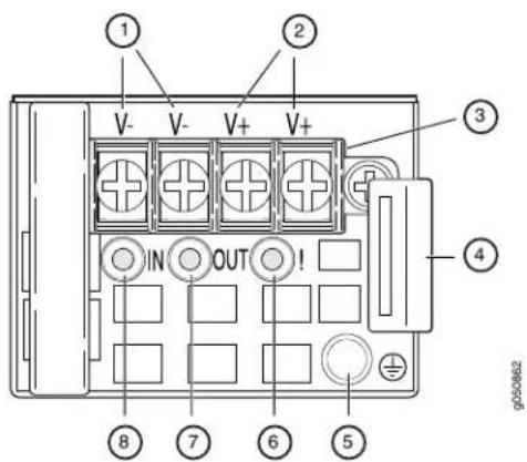
| 5-1-- ESD grounding point- Shunt negative input termin | |
| 6-2-- Fault LED- Shunt positive input terminals (+RTN) | |
| - Terminal block | 7-3-- Output LED |
| - Latch lever | 8-4-- Input LED |

CAUTION: To avoid electrical injury, carefully follow instructions in "Connecting the ACX6360 to Power" on page 69, "Maintaining the ACX6360 Power Supplies" on page 100.
See Also
ACX6360 DC Power Supply LEDs
Figure 16 on page 36 shows the location of the LED on the DC power supply.

CAUTION: The V+ terminals are shunted internally together, as are the V-terminals. The same polarity terminal can be wired together from the same source to provide an additional current path in a higher power chassis. Do not connect the terminals to different sources.
Table 15 on page 37 describes the LEDs on the DC power supplies.
Table 15: ACX6360 DC Power Supply LEDs
| DescriptionStateColorName | ||
| OffUnlitIN | The power supply is disconnected from power or power is not coming into the power supply. | |
| Power is coming into the power supply.On steadilyGreen | ||
| OffUnlitOUT | The power supply is disconnected from power or the power supply is not sending out power correctly. | |
| Power is sending out power correctly.On steadilyGreen | ||
| On steadilyAmber! (Fault) | Error has been detected in the power supply. Replace the power supply as soon as possible. To maintain proper airflow through the chassis, leave the power supply installed in the chassis until you are ready to replace it. |
ACX6360 AC Power Specifications
Table 16 on page 37 describes the AC power specifications for ACX6360 AC power supplies.
Table 16: AC Power Specifications for an ACX6360 Device
| SpecificationItem | |
| AC input voltage | Operating range:• 120 / 240 VAC |
| AC input line frequency | 50–60 Hz |
| AC input current rating | 12 A |
| Typical power consumption | 790 WNOTE: Power consumption numbers are preliminary. |
| Maximum power consumption | 820 WNOTE: Power consumption numbers are preliminary. |
ACX6360 AC Power Cord Specifications
Detachable AC power cords are shipped with the chassis, if you include them as part of your order. The coupler is type C13 as described by International Electrotechnical Commission (IEC) standard 60320. The plug at the male end of the power cord fits into the power source outlet that is standard for your geographical location.

NOTE: In North America, AC power cords must not exceed 14.75 feet (approximately 4.5 meters) in length, to comply with National Electrical Code (NEC) Sections 400-8 (NFPA 75, 5-2.2) and 210-52, and Canadian Electrical Code (CEC) Section 4-010(3).
Table 17 on page 39 lists AC power cord specifications provided for each country or region.
Table 17: AC Power Cord Specifications
| Electrical SpecificationsCountry/Region | Shipped Juniper Model NumberPlug | Spare Juniper Model Standards | Graphic | ||
| CBL-EX-PWR-C13-AUCG_CBL-C13-06-AUAS/NZ 3109 | |||||
| CBL-EX-PWR-C13-CHCG_CBL-C13-06-CHGB 1002-199 | |||||
| Italy, Switzerland,and UnitedKingdom) | CBL-EX-PWR-C13-EUCG_CBL-C13-06-EUCEE (7) VII2 | ||||
| Italy | 250 VAC, 10 A, 50 Hz | CEI 23-16/VII | CG_CBL-C13-06-IT | CBL-EX-PWR-C13-IT | |
| Japan | 125 VAC, 12 A, 50 Hz or 60 Hz | JIS C8303 | CG_CBL-C13-06-JP | CBL-EX-PWR-C13-JP | |
| North America | 250 VAC, 15 A, 60 Hz250 VAC, 15 A, 60 Hz | 49-92HzNEMA L6-15NEMA 6-15 | CG_CBL-C13-06-USCAN | NETSAX-RWRC-C13-USCBL-PW-C13-250-USCBL-PWR-C13-250-US | |
| South Korea | 250 VAC, 10 A, 60 Hz250 VAC, 13 A, 60 Hz | CBL-EX-PWR-C13-KRCG_CBL-C13-06-KRKSC 8305; | |||
| 250 VAC, 10 A, 50 Hz | SW101915V1991;EN 60320 C13 | CG_CBL-C13-06-SZ | CBL-EX-PWR-C13-SZ | ||
| United Kingdom | 250 VAC, 10 A, 50 Hz | BS 1363/A | CG_CBL-C13-06-UK | CBL-EX-PWR-C13-UK | |
ACX6360 DC Power Specifications
Table 18 on page 39 describes the DC power specifications for ACX6360 DC power supplies.
Table 18: DC Power Specifications for an ACX6360
| Item | Specifications |
| DC input voltage | Rated operating voltage: -48 VDC to -60 VDCOperating voltage range: -40 VDC through -72 VDC |
| DC input current rating | 21 A |
| Typical power consumption | 790 WNOTE: Power consumption numbers are preliminary. |
| SpecificationsItem | |
| Maximum power consumption | 820 WNOTE: Power consumption numbers are preliminary. |
ACX6360 DC Power Cable Specifications
ACX6360 DC power supplies require a D-Sub 3W3-type connector. The three pins on the connector provide -48 VDC input (−), return (+), and ground connections to the power supply.

NOTE: The optional right-angle DC power cables, CBL-JNP-PWR-DSUB2 and CBL-JNP-PWR-DSUB3, do not include a ground connection wire.
Regardless which DC power cable you use, you must connect the ACX6360 to earth ground before you connect it to to power, using the procedure described in "Connecting the ACX6360 Grounding Cable" on page 70.
DC power cables, each approximately 13.1 ft (4 m) long, are supplied with the ACX6360. The provided cables include the three-pin connector on one end and insulated wires at the opposite end, for connection to the site's DC power distribution system.
Table 19 on page 40 lists the specifications for the ACX6360 DC power cables.
Table 19: ACX6360 DC Power Cable Specifications
| Wire SizelInsulation ColorWire Fun | ||
| (straight cable) | 8 AWG (8.4 mm2), 90° CBlue-48 VDC input (-)CBL | |
| 8 AWG (8.4 mm2), 90° CBlackReturn (+) | ||
| 8 AWG (8.4 mm2), 90° CGreen and yellowGround | ||
| (right-angle cable) | 8 AWG (8.4 mm2), 90° CBlue-48 VDC input (-)CBL | |
| 8 AWG (8.4 mm2), 90° CBlackReturn (+) | ||
| (FT4 vertical-flame rated, right-angle cable) | 8 AWG (8.4 mm2), 90° CGray-48 VDC input (-)CBL | |
| 8 AWG (8.4 mm2), 90° CGrayReturn (+) | ||

WARNING: For field-wiring connections, use copper conductors only.

WARNING: Power cables must not block access to ACX6360 components or drape where people could trip over them.

CAUTION: You must ensure that power connections maintain the proper polarity. The power source cables might be labeled (+) and (−) to indicate their polarity. There is no standard color coding for DC power cables. The color coding used by the external DC power source at your site might be different from the color coding for the leads on the DC power cable provided with the chassis.
See Also
Related ACX6360 Installation Overview on page 63 Documentation Maintaining the ACX6360 Power Supplies on page 100
CHAPTER 2
Site Planning, Preparation, and Specifications
• ACX6360 Site Preparation Checklist on page 43
- ACX6360 Site Guidelines and Requirements on page 44
• ACX6360 Network Cable and Transceiver Planning on page 50
- ACX6360 Management Cable Specifications and Pinouts on page 60
ACX6360 Site Preparation Checklist
The checklist in Table 20 on page 43 summarizes the tasks you need to perform when preparing a site for an ACX6360 installation.
Table 20: Site Preparation Checklist
| DatePerformed byFor Mor | ||
| Environment | ||
| Verify that environmental factors such as temperature and humidity do not exceed router tolerances. | “ACX6360 Environmental Requirements and Specifications” on page 45 | |
| Power | ||
| Measure the distance between external power sources and the router installation site. | ||
| Calculate the power consumption and requirements. | ACX6360 AC Power Specifications on page 37ACX6360 AC Power Cord Specifications on page 38 | |
| Rack or Cabinet | ||
| Verify that your rack or cabinet meets the minimum requirements for the installation of the router. | ACX6360 Rack Requirements on page 48ACX6360 Cabinet Requirements on page 49 | |
| Figure 17 on page 47Plan rack or cabinet location,including required space clearances. | ||
| Secure the rack or cabinet tothe floor and building structure. | ||
| Cables | ||
| Acquire cables and connectors: | ACX6360 Network Cable and Transceiver Planning on page 50 | |
| • Determine the number of cables needed based on your plannedconfiguration. | ||
| • Review the maximum distance allowed for each cable. Choose the length of cable based on the distance between the hardware components being connected. | ||
| Plan the cable routing and management. | ||
| Related Documentation | ACX6360 Installation Safety Guidelines on page 64•Installation Instructions Warning on page 136•Chassis and Component Lifting Guidelines on page 137•Restricted Access Warning on page 137•Ramp Warning on page 138•Rack-Mounting and Cabinet-Mounting Warnings on page 139•Grounded Equipment Warning on page 143 |
ACX6360 Site Guidelines and Requirements
• ACX6360 Environmental Requirements and Specifications on page 45
- General Site Guidelines on page 46
- ACX6360 Chassis Grounding Cable and Lug Specifications on page 46
- ACX6360 Clearance Requirements for Airflow and Hardware Maintenance on page 47
• ACX6360 Physical Specifications on page 47
- Site Electrical Wiring Guidelines on page 48
• ACX6360 Rack Requirements on page 48
• ACX6360 Cabinet Requirements on page 49
ACX6360 Environmental Requirements and Specifications
The ACX6360 must be installed in a rack or cabinet. It must be housed in a dry, clean, well-ventilated, and temperature-controlled environment.
Follow these environmental guidelines:
- The site must be as dust-free as possible, because dust can clog air intake vents and filters, reducing the efficiency of the ACX6360 cooling system.
- Maintain ambient airflow for normal ACX6360 operation. If the airflow is blocked or restricted, or if the intake air is too warm, the chassis might overheat, leading to the ACX6360 temperature monitor shutting down the router to protect the hardware components.
Table 21 on page 45 provides the required environmental conditions for normal ACX6360 operation.
Table 21: ACX6360 Environmental Tolerances
| ToleranceDescription | |
| No performance degradation up to 13,000 feet (3962.4 meters).Altitude | |
| Relative humidity | Normal operation ensured in relative humidity range of 5% through 90%, noncondensing.Short-term operation ensured in relative humidity range of 5% through 93%, but not to exceed 0.026 kg water/kg of dry air.NOTE: As defined in NEBS GR-63-CORE, Issue 3, short-term events can be up to 96 hours in duration but not more than 15 days per year. |
| Temperature | Normal operation ensured in temperature range of 32^ F through 104^ F ( 0^ C through 40^ C).Nonoperating storage temperature in shipping container: -40^ F through 158^ F ( -40^ C through 70^ C). |
| Designed to comply with Zone 4 earthquake requirements per NEBS GR-63-CORE, Issue 3.Seismic |

NOTE: Install the ACX6360 only in restricted areas, such as dedicated equipment rooms and equipment closets, in accordance with Articles 110-16, 110-17, and 110-18 of the National Electrical Code, ANSI/NFPA 70.
General Site Guidelines
Efficient device operation requires proper site planning and maintenance and proper layout of the equipment, rack or cabinet (if used), and wiring closet.
To plan and create an acceptable operating environment for your device and prevent environmentally caused equipment failures:
- Keep the area around the chassis free from dust and conductive material, such as metal flakes.
- Follow prescribed airflow guidelines to ensure that the cooling system functions properly and that exhaust from other equipment does not blow into the intake vents of the device.
- Follow the prescribed electrostatic discharge (ESD) prevention procedures to prevent damaging the equipment. Static discharge can cause components to fail completely or intermittently over time.
- Install the device in a secure area, so that only authorized personnel can access the device.
ACX6360 Chassis Grounding Cable and Lug Specifications
For installations that require a separate grounding conductor to the chassis, the ACX6360 must be adequately grounded before power is connected to ensure proper operation and to meet safety and electromagnetic interference (EMI) requirements. To ground an ACX6360, connect a grounding cable to earth ground and then attach it to the chassis grounding points.

WARNING: The device is a pluggable type A equipment installed in a restricted-access location. It has a separate protective earthing terminal provided on the chassis in addition to the grounding pin of the power supply cord. This separate protective earthing terminal must be permanently connected to earth ground for installations that require a separate grounding conductor to the chassis.

WARNING: To comply with GR-1089 requirements, all intrabuilding copper cabling used for SFP+, QSFP+, and QSFP28 ports must be shielded and grounded at both ends.

CAUTION: Before device installation begins, a licensed electrician must attach a cable lug to the grounding cables that you supply. See “Connecting the ACX6360 Grounding Cable” on page 70. A cable with an incorrectly attached lug can damage the ACX6360.
Before connecting the ACX6360 to earth ground, review the following information:
- The grounding lug required is a Panduit LCD10-10A-L or equivalent (not provided). The grounding lug accommodates 14–10 AWG (2–5.3 mm ^2 ) stranded wire.
- The grounding cable that you provide for an ACX6360 must be the same size or heavier than the input wire of each power supply. Minimum recommendations are 14 AWG (2 mm ^2 ) stranded wire, 60° C wire, or as permitted by local code.
ACX6360 Clearance Requirements for Airflow and Hardware Maintenance
When planning the site for an ACX6360 installation, you must allow sufficient clearance around the installed chassis (see Figure 17 on page 47).
Figure 17: Clearance Requirements for Airflow and Hardware Maintenance for an ACX6360

Follow these guidelines:
- For the cooling system to function properly, the airflow around the chassis must be unrestricted. See "ACX6360 Cooling System" on page 30 for more information about the airflow through the chassis.
- If you are mounting an ACX6360 in a rack with other equipment, ensure that the exhaust from other equipment does not blow into the intake vents of the chassis.
- You must leave at least 24 in. (61 cm) both in front of and behind the ACX6360 for servicepersonnel toremove and install hardware components, you must leave adequate space at the front and back of the ACX6360. NEBS GR-63 recommends that you allow at least 30 in. (76.2 cm) in front of the rack or cabinet and 24 in. (61 cm) behind the rack.
ACX6360 Physical Specifications
Table 22 on page 48 lists the physical specifications for the ACX6360 chassis.
Table 22: Physical Specifications for the ACX6360
| DepthWidthHeightV | ||||
| ACX6360-20C | installed: 30.4 lbs (13.8 kg) | 25.92 in. (65.83 cm)17.36 in. (44.09 | ||
Site Electrical Wiring Guidelines
Table 23 on page 48 describes the factors you must consider while planning the electrical wiring at your site.

WARNING: You must provide a properly grounded and shielded environment and use electrical surge-suppression devices.
Table 23: Site Electrical Wiring Guidelines
| GuidelinesSite Wiring Factor | |
| Signaling limitations | If your site experiences any of the following problems, consult experts in electrical surge suppression and shielding:Improperly installed wires cause radio frequency interference (RFI).Damage from lightning strikes occurs when wires exceed recommended distances or pass between buildings.Electromagnetic pulses (EMPs) caused by lightning damage unshielded conductors and electronic devices. |
| Radio frequency interference | To reduce or eliminate RFI from your site wiring, do the following:Use a twisted-pair cable with a good distribution of grounding conductors.If you must exceed the recommended distances, use a high-quality twisted-pair cable with one ground conductor for each data signal when applicable. |
| Electromagnetic compatibility | If your site is susceptible to problems with electromagnetic compatibility (EMC), particularly from lightning or radio transmitters, seek expert advice.Some of the problems caused by strong sources of electromagnetic interference (EMI) are:Destruction of the signal drivers and receivers in the deviceElectrical hazards as a result of power surges conducted over the lines into the equipment |
ACX6360 Rack Requirements
The ACX6360 chassis is designed to be installed in four-post racks.
Rack requirements consist of:
- Rack type
- Mounting bracket hole spacing
- Rack size and strength
Table 24 on page 49 provides the rack requirements and specifications for the ACX6360.
Table 24: Rack Requirements for the ACX6360
| GuidelinesRack Requirement | |
| Rack type: four-post | Use a four-post rack that provides bracket holes or hole patterns spaced at 1-U (1.75 in. or 4.45 cm) increments and that meets the size and strength requirements to support the weight.A U is the standard rack unit defined in Cabinets, Racks, Panels, and Associated Equipment (document number EIA-310-D) published by the Electronics Components Industry Association (http://www.ecianow.org/). |
| Mounting bracket hole spacing | The holes in the mounting brackets are spaced at 1 U (1.75 in. or 4.45 cm), so that the ACX6360 can be mounted in any rack that provides holes spaced at that distance. |
| Rack size and strength | · Ensure that the rack complies with the standards for a 19-in. rack as defined in Cabinets, Racks, Panels, and Associated Equipment (document number EIA-310-D) published by the Electronics Components Industry Association (http://www.ecianow.org/).· Use a 600-mm rack as defined in the four-part Equipment Engineering (EE); European telecommunications standard for equipment practice (document numbers ETS 300 119-1 through 119-4) published by the European Telecommunications Standards Institute (http://www.etsi.org).The horizontal spacing between the rails in a rack that complies with this standard is usually wider than the router's mounting brackets, which measure 19 in. (48.26 cm) from outer edge to outer edge. Use approved wing devices to narrow the opening between the rails as required.· Ensure that the rack rails are spaced widely enough to accommodate the ACX6360 chassis' external dimensions. The outer edges of the front-mounting rails extend the width to 19 in. (48.26 cm).· Ensure that the front and rear rack rails are spaced between 23.6 in. (60 cm) and 36 in. (91.4 cm) front-to-back.· Ensure that the rack is strong enough to support the weight of the device.· Ensure that the spacing of rails and adjacent racks allows for proper clearance around the ACX6360 and rack. |
| Rack connection to building structure | · Secure the rack to the building structure.· If earthquakes are a possibility in your geographical area, secure the rack to the floor.· Secure the rack to the ceiling brackets as well as wall or floor brackets for maximum stability. |
ACX6360 Cabinet Requirements
You can mount the ACX6360 in an enclosure or cabinet that contains a four-post 19-in. open rack as defined in Cabinets, Racks, Panels, and Associated Equipment (document number EIA-310-D) published by the Electronics Industry Association.
Cabinet requirements consist of:
- Cabinet size and clearance
• Cabinet airflow requirements
Table 25 on page 50 provides the cabinet requirements and specifications for the ACX6360.
Table 25: Cabinet Requirements for the ACX6360
| GuidelinesCabinet Requirement | |
| Cabinet size and clearance | The minimum cabinet size for accommodating an ACX6360 device is 36 in. (91.4 cm) deep. Large cabinets improve airflow and reduce the chance of overheating. |
| Cabinet airflow requirements | When you mount the device in a cabinet, ensure that ventilation through the cabinet is sufficient to prevent overheating.Ensure that the cool air supply you provide through the cabinet adequately dissipates the thermal output of the device.Ensure that the cabinet allows the chassis hot exhaust air to exit the cabinet without recirculating into the device. An open cabinet (without a top or doors) that employs hot air exhaust extraction from the top allows the best airflow through the chassis. If the cabinet contains a top or doors, perforations in these elements assist with removing the hot air exhaust.The ACX6360 fans exhaust hot air through the vents on the fans and power supplies. Install the device in the cabinet in a way that maximizes the open space on the FRU side of the chassis. This maximizes the clearance for critical airflow.Route and dress all cables to minimize the blockage of airflow to and from the chassis.Ensure that the spacing of rails and adjacent cabinets allows for the proper clearance around the device and cabinet. |
Related Documentation
ACX6360 Site Preparation Checklist on page 43.
•General Safety Guidelines and Warnings on page 132
•General Electrical Safety Guidelines and Warnings on page 151
•Prevention of Electrostatic Discharge Damage on page 153
ACX6360 Network Cable and Transceiver Planning
• Determining Transceiver Support for the ACX6360 on page 50
- Cable and Connector Specifications for the ACX6360 on page 51
• Understanding Fiber-Optic Cable Signal Loss, Attenuation, and Dispersion on page 56
• Calculating Power Budget and Power Margin for Fiber-Optic Cables on page 57
Determining Transceiver Support for the ACX6360
The ACX6360 has 28 network ports. The 20 QSFP28 network ports on the port panel support QSFP+ and QSFP28 transceivers, direct-attach copper (DAC) cables, active optical cables (AOC), and DAC breakout cables (DACBO). You can configure each of the 20 ports as 10-Gigabit Ethernet ports, 40-Gigabit Ethernet ports, or 100-Gigabit Ethernet ports.
The8 CFP2 network ports on theport panel supportCFP2 transceivers. You can configure each of the 8 CFP2 ports as 100-Gigabit Ethernet ports or 200-Gigabit Ethernet ports.
See "ACX6360 Port Panel" on page 24 for more information about the network ports.
You can find information about the pluggable transceivers supported on your Juniper Networks device by using the Hardware Compatibility Tool. In addition to transceiver and connector type, the optical and cable characteristics—where applicable—are documented for each transceiver. The Hardware Compatibility Tool enables you to search by product, displaying all the transceivers supported on that device, or category, by interface speed or type. The list of supported transceivers for the ACX6360 is located at https://pathfinder.juniper.net/hct/product/#prd=ACX6360.

CAUTION: If you face a problem running a Juniper Networks device that uses a third-partyopticorbable, the Juniper Networks Technical Assistance Center (JTAC) can help you diagnose the source of the problem. Your JTAC engineer might recommend that you checkthethird-partyopticor cable and potentially replace it with an equivalent Juniper Networks optic or cable that is qualified for the device.
Cable and Connector Specifications for the ACX6360
The transceivers that are supported on MX Series and PTX Series devices use fiber-optic cables and connectors. The type of connector and the type of fiber depends on the transceiver type.
You can determine the type of cable and connector required for your specific transceiver by using the Hardware Compatibility Tool.

CAUTION: To maintain agency approvals, use only a properly constructed, shielded cable.

NOTE: The terms multifiber push-on (MPO) and multifiber termination push-on (MTP) describe the same connector type. The rest of this topic uses MPO to mean MPO or MTP.
• 12-Fiber MPO Connectors on page 51
• 24-Fiber MPO Connectors on page 55
• LC Duplex Connectors on page 56
12-Fiber MPO Connectors
There are two types of cables used with 12-fiber MPO connectors on Juniper Networks devices—patch cables with MPO connectors on both ends, and breakout cables with an MPO connector on one end and four LC duplexconnectors on the opposite end. Depending on the application, the cables might use single-mode fiber (SMF) or multimode fiber (MMF). Juniper Networks sells cables that meet the supported transceiver requirements, but it is not required to purchase cables from Juniper Networks.
Ensure that you order cables with the correct polarity. Vendors refer to these crossover cables as key up to key up, latch up to latch up, Type B, or Method B. If you are using patch panels between two transceivers, ensure that the proper polarity is maintained through the cable plant.
Also, ensure that the fiber end in the connector is finished correctly. Physical contact (PC) refers to fiber that has been polished flat. Angled physical contact (APC) refers to fiber that has been polished at an angle. Ultra physical contact (UPC) refers to fiber that has been polished flat, to a finer finish. The required fiber end is listed with the connector type in the Hardware Compatibility Tool.
12-Fiber Ribbon Patch Cables with MPO Connectors
You can use 12-fiber ribbon patch cables with female MPO connectors to connect two transceivers of the same type—for example, 40GBASE-SR4-to-40GBASESR4 or 100GBASE-SR4-to-100GBASE-SR4. You can also connect 4x10GBASE-LR or 4x10GBASE-SR transceivers by using patch cables—for example,
4x10GBASE-LR-to-4x10GBASE-LR or 4x10GBASE-SR-to-4x10GBASE-SR—instead of breaking the signal out into four separate signals.
Table 26 on page 52 describes the signals on each fiber. Table 27 on page 53 shows the pin-to-pin connections for proper polarity.
Table 26: Cable Signals for 12-Fiber Ribbon Patch Cables
| SignalFiber | |
| Tx0 (Transmit)1 | |
| Tx1 (Transmit)2 | |
| Tx2 (Transmit)3 | |
| Tx3 (Transmit)4 | |
| Unused5 | |
| Unused6 | |
| Unused7 | |
| Unused8 | |
| Rx3 (Receive)9 | |
| Rx2 (Receive)10 | |
| Rx1 (Receive)11 | |
| Rx0 (Receive)12 |
Table 27: Cable Pinouts for 12-Fiber Ribbon Patch Cables
| MPO PinMPO Pin | |
| 1 | 12 |
| 2 | 11 |
| 3 | 10 |
| 4 | 9 |
| 5 | 8 |
| 6 | 7 |
| 7 | 6 |
| 8 | 5 |
| 9 | 4 |
| 10 | 3 |
| 11 | 2 |
| 12 | 1 |
12-Fiber Ribbon Breakout Cables with MPO-to-LC Duplex Connectors
You can use 12-ribbon breakout cables with MPO-to-LC duplex connectors to connect a QSFP+ transceiver to four separate SFP+ transceivers—for example,
4x10GBASE-LR-to-10GBASE-LR or 4x10GBASE-SR-to-10GBASE-SR SFP+ transceivers.
The breakout cable is constructed out of a 12-fiber ribbon fiber-optic cable. The ribbon cable splits from a single cable with a female MPO connector on one end, into four cable pairs with four LC duplex connectors on the opposite end.
Table 28 on page 53 describes the way the fibers are connected between the MPO and LC duplex connectors. The cable signals are the same as those described in Table 26 on page 52.
Table 28: Cable Pinouts for 12-Fiber Ribbon Breakout Cables
| LC Duplex Connector PinMPO Connector Pin | |
| 1 | Tx on LC Duplex 1 |
| 2 | Tx on LC Duplex 2 |
| 3 | Tx on LC Duplex 3 |
| 4 | Tx on LC Duplex 4Unused5 |
| Unused6 | |
| Unused7 | |
| Unused8 | |
| Rx on LC Duplex 49 | |
| Rx on LC Duplex 310 | |
| Rx on LC Duplex 211 | |
| Rx on LC Duplex 112 |
12-Ribbon Patch and Breakout Cables Available from Juniper Networks
Juniper Networks sells 12-ribbon patch and breakout cables with MPO connectors that meet the requirements described above. It is not required top purchase cables from Juniper Networks. Table 29 on page 54 describes the available cables.
Table 29: 12-Ribbon Patch and Breakout Cables Available from Juniper Networks
| Cable Type | Fiber TypeConnector Type | Juniper Model NumberCable Length | |
| 12-ribbon patch | Female MPO/PC to female MPO/PC, key (OM3) up to key up | MTP12-FF-M1M1 mMMF | |
| MTP12-FF-M3M3 m | |||
| MTP12-FF-M5M5 m | |||
| 10 m | MTP12-FF-M10M | ||
| Female MPO/APC tomSMF female MPO/APC, key up to key up | MTP12-FF-S1M | ||
| MTP12-FF-S3M3 m | |||
| 5 m | MTP12-FF-S5M | ||
| 10 m | MTP12-FF-S10M | ||
| 12-ribbon breakout | Female MPO/PC, key up, to four LC/UPC (OM3) duplex | MTP-4LC-M1M1 mMMF | |
| MTP-4LC-M3M3 m | |||
| MTP-4LC-M5M5 m | |||
| MTP-4LC-M10M10 m | |||
| up, to four LC/UPC duplex | MTP-4LC-S1M1 mSMFFemale MPO/APC, key | ||
| MTP-4LC-S3M3 m | |||
| MTP-4LC-S5M5 m | |||
| MTP-4LC-S10M10 m |
24-Fiber MPO Connectors
You can use patch cables with 24-fiber MPO connectors to connect two supported transceivers of the same type—for example, 100GBASE-SR10-to-100GBASE-SR10.
Figure 18 on page 55 shows the 24-fiber MPO optical lane assignments.
Figure 18: 24-Fiber MPO Optical Lane Assignments
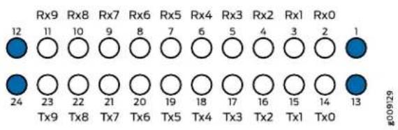

NOTE: Ensure that you order cables with the correct polarity. Vendors refer to these crossover cables as key up to key up, latch up to latch up, Type B, or Method B. If you are using patch panels between two transceivers, ensure that the proper polarity is maintained through the cable plant.
The MPO optical connector for the CFP2-100G-SR10-D3 is defined in Section 5.6 of the CFP2 Hardware Specification and Section 88.10.3 of IEEE STD 802.3-2012. These specifications include the following requirements:
- Recommended Option A in IEEE STD 802.3-2012 is required.
-
The transceiver receptacle is male. A patch cable with female connector is required to mate with the module.
-
Ferrule finish shall be flat polished interface that is compliant with IEC 61754-7.
- Alignment key is key up.
The optical interfacemust meet the requirement FT-1435-CORE in Generic Requirements for Multi-Fiber Optical Connectors. The module must pass wiggle test defined by IEC 62150-3.
LC Duplex Connectors
You can use patch cables with LC duplex connectors to connect two supported transceivers of the same type—for example, 40GBASE-LR4-to-40GBASE-LR4 or 100GBASE-LR4-to100GBASE-LR4. The patch cable is one fiber pair with two LC duplex connectors at opposite ends. LC duplex connectors are also used with 12-fiber ribbon breakout cables, as described in "12-Fiber Ribbon Breakout Cables with MPO-to-LC Duplex Connectors" on page 53.
Figure 19 on page 56 shows an LC duplex connector being installed in a transceiver.
Figure 19: LC Duplex Connector

Understanding Fiber-Optic Cable Signal Loss, Attenuation, and Dispersion
This topic describes signal loss, attenuation, and dispersion in fiber-optic cable.
• Signal Loss in Multimode and Single-Mode Fiber-Optic Cable on page 56
- Attenuation and Dispersion in Fiber-Optic Cable on page 57
Signal Loss in Multimode and Single-Mode Fiber-Optic Cable
Multimode fiber is large enough in diameter to allow rays of light to reflect internally (bounce off the walls of the fiber). Interfaces with multimode optics typically use LEDs as light sources. However, LEDs are not coherent sources. They spray varying wavelengths of light into the multimode fiber, which reflects the light at different angles. Light rays travel in jagged lines through a multimode fiber, causing signal dispersion. When light traveling in the fiber core radiates into the fiber cladding, higher-order mode loss results. Together these factors limit the transmission distance of multimode fiber compared with single-mode fiber.
Single-mode fiber is so small in diameter that rays of light can reflect internally through one layer only. Interfaces with single-mode optics use lasers as light sources. Lasers generate a single wavelength of light, which travels in a straight line through the
single-mode fiber. Compared with multimode fiber, single-mode fiber has higher bandwidth and can carry signals for longer distances.
Exceeding the maximum transmission distances can result in significant signal loss, which causes unreliable transmission.
Attenuation and Dispersion in Fiber-Optic Cable
Correct functioning of an optical data link depends on modulated light reaching the receiver with enough power to be demodulated correctly. Attenuation is the reduction in power of the light signal as it is transmitted. Attenuation is caused by passive media components, such as cables, cable splices, and connectors. Although attenuation is significantly lower for optical fiber than for other media, it still occurs in both multimode and single-mode transmission. An efficient optical data link must have enough light available to overcome attenuation.
Dispersion is the spreading of the signal over time. The following two types of dispersion can affect an optical data link:
- Chromatic dispersion—Spreading of the signal over time resulting from the different speeds of light rays.
- Modal dispersion—Spreading of the signal over time resulting from the different propagation modes in the fiber.
For multimode transmission, modal dispersion, rather than chromatic dispersion or attenuation, usually limits the maximum bit rate and link length. For single-mode transmission, modal dispersion is not a factor. However, at higher bit rates and over longer distances, chromatic dispersion rather than modal dispersion limits maximum link length.
An efficient optical data link must have enough light to exceed the minimum power that the receiver requires to operate within its specifications. In addition, the total dispersion must be less than the limits specified for the type of link in Telcordia Technologies document GR-253-CORE (Section 4.3) and International Telecommunications Union (ITU) document G.957.
When chromatic dispersion is at the maximum allowed, its effect can be considered as a power penalty in the power budget. The optical power budget must allow for the sum of component attenuation, power penalties (including those from dispersion), and a safety margin for unexpected losses.
Calculating Power Budget and Power Margin for Fiber-Optic Cables
Use the information in this topic and the specifications for your optical interface to calculate the power budget and power margin for fiber-optic cables.

TIP: You can use the Hardware Compatibility Tool to find information about the pluggable transceivers supported on your Juniper Networks device.
To calculate the power budget and power margin, perform the following tasks:
- Calculating Power Budget for Fiber-Optic Cable on page 58
- Calculating Power Margin for Fiber-Optic Cable on page 58
Calculating Power Budget for Fiber-Optic Cable
To ensure that fiber-optic connections have sufficient power for correct operation, you need to calculate the link's power budget, which is the maximum amount of power it can transmit. When you calculate the power budget, you use a worst-case analysis to provide a margin of error, even though all the parts of an actual system do not operate at the worst-case levels. To calculate the worst-case estimate of power _B budget (P you assume minimum transmitter power) (and minimum receiver sensitivity):(P
$$ P _ {B} = P _ {T} - P _ {R} $$
The following hypothetical power budget equation uses values measured in decibels (dB) and decibels referred to one milliwatt (dBm):
$$ P _ {B} = P _ {T} - P _ {R} $$
$$ P _ {B} = - 1 5 \mathrm{dBm} - (- 2 8 \mathrm{dBm}) $$
$$ P _ {B} = 1 3 \mathrm{dB} $$
Calculating Power Margin for Fiber-Optic Cable
After calculating a link's power budget, you can calculate the power margin(P represents the amount of power available after subtracting attenuation or link loss (LL) from the power budget) (PA worst-case estimate of assumes maximum LL:
$$ P _ {M} = P _ {B} - L L $$
P_M greater than zero indicates that the power budget is sufficient to operate the receiver.
Factors that can cause link loss include higher-order mode losses, modal and chromatic dispersion, connectors, splices, and fiber attenuation. Table 30 on page 58 lists an estimated amount of loss for the factors used in the following sample calculations. For information about the actual amount of signal loss caused by equipment and other factors, refer to vendor documentation.
Table 30: Estimated Values for Factors Causing Link Loss
| Estimated Link-Loss ValueLink-Loss Factor | |
| Higher-order mode losses | Single mode—NoneMultimode—0.5 dB |
| Modal and chromatic dispersion | Single mode—NoneMultimode—None, if product of bandwidth and distance is less than 500 MHz-km0.5 dBConnector |
| 0.5 dBSplice | |
| Fiber attenuation | Single mode—0.5 dB/kmMultimode—1 dB/km |
The following sample calculation for a 2-km-long multimode link with a power budget ( P_B ) of 13 dB uses the estimated values from Table 30 on page 58 to calculate link loss (LL) asthesumoffiberattenuation (2 km @ 1 dB/km, or 2 dB) and lossfor five connectors (0.5 dB per connector, or 2.5 dB) and two splices (0.5 dB per splice, or 1 dB) as well as higher-order mode losses (0.5 dB). The power margins (Calculated as follows:
$$ P _ {M} = P _ {B} - L L $$
$$ P _ {M} = 1 3 \mathrm{dB} - 2 \mathrm{km} (1 \mathrm{dB/km}) - 5 (0. 5 \mathrm{dB}) - 2 (0. 5 \mathrm{dB}) - 0. 5 \mathrm{dB} $$
$$ P _ {M} = 1 3 \mathrm{dB} - 2 \mathrm{dB} - 2. 5 \mathrm{dB} - 1 \mathrm{dB} - 0. 5 \mathrm{dB} $$
$$ P _ {M} = 7 \mathrm{dB} $$
The following sample calculation for an 8-km-long single-mode link with a power budget ( P_B ) of 13 dB uses the estimated values from Table 30 on page 58 to calculate link loss (LL) as the sum of fiber attenuation (8 km @ 0.5 dB/km, or 4 dB) and loss for seven connectors (0.5 dB per connector, or 3.5 dB). The power marginal calculated as follows:
$$ P _ {M} = P _ {B} - L L $$
$$ P _ {M} = 1 3 \mathrm{dB} - 8 \mathrm{km} (0. 5 \mathrm{dB/km}) - 7 (0. 5 \mathrm{dB}) $$
$$ P _ {M} = 1 3 \mathrm{dB} - 4 \mathrm{dB} - 3. 5 \mathrm{dB} $$
$$ P _ {M} = 5. 5 \mathrm{dB} $$
In both examples, the calculated power margin is greater than zero, indicating that the link has sufficient power for transmission and does not exceed the maximum receiver input power.
| Related Documentation | Determining Transceiver Support and Specifications. |
| ACX6360 Port Panel on page 24 | |
| ACX6360 System Overview on page 19 |
ACX6360 Management Cable Specifications and Pinouts
- Cable Specifications for Console and Management Connections for the ACX6360 on page 60
- Management Port Connector Pinouts for the ACX6360 on page 60
- Console Port Connector Pinouts for the ACX6360 on page 61
• USB Port Specifications for the ACX6360 on page 61
Cable Specifications for Console and Management Connections for the ACX6360
Table 31 on page 60 lists the specifications for the cables that connect the ACX6360 to a management device.

NOTE: All RJ-45 connectors must conform to the rules and regulations as described in the FCC specification 47 CFR Part 68.
Table 31: Cable Specifications for Console and Management Connections for the ACX6360
| Device ReceptacleMa | ||||
| Console (CON) port | RS-232 (EIA-232) serial cable | RJ-45 patch cable and RJ-45 to DB-9 adapter | RJ-457 feet (2.13 meters)One 7 | |
| Management (MGMT) port | Category 5 cable or equivalent suitable for 1000BASE-T operation | One 7-foot (2.13-meter)-long RJ-45 patch cable | (100 meters) | RJ-45328 feet |
Management Port Connector Pinouts for the ACX6360
The 10/100/1000BASE-T RJ-45 management port (labeled MGMT) uses an RJ-45 connector to connect to a management device for out-of-band management.
Table 32 on page 60 provides the pinout information of the RJ-45 management port connector. An RJ-45 cable is supplied with the ACX6360.
Table 32: RJ-45 Management Port Connector Pinouts for the ACX6360
| DescriptionSignalPin | ||
| 1 | TRP1+ | Transmit/receive data pair 1 |
| 2 | TRP1- | Transmit/receive data pair 1 |
| 3 | TRP2+ | Transmit/receive data pair 2 |
| 4 | TRP3+ | Transmit/receive data pair 3 |
Table 32: RJ-45 Management Port Connector Pinouts for the ACX6360 (continued)
| DescriptionSignalPin | |
| Transmit/receive data pair 3TRP3-5 | |
| Transmit/receive data pair 2TRP2-6 | |
| Transmit/receive data pair 4TRP4+7 | |
| Transmit/receive data pair 4TRP4-8 |
Console Port Connector Pinouts for the ACX6360
The console port (labeled CON) is an RS-232 serial interface that uses an RJ-45 connector to connect to a console management device. The default baud rate for the console port is 9600 baud.
Table 33 on page 61 provides the pinout information for the RJ-45 console connector. An RJ-45 cable and an RJ-45 to DB-9 adapter are supplied with the ACX6360.

NOTE: If your laptop or PC does not have a DB-9 male connector pin and you wanttoconnectyour laptop or PC directly toanACX6360,usea combination of the RJ-45 cable and RJ-45 to DB-9 adapter supplied with the router and a USB to DB-9 maleadapter. You mustprovide theUSBtDB-9 maleadapter.
Table 33: Console Port Connector Pinouts for the ACX6360
| DescriptionSignalPin | ||
| 1 | RTS Output | Request to send |
| 2 | DTR Output | Data terminal ready |
| 3 | TxD Output | Transmit data |
| 4 | Signal Ground | Signal ground |
| 5 | Signal Ground | Signal ground |
| 6 | RxD Input | Receive data |
| 7 | DCD Input | Data carrier detect |
| 8 | CTS Input | Clear to send |
USB Port Specifications for the ACX6360
USB flash drives used with the ACX6360 must support USB 2.0 or later.

CAUTION: Remove the USB flash drive before upgrading Junos OS or rebooting an ACX6360. Failure to do so could expose your router to unpredictable behavior.
Related Documentation
•ACX6360 Port Panel on page 24
- ACX6360 Management Panel on page 30
CHAPTER 3
Initial Installation and Configuration
• ACX6360 Installation Overview on page 63
- Unpacking and Mounting the ACX6360 on page 65
- Connecting the ACX6360 to Power on page 69
- Connecting the ACX6360 to External Devices on page 78
- Performing Software Configurations on the ACX6360 on page 80
• Transponder Mode on the ACX6360 on page 83
• Powering Off the ACX6360 on page 93
ACX6360 Installation Overview
• Overview of Installing the ACX6360 on page 63
• ACX6360 Installation Safety Guidelines on page 64
Overview of Installing the ACX6360
You can mount an ACX6360 flush with the front of a 19-in. four-post rack. Use the standard mounting brackets provided with the ACX6360 for this configuration.
Before you begin to install and connect an ACX6360, ensure that you have reviewed the information in "ACX6360 Installation Safety Guidelines" on page 64.
To install and connect an ACX6360:
-
Unpack the ACX6360 and verify the components received. See "Unpacking the ACX6360" on page 65.
-
Determine how the device is to be mounted. Mount the ACX6360 in a rack or cabinet. See "Mounting the ACX6360" on page 68.
-
For installations that require a separate grounding conductor to the chassis, follow the instructions in "Connecting the ACX6360 Grounding Cable" on page 70.
-
Connect the ACX6360 to a management console for initial configuration. See "Connecting the ACX6360 to a Management Console" on page 79.
-
Connect the ACX6360 to power. Depending on your configuration, follow the instructions in "Connecting AC Power to the ACX6360" on page 71 or "Connecting DC Power to the ACX6360" on page 74
- Initially configure Junos OS following the instructions in "Configuring Junos OS on the ACX6360" on page 80.
ACX6360 Installation Safety Guidelines
Observe the following guidelines before and during ACX6360 installation:
- General Installation Safety Guidelines on page 64
• ACX6360 Chassis Lifting Guidelines on page 64
General Installation Safety Guidelines
Before installing or moving the ACX6360, verify that the intended site meets the specified power, environmental, and clearance requirements. See the following documentation:
• ACX6360 Site Preparation Checklist on page 43
- ACX6360 Clearance Requirements for Airflow and Hardware Maintenance on page 47
• ACX6360 Rack Requirements on page 48
• ACX6360 Cabinet Requirements on page 49
• ACX6360 Environmental Requirements and Specifications on page 45
- “ACX6360 AC Power Specifications” on page 37 or ACX6360 DC Power Specifications on page 39
ACX6360 Chassis Lifting Guidelines
The weight of a fully-loaded ACX6360 is approximately 30.4 lbs (13.8 kg). Observe the following guidelines for lifting and moving an ACX6360:

CAUTION: If you are installing the ACX6360 above 60 in. (152.4 cm) from the floor, remove the power supplies, fan modules, and any expansion modules before attempting to install the device, or ask someone to assist you during the installation.
- Before installing thw ACX6360, read the guidelines in "ACX6360 Site Preparation Checklist" on page 43 to verify that the intended site meets the specified power, environmental, and clearance requirements.
- Before lifting or moving the ACX6360, disconnect all external cables.
- As when lifting any heavy object, lift most of the weight with your legs rather than your back. Keep your knees bent and your back relatively straight and avoid twisting your body as you lift. Balance the load evenly and be sure that your footing is solid.
See Also
Related Unpacking and Mounting the ACX6360 on page 65. Documentation
Unpacking and Mounting the ACX6360
- Unpacking the ACX6360 on page 65
- Mounting the ACX6360 in a Rack or Cabinet on page 66
Unpacking the ACX6360
The ACX6360 chassis is a rigid sheet-metal structure that houses the hardware components. The ACX6360 is shipped in a cardboard carton, secured with foam packing material. The carton also contains an accessory kit and a pointer card with links to the quick start instructions.

CAUTION: ACX6360 routers are maximally protected inside the shipping carton. Do not unpack the ACX6360 until you are ready to begin installation.
To unpack an ACX6360:
- Move the shipping carton to a staging area as close to the installation site as possible, but where you have enough room to remove the system components.
- Position the carton so that the arrows point up.
- Open the top flaps on the shipping carton.
- Remove the accessorykit and verify the contents against the inventory of components listed in Table 34 on page 66.
- Pull out the packing material holding the device in place.
- Verify the chassis components received:
- Two power supplies
- Five fan modules
- Save the shipping carton and packing materials in case you need to move or ship the chassis later.
Table 34: Inventory of Components Supplied with an ACX6360
| QuantityComponent | |
| 1Chassis with five fan modules and tw | |
| 2Rear mounting blades | |
| 2Front mounting brackets | |
| 12Flathead screws for mounting bracket | |
| 1RJ-45 cable and RJ-45 to DB-9 adap | |
| 2Power cords with plugs appropriate to |
Mounting the ACX6360 in a Rack or Cabinet
You can mount an ACX6360 in a four post 19-in. rack or cabinet by using the included mounting brackets. (The remainder of this topic uses rack to mean rack or cabinet.)
For four-post rack installation, the shipping carton contains two front-mounting rails with two matching rear-mounting blades. This configuration allows either end of the device to be mounted flush with the rack and still be adjustable for racks with different depths. The minimum distance the front and rear rack rails can be spaced apart is 28 in. (71.1 cm) front to back. The maximum distance the front and rear rack rails can be spaced apart is 36 in. (91.4 cm) front to back.
• Before You Begin Rack Installation on page 66
- Mounting the ACX6360 on page 68
Before You Begin Rack Installation
Before you begin mounting an ACX6360 in the rack:
- Ensure that you understand how to prevent electrostatic discharge (ESD) damage. See "Prevention of Electrostatic Discharge Damage" on page 153.
- Verify that the site meets the requirements described in "ACX6360 Site Preparation Checklist" on page 43.
- Place the rack in its permanent location, allowing adequate clearance for airflow and maintenance, and secure it to the building structure.
-
Read "General Safety Guidelines and Warnings" on page 132 and "ACX6360 Installation Safety Guidelines" on page 64.
-
Remove the ACX6360 from the shipping carton (see "Unpacking the ACX6360" on page 65).
-
Ensure that you have the following parts and tools available to mount the ACX6360 in a rack:
• ESD grounding strap (not provided).
• A pair of front mounting rails (provided).
- A pair of rear mounting blades (provided). These mounting blades support the rear of the chassis and must be installed.
- Screws to secure the mounting rails to the chassis (12 screws are provided).
- Eight screws to secure the chassis and mounting blades to the rack (not provided).
- Screwdriver appropriate for the rack-mounting screws (not provided).
- Two power cords with plugs appropriate to your geographical location (provided).
- RJ-45 cable and RJ-45 to DB-9 serial port adapter (provided).
- Management host, such as a PC laptop, with a serial port (not provided).
Optional equipment: Grounding cable kit with bracket, lug, and three nuts with integrated washers.

WARNING: ACX6360 routers must be supported at all four corners. Mounting the chassis by using only the front brackets will damage the chassis and can result in serious bodily injury.

CAUTION: ACX6360 routers require two people for installation, one person to lift the device into place and another person to attach the device to the rack. If you are installing the ACX6360 above 60 in. (152.4 cm) from the floor, you can remove the power supplies and fan modules to minimize the weight before attempting to install the ACX6360.

CAUTION: If you are mounting multiple devices in a rack, mount the device in the lowest position of the rackfirst. Proceed to mount the rest of the devices from the bottom to the top of the racktominimizethe risk of the rack toppling.
Mounting the ACX6360
To mount the ACX6360 on four posts in a rack by using the provided mounting kit:
- Attach the ESD grounding strap to your bare wrist and to a site ESD point.
- Decide whether the field-replaceable unit (FRU) end or the port end of the ACX6360 must be placed at the front of the rack. Position the ACX6360 in such a manner that the AIR OUT labels on components are next to the hot aisle.
- Align the holes in the mounting rail with the screw holes on the side of the chassis. See Figure 20 on page 68 to see the proper alignment for the ACX6360.
Figure 20: Attaching the Front Mounting Rails to the ACX6360

- Attach the mounting rail to the device using the mounting screws. Tighten the screws.
- Repeat Step 3 and Step 4 on the opposite side of the device.
- Have one person grasp both sides of the device, lift it, and position it in the rack so that the front bracket is aligned with the rack holes.
- Have a second person secure the front of the device to the rack by using 4 mounting screws (and cage nuts and washers if your rack requires them). Tighten the screws. See Figure 21 on page 68.
Figure 21: Attaching the ACX6360 to the Rack
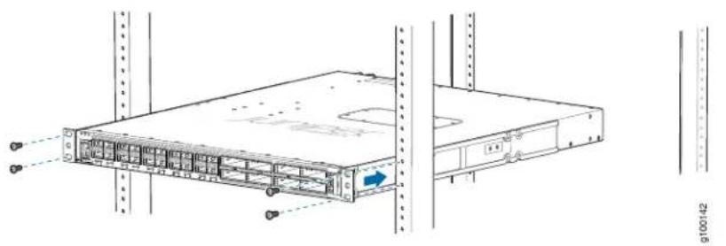
natural_image
Technical line drawing of a server rack unit with mounting holes and drive bays (no text or symbols)- Continue to support the ACX6360 while sliding the rear-mounting blades into the channel of the side mounting-rails and securing the blades to the rack. Use four
mounting screws (and cage nuts and washers if your rack requires them) to attach the blade to the rack. Tighten the screws. See Figure 22 on page 69
Figure 22: Slide Mounting Blades into Mounting Rail

natural_image
Technical diagram of a server rack with mounting brackets and a blue directional arrow indicating movement (no text or symbols present)- Ensure that the ACX6360 chassis is level by verifying that all the screws on the front of the rack are aligned with the screws at the back of the rack.
Related Documentation
ACX6360 Installation Overview on page 63.
•Connecting the ACX6360 Grounding Cable on page 70
Connecting the ACX6360 to Power
- Connecting the ACX6360 Grounding Cable on page 70
- Connecting AC Power to the ACX6360 on page 71
- Connecting DC Power to the ACX6360 on page 74
Connecting the ACX6360 Grounding Cable
To meet safety and electromagnetic interference (EMI) requirements and to ensure proper operation, you must connect the ACX6360 device to earth ground before you connect it to power.
Figure 23 on page 70 shows the location of the ACX6360 grounding points.
Figure 23: ACX6360 Grounding Points

Before you connect earth ground to the protective earthing terminal of an ACX6360 device, ensure that a licensed electrician has attached an appropriate grounding lug to the grounding cable.

CAUTION: Using a grounding cable with an incorrectly attached lug can damage the switch.

NOTE: Mount your device in the rack before attaching the grounding lug to the switch. See "Unpacking and Mounting the ACX6360" on page 65.
Ensure that you have the following parts and tools available:
- Grounding cable for your ACX6360 device—The grounding cable must be 14 AWG (2 mm²), minimum 90°C wire, or as permitted by the local code.
- Grounding lug for your grounding cable—The grounding lug required is a Panduit LCD10-10A-L or equivalent.
- Two SAE 10-32 washers and screws—To attach the grounding lug to the protective earthing terminal.
- Screwdriver to attach the screws.
An AC-powered ACX6360 chassis gains additional grounding when you plug the power supply in the switch into a grounded AC power outlet by using an AC power cord appropriate for your geographical location. See "ACX6360 AC Power Cord Specifications" on page 38.
To connect earth ground to an ACX6360 device:
- Attach one end of the grounding cable to an appropriate earth ground site, such as the mounting rack.
- Position the grounding lug over the protective earthing terminal on the side of the chassis, which is visible through the mounting bracket.
- Secure the grounding lug to the protective earthing terminal with the washers and screws. See Figure 24 on page 71.
Figure 24: Connecting a Grounding Cable to an ACX6360 Device

natural_image
Technical diagram showing cable installation and connection details (no text or symbols)- Dress the grounding cable and ensure that it does not touch or block access to other device components and that it does not drape where people could trip over it.
Connecting AC Power to the ACX6360
The ACX6360 is shipped from the factory with two power supplies. Each power supply is a hot-removable and hot-insertable field-replaceable unit (FRU) when the second power supply is installed and running. You can install replacement power supplies in the two slots next to the fan modules without powering off the device or disrupting the routing functions.
Ensure that you have the following parts and tools available:
- ESD grounding strap
- Power cord or cords appropriate for your geographical location available to connect AC power to the ACX6360 (see "ACX6360 AC Power Cord Specifications" on page 38).
Before you begin connecting AC power to the device:
- Read "General Electrical Safety Guidelines and Warnings" on page 151 and "Action to Take After an Electrical Accident" on page 152.
- Ensure that you have taken the necessary precautions to prevent electrostatic discharge (ESD) damage (see "Prevention of Electrostatic Discharge Damage" on page 153).
- Ensure that you have connected the ACX6360 chassis to earth ground.

CAUTION: Before you connect power to the switch, a licensed electrician must attach a cablelug to the grounding and power cablesthatyousupply. A cable with an incorrectly attached lug can damage the switch (for example, by causing a short circuit). To meet safety and electromagnetic interference (EMI) requirements and to ensure proper operation, you must connect the chassis to earth ground before you connect it to power. For installations that require a separate grounding conductor to the chassis, use the protective earthing terminal on the switch chassis to connect to the earth ground. For instructions on connecting earth ground, see "Connecting the ACX6360 Grounding Cable" on page 70. The switch gains additional grounding when you plug the power supply in the switch into a grounded AC power outlet by using the AC power cord appropriate for your geographical location (see "ACX6360 AC Power Supply Description" on page 34).
- Install the power supply in the chassis following the instructions in "Installing a Power Supply in an ACX6360" on page 101.

CAUTION: Do not mix AC and DC power supplies in the same chassis.

NOTE: Each power supply must be connected to a dedicated power source outlet.
To connect AC power to an ACX6360:
- Attach an electrostatic discharge (ESD) grounding strap to your barewrist, and connect the strap to an approved site ESD grounding point.
- Ensure that the power supplies are fully inserted in the chassis and the latches are secure. If only one power supply is installed, ensure that a blank coverpanel is installed over the second power supply slot.
- Locate the power cord or cords shipped with the ACX6360; the cords have plugs appropriate for your geographical location. See "ACX6360 AC Power Cord Specifications" on page 38.

WARNING: Ensure that the power cord does not block access to router components or drape where people could trip on it.
- Connect each power supply to the power sources. Insert the coupler end of the power cord into the AC power cord inlet on the AC power supply faceplate.
- Push the power cord retainer onto the power cord (see Figure 25 on page 73).
Figure 25: Connecting an AC Power Cord to an AC Power Supply in an ACX6360
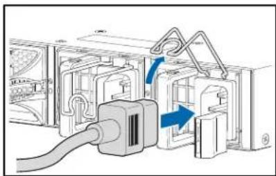
natural_image
Diagram of a device with a cable inserted into a housing, showing internal components and a blue directional arrow (no text or symbols present)
natural_image
Technical diagram of an air conditioning unit with internal tubing and a blue arrow indicating direction (no text or symbols)1— Power cord retainer
- If the AC power source outlet has a power switch, set it to the off (O) position.

NOTE: The device powers on as soon as power is provided to the power supply. There is no power switch on the device.
- Insert the power cord plug into an AC power source outlet.
- If the AC power source outlet has a power switch, set it to the on (I) position.
- Verify that the AC and DC LEDs on each power supply are lit green.
If the amber fault LED is lit, remove power from the power supply, and replace the power supply (see "Removing a Power Supply from the ACX6360" on page 100). Do not remove the power supply until you have a replacement power supply ready: the power supplies or a blank cover panel must be installed in the ACX6360 to ensure proper airflow.

CAUTION: Replace a failed power supply with a blank panel or newpower supply within 1 minute of removal to prevent the chassis from overheating.
Connecting DC Power to the ACX6360
The ACX6360 is shipped from the factory with two power supplies. Each power supply is a hot-removable and hot-insertable field-replaceable unit (FRU) when the second power supply is installed and running. You can install replacement power supplies in the two slots next to the fan modules without powering off the device or disrupting the routing functions.

WARNING: DC-powered ACX6360 models are intended for installation only in a restricted-access location.

NOTE: The battery returns of the DC power supply must be connected as an isolated DC return (DC-I).
Ensure that you have the following parts and tools available:
- ESD grounding strap
- DC power source cables (14–16 AWG) with ring lug (Molex 190700069 or equivalent) (not provided)
• Phillips (+) screwdriver, number 2 (not provided) - Multimeter (not provided)
Before you begin connecting DC power to the ACX6360:
- Read "General Electrical Safety Guidelines and Warnings" on page 151, "DC Power Electrical Safety Guidelines" on page 155, and the following warnings:
• DC Power Copper Conductors Warning on page 156
• DC Power Disconnection Warning on page 156
• DC Power Grounding Requirements and Warning on page 158
• DC Power Wiring Sequence Warning on page 159
• DC Power Wiring Terminations Warning on page 160
- Ensure that you have taken the necessary precautions to prevent electrostatic discharge (ESD) damage (see "Prevention of Electrostatic Discharge Damage" on page 153).
- Ensure that you have connected the ACX6360 chassis to earth ground.

CAUTION: Before you connect power to the switch, a licensed electrician must attach a cable lug to the grounding and power cables that you supply. A cable with an incorrectly attached lug can damage the switch (for example, by causing a short circuit). To meet safety and electromagnetic interference (EMI) requirements and to ensure proper operation, you must
connect the chassis to earth ground before you connect it to power. For installations that require a separate grounding conductor to the chassis, use the protective earthing terminal on the switch chassis to connect to the earth ground. For instructions on connecting earth ground, see "Connecting the ACX6360 Grounding Cable" on page 70.
- Install the power supply in the chassis following the instructions in “Installing a Power Supply in an ACX6360” on page 101.

CAUTION: Do not mix AC and DC power supplies in the same chassis.

NOTE: Each power supply must be connected to a dedicated power source outlet.
To connect DC power to an ACX6360:
-
Attach an electrostatic discharge (ESD) grounding strap to your bare wrist, and connect the strap to an approved site ESD grounding point.
-
Verify that the DC power cables are correctly labeled before making connections to the power supply. In a typical power distribution scheme where the return is connected to chassis ground at the battery plant, you can use a multimeter to verify the resistance of the -48V and RTN DC cables to chassis ground:
-
The cable with very low resistance (indicating a closed circuit) to chassis ground is positive (+) and will be installed on the V+ (return) DC power input terminal.
- The cable with very high resistance (indicating an open circuit) to chassis ground is negative (-) and will be installed on the V- (input) DC power input terminal.

CAUTION: You must ensure that power connections maintain the proper polarity. The power source cables might be labeled (+) and (−) to indicate their polarity. There is no standard color coding for DC power cables. The color coding used by the external DC power source at your site determines the color coding for the leads on the power cables that attach to the DC power input terminals on each power supply.
- Ensure that the input circuit breaker is open so that the voltage across the DC power source cable leads is 0 V and that the cable leads do not become active while you are connecting DC power.

NOTE: The V+ terminals are referred to as +RTN, and V- terminals are referred to as -48 V in "DC Power Wiring Sequence Warning" on page 159 and "DC Power Electrical Safety Guidelines" on page 155.
-
Ensure that the power supplies are fully inserted in the chassis.
-
Remove the terminal block cover. The terminal block cover is a piece of clear plastic that snaps into place over the terminal block (see Figure 26 on page 77).
-
Remove the screws on the terminals using the screwdriver. Save the screws.

WARNING: Ensure that the power cables do not block access to device components or drape where people can trip on them.
- Connect each power supply to the power sources. Secure power source cables to the power supplies by screwing the ring lugs attached to the cables to the appropriate terminals by using the screw from the terminals (see Figure 26 on page 77 and
Figure 27 on page 77. The ACX6360 is designed to operate with a DC power supply that has a single, non-redundant, feed input. For source redundancy, two DC power supplies must be installed; connect source (A) to one power supply and connect source (B) to the second power supply. This configuration provides the commonly deployed A/B feed redundancy for the system.
The terminal block of the power supply has four terminals labeled V+, V+, V−, and V− for connecting DC power source cables labeled positive (+) and negative (−). The V+ terminals are shunted internally together, as are the V- terminals.

CAUTION: The connection between each power source and power supply must include a circuit breaker.
Do not connect two sources to a single power supply because doing so can potentially cause circulating current in feed wires whenever there is any difference in the voltage of the two sources.
a. Secure the ring lug of the positive (+) DC power source cable to the V+ terminal on the DC power supply.
b. Secure the ring lug of the negative (−) DC power source cable to the V- terminal on the DC power supply.
c. Tighten the screws on the power supply terminals until snug using the screwdriver. Do not overtighten—apply between 5 in-lb (0.56 Nm) and 6 in-lb (0.68 Nm) of torque to the screws.
Figure 26: DC Power Supply Faceplate for an ACX6360

| 5-1- ESD grounding pointShunt negative input terminals (+ | |
| 6-2- Fault LEDShunt positive input terminals (-48V) | |
| 7-3- Output LEDTerminal block | |
| 8-4- Input LEDLatch lever |

CAUTION: The V+ terminals are shunted internally together, as are the V- terminals. The same polarity terminal can be wired together from the same source to provide an additional current path in a higher power chassis. Do not connect the terminals to different sources.
Figure 27: Securing Ring Lugs to the Terminals on the ACX6360 DC Power Supply
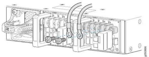
- Replace the terminal block cover.
- Close the input circuit breaker.

NOTE: The device powers on as soon as power is provided to the power supply. There is no power switch on the device.
- Verify that the IN and OUT LEDs on the power supply are lit green and are on steadily.
Related Documentation
ACX6360 Power System on page 33.
- ACX6360 Chassis Grounding Cable and Lug Specifications on page 46
Connecting the ACX6360 to External Devices
- Connecting the ACX6360 to a Management Ethernet Device on page 78
- Connecting the ACX6360 to a Management Console on page 79
Connecting the ACX6360 to a Management Ethernet Device
You can monitor and manage the ACX6360 by using a dedicated management channel. The device has two management ports—a 10/100/1000BASE-T RJ-45 port for copper connections and a Gigabit Ethernet SFP port for fiber-optic connections. Use the management ports to connect the device to a network for out-of-band management.

NOTE: You cannot use the management ports to perform the initial configuration of the ACX6360. You must configure the management ports through the console connection before you can successfully connect to the ACX6360 by using these ports. See "Configuring Junos OS on the ACX6360" on page 80.
Ensure that you have an appropriate cable available. See “Cable Specifications for Console and Management Connections for the ACX6360” on page 60.
To connect an ACX6360 to a network for out-of-band management (see Figure 28 on page 79):
- Connect one end of the cable to one of the two management ports—labeled MGMT—on the ACX6360.
- Connect the other end of the cable to the management network device.
Figure 28: Connecting an ACX6360 to a Network for Out-of-Band Management

flowchart
graph LR
    A["MGMT<br>To Management port<br>(on device)"] --> B["Management network"]
    B --> C["Management PC"]
    B --> D["Management PC"]
    B --> E["Management PC"]
Connecting the ACX6360 to a Management Console
The ACX6360 has a console port with an RJ-45 connector. Use the console port to connect the router directly to a management console, such as a laptop, or to a console server.
Ensure that you have an RJ-45 to DB-9 rollover cable available. An RJ-45 cable with an RJ-45 to DB-9 adapter is provided with the ACX6360.

NOTE: If your laptop or PC does not have a DB-9 male connector pin and you want to connect your laptop or PC directly to the ACX6360, use a combination of the RJ-45 cable and RJ-45 to DB-9 adapter supplied with the router and a USB toDB-9 male adapter. You must provide the USB toDB-9 male adapter.
To connect the ACX6360 to a management console (see Figure 29 on page 79 or Figure 30 on page 80):
- Connect one end of the Ethernet cable to the console port (labeled CON).
- Connect the other end of the Ethernet cable directly to a management console or console server.
Figure 29: Connecting the ACX6360 Directly to a Management Console
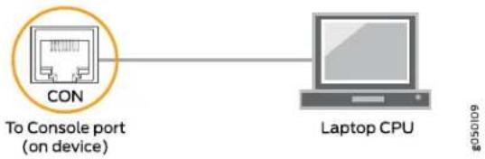
flowchart
graph LR
    A["CON"] --> B["Laptop CPU"]
    style A fill:#f9f,stroke:#333
    style B fill:#ccf,stroke:#333
Figure 30: Connecting the ACX6360 to a Management Console Through a Console Server
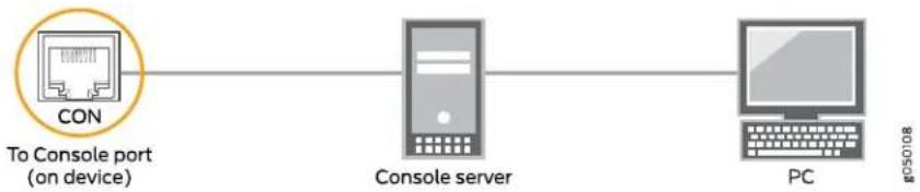
flowchart
graph LR
    A["CON"] --> B["Console server"]
    B --> C["PC"]
    style A fill:#f9f,stroke:#333
    style B fill:#ccf,stroke:#333
    style C fill:#cfc,stroke:#333
See Also
Related ACX6360 Port Panel on page 24. Documentation •ACX6360 Management Panel on page 30
Performing Software Configurations on the ACX6360
• Performing the Initial Software Configuration for the ACX6360 on page 80
- Changing Operational Modes on the ACX6360 on page 82
Performing the Initial Software Configuration for the ACX6360
You must perform the initial configuration of the ACX6360 through the console port by using the Junos OS command-line interface (CLI).
Before you begin connecting and configuring an ACX6360, set the following parameter values on the management console or console server:
- Baud Rate—9600
- Flow Control—None
- Data—8
- Parity—None
- Stop Bits—1
• DCD State—Disregard
To connect and configure the ACX6360 from the console:
- Connect the console port to a laptop or PC by using the supplied RJ-45 cable and RJ-45 to DB-9 adapter. The console port (labeled CON) is located on the management panel of the ACX6360 (see "Connecting the ACX6360 to a Management Console" on page 79 for more information).
- Log in as root. There is no password. If the software boots before you connected to the console port, you might need to press the Enter key for the prompt to appear.
login: root - Start the CLI.
root@% cli
- Enter configuration mode.
root> configure
- Add a password to the root administration user account.
[edit]
root@# set system root-authentication plain-text-password
New password: password
Retype new password: password
- (Optional) Configure the name of the ACX6360. If the name includes spaces, enclose the name in quotation marks (" " ).
[edit]
root@# set system host-name host-name
- Configure the default gateway.
[edit]
root@# set routing-options static route default next-hop address
- Configure the IP address and prefix length for the management interface.
[edit]
root@# set Interfaces em0 unit 0 family Inet address address/prefix-length

CAUTION: Although the CLI permits you to configure two management Ethernet interfaces within the same subnet, only one interface is usable and supported at a time.

NOTE: The management port em0 is on the port panel and the management port em2 is on the FRU end of the device.
- (Optional) Configure the static routes to remote prefixes with access to the management port.
[edit]
root@# set routing-options static route remote-prefix next-hop destination-ip retain no-readvertise
- Enable the Telnet service.
[edit]
root@# set system services telnet

NOTE: When Telnet is enabled, you cannot log in to an ACX6360 through Telnet by using root credentials. Root login is allowed only for SSH access.
- Enable SSH service for root login.
[edit]
root@# set system services SSH
- Commit the configuration to activate it on the device.
[edit]
root@# commit
Changing Operational Modes on the ACX6360
The ACX6360 can be used as either a transponder or a router. As a transponder, the ACX6360-OX has 16 100-Gbps ports that provide 1-to-1 cross-connects for pass-through connections of client interface traffic to line optical interfaces. As a router the ACX6360-OR provides IP/MPLS routing services.
The mode that the ACX6360 operates in, is determined by the software installed on the chassis. Each mode has its own Junos OS software.
- Router mode—Install the Junos-vmhost-base8-Install-acxor-x86-64 image.
- Transponder mode—Install the junos-vmhost-base8-install-acxox-x86-64 image.

NOTE: For information on installing Junos OS, see Software Installation and Upgrade Guide.
To change the ACX6360 chassis from router mode to transponder mode, all you need to do is install the transponder mode Junos OS software. Also, when changing from transponder mode to router mode, all you need to do is install the router mode Junos OS software.

NOTE: When you change the operational mode of the ACX6360, you lose all of the configuration settings that you configured in the previous mode. After changing modes, the system will come up in its factory (default) configuration.
Related Documentation
ACX6360 Management Cable Specifications and Pinouts on page 60.
Transponder Mode on the ACX6360
• Understanding Transponder Mode on the ACX6360 on page 83
• The Transport-CCC Forwarding Sandbox on page 83
• The Circuit Cross-Connect Configuration on page 86
• Understanding Ethernet Fault Propagation on page 87
• Verifying the Circuit Cross-Connect Configuration on page 89
- Resetting the Circuit Cross-Connect Defaults on page 91
- Troubleshooting Information on page 92
Understanding Transponder Mode on the ACX6360
The ACX6360 can be used as either a transponder or a router. As a transponder, the ACX6360-OX has sixteen 100-Gbps ports that provide 1-to-1 cross-connects for pass-through connections of client interface traffic to line optical interfaces. As a router the ACX6360-OR provides IP/MPLS routing services. (For information on changing the operational mode, see "Changing Operational Modes on the ACX6360" on page 82.)
When in transponder mode, circuit cross-connect (CCC) is used to provide transparent point-to-point connections. This can be in the form of interface to interface, LSP to LSP, interface to LSP, or LSP to interface.
Figure 31 on page 83 shows how the ACX6360-OX transponder can be used in your network.
Figure 31: The ACX6360-OX Transponder in Your Network

flowchart
graph LR
    R1[" R1 "] -->|if1| A1[" A1 "]
    A1 -->|if2| A1
    A1 -->|if3| A2[" A2 "]
    A2 -->|if4| A2
    A2 -->|if5| R2[" R2 "]
    A2 -->|if6| R2
    A1 -->|ACX6360-OX| A1
    A2 -->|ACX6360-OX| A2
    style A1 fill:#f9f,stroke:#333
    style A2 fill:#f9f,stroke:#333
The Transport-CCC Forwarding Sandbox
Figure 32 on page 84 shows the logical view of the sandboxes that are created in the system for the transport-ccc. The default sandbox sb-ccc is owned and managed by the CCC client. When the CCC client opens the sb-ccc sandbox, it gets a complete list of the available ports in the ACX6360-OX. The ports that are visible in the sb-ccc sandbox are virtual ports. Each virtual port corresponds to one physical et-0/x/y port.
Figure 32: Transport-ccc Sandbox

flowchart
graph TD
    A["et-0/0/0 In"] --> B["p0"]
    C["et-0/0/1 In"] --> D["p1"]
    E["et-0/0/7 In"] --> F["p7"]
    G["et-0/0/8 In"] --> H["p6"]
    I["et-0/0/9 In"] --> J["p9"]
    K["et-0/0/15 In"] --> L["p15"]
    B --> M["p0"]
    D --> N["p1"]
    F --> O["p7"]
    H --> P["p8"]
    J --> Q["p9"]
    L --> R["p15"]
    M --> S["et-0/1/0 Out"]
    N --> T["et-0/1/1 Out"]
    O --> U["et-0/1/7 Out"]
    P --> V["et-0/1/8 Out"]
    Q --> W["et-0/1/9 Out"]
    R --> X["et-0/1/15 Out"]
g300518
The default sandbox configuration should not be modified. If the sandbox configuration is modified for any reason, you must restart the circuit cross-connect process or reboot the system. Only one forwarding sandbox can be configured on the ACX6360-OX.
Following is the default sandbox configuration. The startup script on the ACX6360-OX automatically creates the default sandbox configuration.
user@host> show forwarding-options forwarding-sandbox sbCCC
port port-0/0/0 {
    interface et-0/0/0;
}
port port-0/0/1 {
    interface et-0/0/1;
}
port port-0/0/10 {
    interface et-0/0/10;
}
port port-0/0/11 {
    interface et-0/0/11;
}
port port-0/0/12 {
    interface et-0/0/12;
}
port port-0/0/13 {
    interface et-0/0/13;
}
port port-0/0/14 {
    interface et-0/0/14;
}
port port-0/0/15 {
    interface et-0/0/15;
}
port port-0/0/2 {
    interface et-0/0/2;
}
port port-0/0/3 {
    interface et-0/0/3;
}
port port-0/0/4 {
    interface et-0/0/4;
}
port port-0/0/5 {
    interface et-0/0/5;
}
port port-0/0/6 {
    interface et-0/0/6;
}
port port-0/0/7 {
    interface et-0/0/7;
}
port port-0/0/8 {
    interface et-0/0/8;
}
port port-0/0/9 {
    interface et-0/0/9;
}
port port-0/1/0 {
    interface et-0/1/0;
}
port port-0/1/1 {
    interface et-0/1/1;
}
port port-0/1/10 {
    interface et-0/1/10;
}
port port-0/1/11 {
    interface et-0/1/11;
}
port port-0/1/12 {
    interface et-0/1/12;
}
port port-0/1/13 {
    interface et-0/1/13;
}
port port-0/1/14 {
    interface et-0/1/14;
}
port port-0/1/15 {
    interface et-0/1/15;
}
port port-0/1/2 {
    interface et-0/1/2;
}
port port-0/1/3 {
    interface et-0/1/3;
}
port port-0/1/4 {
    interface et-0/1/4;
}
port port-0/1/5 {
    interface et-0/1/5;
}
port port-0/1/6 {
    interface et-0/1/6;
}
port port-0/1/7 {
    interface et-0/1/7;
}
port port-0/1/8 {
    interface et-0/1/8;
}
port port-0/1/9 {
    interface et-0/1/9;
}
The Circuit Cross-Connect Configuration
The default circuit cross-connect configuration is configured through the startup script at system startup. You can define or modify the circuit cross-connects based on your requirements. Following is the default circuit cross-connect configuration.
user@host> show circuit-cross-connect: forwarding-sandbox forwarding-sandbox-name sbCCC
cross-connects {
    cross-connect ccc-0 {
    endpoint1 port-0/0/0;
    endpoint2 port-0/1/0;
    admin-state CC_ADMIN_UP;
    }
    cross-connect ccc-1 {
    endpoint1 port-0/0/1;
    endpoint2 port-0/1/1;
    admin-state CC_ADMIN_UP;
    }
    cross-connect ccc-10 {
    endpoint1 port-0/0/10;
    endpoint2 port-0/1/10;
    admin-state CC_ADMIN_UP;
    }
    cross-connect ccc-11 {
    endpoint1 port-0/0/11;
    endpoint2 port-0/1/11;
    admin-state CC_ADMIN_UP;
    }
    cross-connect ccc-12 {
    endpoint1 port-0/0/12;
    endpoint2 port-0/1/12;
    admin-state CC_ADMIN_UP;
    }
    cross-connect ccc-13 {
    endpoint1 port-0/0/13;
    endpoint2 port-0/1/13;
    admin-state CC_ADMIN_UP;
    }
    cross-connect ccc-14 {
    endpoint1 port-0/0/14;
    endpoint2 port-0/1/14;
    admin-state CC_ADMIN_UP;
    }
    cross-connect ccc-15 {
    endpoint1 port-0/0/15;
    endpoint2 port-0/1/15;
    admin-state CC_ADMIN_UP;
    }
    cross-connect ccc-2 {
    endpoint1 port-0/0/2;
endpoint2 port-0/1/2;
admin-state CC_ADMIN_UP;
}
cross-connect ccc-3 {
    endpoint1 port-0/0/3;
    endpoint2 port-0/1/3;
    admin-state CC_ADMIN_UP;
}
cross-connect ccc-4 {
    endpoint1 port-0/0/4;
    endpoint2 port-0/1/4;
    admin-state CC_ADMIN_UP;
}
cross-connect ccc-5 {
    endpoint1 port-0/0/5;
    endpoint2 port-0/1/5;
    admin-state CC_ADMIN_UP;
}
cross-connect ccc-6 {
    endpoint1 port-0/0/6;
    endpoint2 port-0/1/6;
    admin-state CC_ADMIN_UP;
}
cross-connect ccc-7 {
    endpoint1 port-0/0/7;
    endpoint2 port-0/1/7;
    admin-state CC_ADMIN_UP;
}
cross-connect ccc-8 {
    endpoint1 port-0/0/8;
    endpoint2 port-0/1/8;
    admin-state CC_ADMIN_UP;
}
cross-connect ccc-9 {
    endpoint1 port-0/0/9;
    endpoint2 port-0/1/9;
    admin-state CC_ADMIN_UP;
}
Understanding Ethernet Fault Propagation
On the ACX6360-OX, when a local fault is received on the line side (et-0/1/y), it sends the local fault out on the client side (et-0/0/x). The client port then receives a remote fault (RF), which is then sent over on the line side (et-0/1/y). Figure 33 on page 88 shows the local fault (LF) detection on the line side.
Figure 33: Local Fault Detection on the Line Side
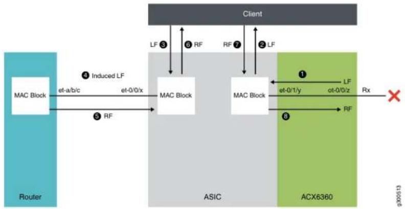
flowchart
graph TD
    A["MAC Block"] -->|el-a/b/c| B["ASIC"]
    B -->|et-0/0/x| C["ACX6360"]
    C -->|RF| B
    B -->|LF ③| D["Client"]
    B -->|LF ⑥ RF| D
    B -->|LF ⑦ ② LF| D
    C -->|LF ① et-0/1/y| E["ACX6360"]
    C -->|RF| E
    E --> F["Rx"]
    style A fill:#4CAF50,stroke:#388E3C
    style B fill:#4CAF50,stroke:#388E3C
    style C fill:#4CAF50,stroke:#388E3C
    style D fill:#4CAF50,stroke:#388E3C
    style E fill:#4CAF50,stroke:#388E3C
    subgraph Router
        A
        B
        C
    end
    subgraph ASIC
        B
        C
    end
    subgraph ACX6360
        C
        B
        C
    end
On the ACX6360-OX, when the client port (et-0/0/x) sends a local fault to the connected router, it receives a remote fault on the client port (et-0/0/x) and then it sends the remote fault out on the line side (et-0/1/y). Figure 34 on page 88 Shows the local fault detected by the client-side router.
Figure 34: Local Fault Detection by the Client-side Router

flowchart
graph TD
    subgraph Router
        A["MAC Block"] -->|Rx et-a/b/c Tx| B["MAC Block"]
        B -->|Rx et-0/0/x| C["Client"]
        D["RF"] -->|1| B
        E["RF"] -->|2| F["Client"]
        G["RF"] -->|3| H["Client"]
    end

    subgraph ASIC
        I["MAC Block"] --> J["ACX6360"]
        K["MAC Block"] --> L["ACX6360"]
        M["ACX6360"] --> N["RF"]
    end

    subgraph ACX6360
        O["ACX6360"] --> P["RF"]
    end

    style Router fill:#4CAF50,stroke:#333
    style ASIC fill:#4CAF50,stroke:#333
    style ACX6360 fill:#4CAF50,stroke:#333
On the ACX6360-OX, when the client port (et-0/0/x) receives a local fault, it sends the local fault out on the line side (et-0/1/y) and then forwards the received remote fault (et-0/1/y) to the client port (et-0/0/x). Figure 35 on page 89 shows a local fault detected by the client-side interface.
Figure 35: Local Fault Detection by the Client-side Interface
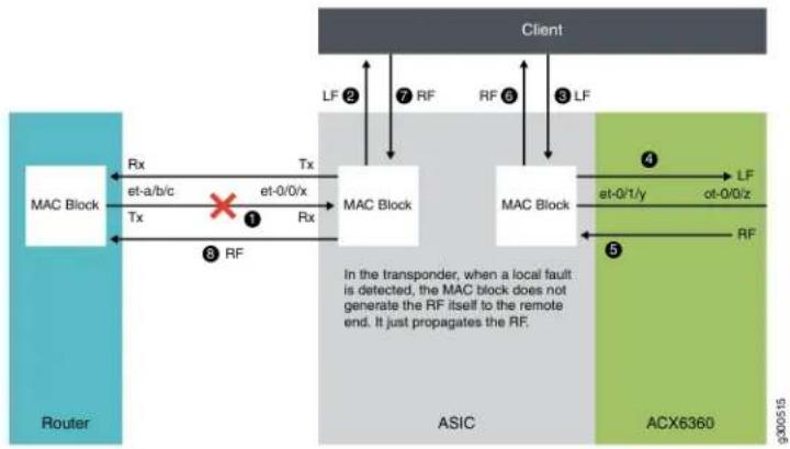
flowchart
graph TD
    subgraph Router
        A["MAC Block"] -->|Rx et-a/b/c Tx| B["MAC Block"]
        B -->|Tx et-0/0/x| C["MAC Block"]
        C -->|Rx| D["MAC Block"]
        D -->|RF| B
    end

    subgraph ASIC
        E["MAC Block"] -->|et-0/t/y| F["MAC Block"]
        F -->|LF ot-0/0/z| G["ACX6360"]
        G -->|RF| F
    end

    subgraph Client
        H["Client"] -->|LF 2| I["MAC Block"]
        I -->|7 RF| J["MAC Block"]
        J -->|RF 6| K["MAC Block"]
        K -->|3 LF| L["MAC Block"]
        L -->|4 LF| M["ACX6360"]
        M -->|5 RF| N["MAC Block"]
        N -->|1 et-0/0/x| O["MAC Block"]
        O -->|1 RX| P["MAC Block"]
    end

    style Router fill:#f9f,stroke:#333
    style ASIC fill:#ccf,stroke:#333
    style Client fill:#cfc,stroke:#333
When a remote fault is sent by another ACX6360-OX, the remote fault is forwarded transparently to the client-side router. On the ACX6360-OX, when a line port (et-0/1/y) receives a remote fault, it forwards the remote fault out on the client port (et-0/0/x).
Figure 36 on page 89 shows the remote fault handling.
Figure 36: Remote Fault

flowchart
graph TD
    A["Client"] -->|③ RF| B["ASIC"]
    A -->|② RF| C["ACX6360"]
    B -->|① et-0/1/y| C
    B -->|④ RX| D["MAC Block"]
    D -->|Rx et-a/b/c| E["Router"]
    D -->|Tx et-0/0/x| F["MAC Block"]
    F -->|Rx| G["MAC Block"]
    G -->|RF| H["ACX6360"]
    style A fill:#f9f,stroke:#333
    style B fill:#ccf,stroke:#333
    style C fill:#cfc,stroke:#333
    style D fill:#ffc,stroke:#333
    style E fill:#cfc,stroke:#333
    style F fill:#cfc,stroke:#333
    style G fill:#cfc,stroke:#333
    style H fill:#fcc,stroke:#333
Verifying the Circuit Cross-Connect Configuration
Purpose Use the following procedure to verify that your circuit cross-connect configuration is correct:
Action 1. Verify the contents of the /var/db/scripts/jet folder:
user@host:/var/db/scripts/jet # ls
-lrt total 220 drwxrws--x 2 user 512 server-extension
-rw-r--r-- 1 user 42361 CrossConnect_pb2.py
-rw-r--r-- 1 user 10970 CrossConnect_pb2_grpc.py
-rw-r--r-- 1 user 5694 README
-rw-r--r-- 1 user 4029 authentication_service_pb2.py
-rw-r--r-- 1 user 1449 authentication_service_pb2_grpc.py
-rwxr-xr-x 1 user 81049 ccc.py
-rw-r--r-- 1 user 9247 circuit-cross-connect.yang
-rw-r--r-- 1 user 44739 management_service_pb2.py
-rw-r--r-- 1 user 4418 management_service_pb2_grpc.py
- Verify the Juniper Extension Toolkit (JET) infrastructure configuration:
user@host# show system services
ssh {
    root-login allow;
}
extension-service {
    request-response {
    grpc {
    clear-text;
    }
    }
    notification {
    port 1883;
    allow-clients {
    address 127.0.0.1/32;
    }
    }
traceoptions {
    flag all;
    flag config;
}
user@host# show system extensions
extension-service {
    application {
    file ccc.py {
    arguments "-m cfg";
    daemonize;
    username root;
    }
    }
}
- Verify that the circuit cross-connect Yang package is installed.
user@host> show system yang package
Package ID :ccc
YANG Module(s) :circuit-cross-connect.yang
Action Script(s) :ccc.py
Translation Script(s) :*
Translation script status is disabled
If the Yang circuit cross-connect package is not installed, do the following to install the package:
a. On the shell, go to the /var/db/scripts/jet folder.
b. Start the CLI and enter the following command:
user@host> request system yang add package ccc module circuit-cross-connect.yang action-script ccc.py
- Verify that all the circuit cross-connect related processes are running on the shell:
a. Verify that the JET service process (jsd) is running on the routing engine:
user@host: RE:0% ps auwx | grep jsd
user 5957 0.0 0.7 497844 22832 - I Wed22 1:28.46 /usr/sbin/jsd -N
b. Verify that jsd is listening on TCP port 51051:
user@host: ~ # netstat -An | grep 51051
ffffff80275869000 tcp4 0 0 128.0.0.1.51051 *.* LISTEN
c. Verify that the circuit cross-connect configuration handling script is running on the routing engine:
user@host: RE:0% ps auwx | grep ccc
user 14509 0.0 0.7 34852 22252 - S 15:13 0:00.97 /usr/libexec/ui/cscript.crypto -mjet -Q -j -f ccc.py -a -m cfg -Jroot
Resetting the Circuit Cross-Connect Defaults
If you are facing any issues related to circuit cross-connect creation and want to reset the system to its default configuration, follow these steps:
- Remove the sandbox and the circuit cross-connect configuration:
user@host> delete circuit-cross-connect:forwarding-sandbox
user@host> delete forwarding-options forwarding-sandbox sbCCC
user@host> commit
- Delete the CCC Yang package:
user@host> request system yang delete ccc
- Configure the system by running the startup script manually from the shell:
user@host> /usr/sbin/acx6360-ccc-setup.sh
- Verify that the Yang package is installed:
user@host> show system yang package
- Verify that the default sandbox configuration and the circuit cross-connects are installed on the box. See "Verifying the Circuit Cross-Connect Configuration" on page 89.
Troubleshooting Information
The circuit cross-connect log files are located at the following locations:
/var/log/ccc.py-user-cfg.log
/var/log/ccc.py-regress-op.log
/var/log/jet.log
/var/log/jsd
You can use the following CLI commands to troubleshoot circuit cross-connects:
- To verify endpoints:
user@host> show circuit-cross-connect all-endpoints forwarding-sandbox-name sbCCC
• To verify all circuit cross-connects:
user@host> show circuit-cross-connect all-cross-connects forwarding-sandboxname sbCCC
Cross-connects:
ccc-0: port-0/0/0(et-0/0/0) <--> port-0/1/0(et-0/1/0) CC_ADMIN_UP
ccc-1: port-0/0/1(et-0/0/1) <--> port-0/1/1(et-0/1/1) CC_ADMIN_UP
ccc-10: port-0/0/10(et-0/0/10) <--> port-0/1/10(et-0/1/10) CC_ADMIN_UP
ccc-11: port-0/0/11(et-0/0/11) <--> port-0/1/11(et-0/1/11) CC_ADMIN_UP
ccc-12: port-0/0/12(et-0/0/12) <--> port-0/1/12(et-0/1/12) CC_ADMIN_UP
ccc-13: port-0/0/13(et-0/0/13) <--> port-0/1/13(et-0/1/13) CC_ADMIN_UP
ccc-14: port-0/0/14(et-0/0/14) <--> port-0/1/14(et-0/1/14) CC_ADMIN_UP
ccc-15: port-0/0/15(et-0/0/15) <--> port-0/1/15(et-0/1/15) CC_ADMIN_UP
ccc-2: port-0/0/2(et-0/0/2) <--> port-0/1/2(et-0/1/2) CC_ADMIN_UP
ccc-3: port-0/0/3(et-0/0/3) <--> port-0/1/3(et-0/1/3) CC_ADMIN_UP
ccc-4: port-0/0/4(et-0/0/4) <--> port-0/1/4(et-0/1/4) CC_ADMIN_UP
ccc-5: port-0/0/5(et-0/0/5) <--> port-0/1/5(et-0/1/5) CC_ADMIN_UP
ccc-6: port-0/0/6(et-0/0/6) <--> port-0/1/6(et-0/1/6) CC_ADMIN_UP
ccc-7: port-0/0/7(et-0/0/7) <--> port-0/1/7(et-0/1/7) CC_ADMIN_UP
ccc-8: port-0/0/8(et-0/0/8) <--> port-0/1/8(et-0/1/8) CC_ADMIN_UP
ccc-9: port-0/0/9(et-0/0/9) <--> port-0/1/9(et-0/1/9) CC_ADMIN_UP
• To verify individual circuit cross-connects:
user@host> show circuit-cross-connect cross-connect cross-connect-name ccc-0 forwarding-sandbox-name sbCCC
Cross-connect : ccc-0
Endpoint1 : port-0/0/0(et-0/0/0)
Endpoint2 : port-0/1/0(et-0/1/0)
Admin-state : CC_ADMIN_UP
Related Documentation
Powering Off the ACX6360
Before you power off an ACX6360:
- Ensure that you have taken the necessary precautions to prevent electrostatic discharge (ESD) damage. See "Prevention of Electrostatic Discharge Damage" on page 153.
- Ensure that you do not need to route traffic through the ACX6360.
- Ensure that you have the following parts and tools available to power off the ACX6360:
• An ESD grounding strap
• An external management device such as a PC - An RJ-45 to DB-9 rollover cable to connect the external management device to the console port
To power off an ACX6360:
-
Connect to the router by using one of the following methods:
-
Connect a management device to the console (CON) port on an ACX6360 by following the instructions in "Connecting the ACX6360 to a Management Console" on page 79.
-
Connect a management device to one of the two management (MGMT) ports by following the instructions in "Connecting the ACX6360 to a Management Ethernet Device" on page 78.
-
Shut down Junos OS from the external management device by issuing the request vmhost halt operational mode CLI command. This command shuts down Junos OS gracefully and preserves system state information. A message appears on the console, confirming that the operating system has halted.
user@host> request vmhost halt Halt the system ? [yes, no] (no) yes
You see the following output (or something similar) after entering the command:
Initiating vmhost halt... ok
Initiating Junos shutdown... shutdown: [pid 14318]
Shutdown NOW!
ok
Junos shutdown is in progress...
*** FINAL System shutdown message ***
System going down IMMEDIATELY
...
Operating system halted.
Please press any key to reboot.

CAUTION: The final output of any version of the request system halt command is the "The operating system has halted." Wait at least 60 seconds after first seeing this message before following the instructions in Step 4 and Step 5 to power off the ACX6360.
-
Attach an electrostatic discharge (ESD) grounding strap to your bare wrist and connect the strap to one of the ESD points on the chassis.
-
Disconnect power to the ACX6360:
- AC power supply—If the AC power source outlet has a power switch, set it to the OFF (O) position. If the AC power source outlet does not have a power switch, gently pull out the male end of the power cord connected to the power source outlet.
- DC power supply—Switch the circuit breaker on the panel board that services the DC circuit to the OFF position.
-
Remove the power source cable from the power supply faceplate:
-
AC power supply—Remove the power cord from the power supply faceplate by detaching the power cord retainer and gently pulling out the female end of the power cord connected to the power supply faceplate.
- DC power supply—Remove the screws securing the ring lugs attached to the power source cables to the power supply using the screwdriver and remove the power source cables from the power supply. Replace the screws on the terminals and tighten them.
- Uncable the device before removing it from the rack or cabinet.
Related Documentation
•Connecting the ACX6360 to External Devices on page 78
•Connecting the ACX6360 to Power on page 69
CHAPTER 4
Maintaining Components
- Maintaining the ACX6360 Fan Modules on page 97
- Maintaining the ACX6360 Power Supplies on page 100
- Maintaining the ACX6360 Transceivers and Fiber-Optic Cables on page 102
- Maintaining the SATA Solid State Drive in an ACX6360 on page 113
- Uninstalling the ACX6360 on page 116
Maintaining the ACX6360 Fan Modules
- Removing a Fan Module from the ACX6360 on page 97
• Installing a Fan Module in the ACX6360 on page 98
Removing a Fan Module from the ACX6360
The fan modules in an ACX6360 are hot-removable and hot-insertable field-replaceable units (FRUs)—you can remove and replace them without powering off the ACX6360 or disrupting routing functions.

CAUTION: Replace the fan module within 1 minute of removal to prevent chassis overheating. Before removing the fan module, ensure you have a replacement fan module available.
Before you remove a fan module from an ACX6360, ensure that you have taken the necessary precautions to prevent electrostatic discharge (ESD) damage (see "Prevention of Electrostatic Discharge Damage" on page 153).
Ensure that you have the following parts and tools available:
- ESD grounding strap
- Antistatic bag or an antistatic mat
• Phillips (+) screwdriver, number 1
To remove a fan module from an ACX6360 (see Figure 37 on page 98):
- Place the antistatic bag or the antistatic mat on a flat, stable surface.
- Attach the ESD grounding strap to your bare wrist, and connect the strap to the ESD point on the chassis.
- Using the Phillips screwdriver, loosen the locking screw (3 or 4 turns).
- Grasp the handle on the fan module and squeeze the outside of the handle to release the module.

WARNING: To avoid injury, do not touch the fan with your hands or any tools as you slide the fan module out of the chassis—the fan might still be running.
- Pull firmly to slide the fan module halfway out of the chassis.
- When the fan stops spinning, slide the fan module completely out of the chassis.
- Place the fan module in the antistatic bag or on the antistatic mat placed on a flat, stable surface.
Figure 37: Removing a Fan Module from an ACX6360
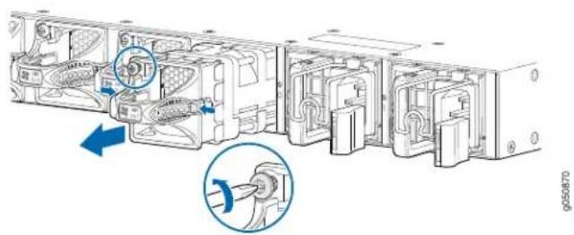

NOTE: When a fan module is removed, the CLI message Fan/Blower is Absent is logged in the system log, and the system raises a minor alarm.
Installing a Fan Module in the ACX6360
The fan modules in an ACX6360 are hot-removable and hot-insertable field-replaceable units (FRUs)—you can remove and replace them without powering off the ACX6360 or disrupting routing functions.

CAUTION: Replace the fan module within 1 minute of removal to prevent chassis overheating. Before removing the fan module, ensure you have a replacement fan module available.

NOTE: The fan module provides airflow out, which is also known as port-to-FRU airflow.
Before you install a fan module in an ACX6360, ensure that you have taken the necessary precautions to prevent electrostatic discharge (ESD) damage (see "Prevention of Electrostatic Discharge Damage" on page 153).
Ensure that you have the following parts and tools available:
- ESD grounding strap
• Phillips (+) screwdriver, number 1
To install a fan module in an ACX6360 (see Figure 38 on page 99):
- Attach the ESD grounding strap to your bare wrist, and connect the strap to the ESD point on the chassis.
- Taking care not to touch the connectors, remove the fan module from its bag.
- Align the module with the open slot on the FRU end of the ACX6360 and slide it in until it is fully seated.
- Using the Phillips screwdriver, tighten the locking screw (3 or 4 turns).
Figure 38: Installing a Fan Module in an ACX6360
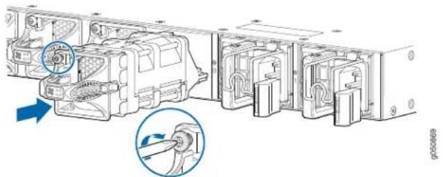
natural_image
Technical diagram of a vehicle chassis with internal components and directional arrows indicating movement (no text or symbols present)Related Documentation
Maintaining the ACX6360 Power Supplies on page 100.
•Removing and Installing ACX6360 Transceivers and Fiber-Optic Cables on page 102
Maintaining the ACX6360 Power Supplies
- Removing a Power Supply from the ACX6360 on page 100
• Installing a Power Supply in an ACX6360 on page 101
Removing a Power Supply from the ACX6360
The power supplies in an ACX6360 are hot-removable and hot-insertable field-replaceable units (FRUs) when the second power supply is installed and running. You can install replacement power supplies in the two slots next to the fan modules without powering off the device or disrupting the routing functions.
Before you remove a power supply from an ACX6360, ensure that you have taken the necessary precautions to prevent electrostatic discharge (ESD) damage (see "Prevention of Electrostatic Discharge Damage" on page 153).
Ensure that you have the following parts and tools available:
- ESD grounding strap
- Antistatic bag or an antistatic mat
• Phillips (+) screwdriver, number 2 (DC power supply)

CAUTION: Replacethepower supply with a newpowersupplywithin1minute of removal to prevent chassis overheating. Beforeeremovingthe powersupply, ensure you have a replacement power supply available.
To remove a power supply from an ACX6360 (see Figure 39 on page 101):
-
Place the antistatic bag or the antistatic mat on a flat, stable surface.
-
Attach the ESD grounding strap to your bare wrist, and connect the strap to the ESD point on the chassis.

NOTE: If you need to remove all the power supplies installed in your ACX6360, you must power off the ACX6360 before removing the power supplies. See "Powering Off the ACX6360" on page 93.
-
Disconnect power to the ACX6360:
-
AC power supply—If the AC power source outlet has a power switch, set it to the OFF (O) position. If the AC power source outlet does not have a power switch, gently pull out the male end of the power cord connected to the power source outlet.
-
DC power supply—Switch the circuit breaker on the panel board that services the DC circuit to the OFF position.
-
Remove the power source cable from the power supply faceplate:
-
AC power supply—Remove the power cord from the power supply faceplate by detaching the power cord retainer and gently pulling out the female end of the power cord connected to the power supply faceplate.
- DC power supply—Remove the screws securing the ring lugs attached to the power source cables to the power supply using the screwdriver, and remove the power source cables from the power supply. Replace the screws on the terminals and tighten them.
- Slide the locking lever toward the handle until it stops.
- Grasp the power supply handle and pull firmly to slide the power supply halfway out of the chassis.
- Place one hand under the power supply to support it and slide it completely out of the chassis. Take care not to touch power supply components, pins, leads, or solder connections.
Figure 39: Removing a Power Supply from an ACX6360
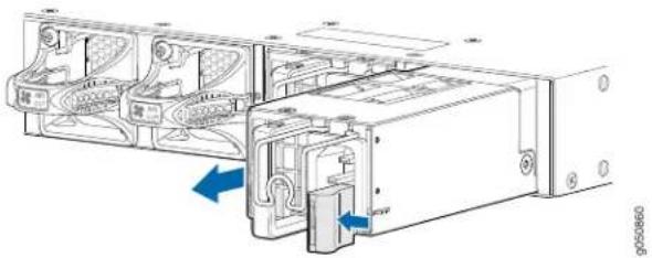
natural_image
Technical line drawing of a server rack with internal components and blue directional arrows indicating movement (no text or symbols)- Place the power supply in the antistatic bag or on the antistatic mat placed on a flat, stable surface.
Installing a Power Supply in an ACX6360
The power supplies in an ACX6360 are hot-removable and hot-insertable field-replaceable units (FRUs) when the second power supply is installed and running. You can install replacement power supplies in the two slots next to the fan modules without powering off the device or disrupting the routing functions.
Before you install a power supply in an ACX6360, ensure that you have taken the necessary precautions to prevent electrostatic discharge (ESD) damage (see "Prevention of Electrostatic Discharge Damage" on page 153).
Ensure that you have the following parts and tools available:
- ESD grounding strap
- Antistatic bag or an antistatic mat
• Phillips (+) screwdriver, number 2 (DC power supply)
To install a power supply in an ACX6360 (see Figure 40 on page 102):
- Attach the ESD grounding strap to your bare wrist, and connect the strap to the ESD point on the chassis.
- Taking care not to touch power supply components, pins, leads, or solder connections, remove the power supply from its bag.
- Using both hands, place the power supply in the power supply slot on the FRU panel of the ACX6360 and slide it in until it is fully seated and the locking lever slides into place.
Figure 40: Installing a Power Supply in an ACX6360

natural_image
Technical line drawing of a server rack with ports and connectors (no text or symbols)
NOTE: Each power supply must be connected to a dedicated power source outlet.

NOTE: If you have a Juniper Care service contract, register any addition, change, or upgrade of hardware components at
https://www.juniper.net/customers/support/tools/updateinstallbase/. Failure to do so can result in significant delays if you need replacement parts. This note does not apply if you replace existing components with the same type of component.
See Also
Related
ACX6360 Power System on page 33.
Documentation
•Connecting the ACX6360 to Power on page 69
Maintaining the ACX6360 Transceivers and Fiber-Optic Cables
-
Removing a Transceiver on page 103
• Installing a Transceiver on page 106 -
Removing a QSFP28 Transceiver on page 108
• Installing a QSFP28 Transceiver on page 109 - Disconnecting a Fiber-Optic Cable from the ACX6360 on page 110
- Connecting a Fiber-Optic Cable to the ACX6360 on page 111
- Maintaining Fiber-Optic Cables in an ACX6360 on page 112
Removing a Transceiver
The transceivers for Juniper Networks devices are hot-removable and hot-insertable field-replaceable units (FRUs). You can remove and replace them without powering off the device or disrupting device functions.

NOTE: After you remove a transceiver or when you change the media-type configuration, wait for 6 seconds for the interface to display the operational commands.
Before you begin removing a transceiver from a device, ensure that you have taken the necessary precautions for the safe handling of lasers (see "Laser and LED Safety Guidelines and Warnings" on page 143).
Ensure that you have the following parts and tools available:
- An antistatic bag or an antistatic mat
- Rubber safety caps to cover the transceiver and fiber-optic cable connector
- A dust cover to cover the port or a replacement transceiver
Figure 41 on page 105 shows how to remove a QSFP+ transceiver. The procedure is the same for all types of transceivers except the QSFP28 and CFP transceivers.
To remove a transceiver from a device:
- Place the antistatic bag or antistatic mat on a flat, stable surface.
- Wrap and fasten one end of the ESD wrist strap around your bare wrist, and connect the other end of the strap to the ESD point on the switch.
- Label the cable connected to the transceiver so that you can reconnect it correctly.

WARNING: Do not look directly into a fiber-optic transceiver or into the ends of fiber-optic cables. Fiber-optic transceivers and fiber-optic cables connected to transceivers emit laser light that can damage your eyes.

WARNING: Do not leave a fiber-optic transceiver uncovered except when inserting or removing a cable. The rubber safety cap keeps the port clean and prevents accidental exposure to laser light.

CAUTION: Do not bend fiber-optic cables beyond their minimum bend radius. An arc smaller than a few inches in diameter can damage the cables and cause problems that are difficult to diagnose.
-
Remove the cable connected to the transceiver (see Disconnecting a Fiber-Optic Cable). Cover the transceiver and the end of each fiber-optic cable connector with a rubber safety cap immediately after disconnecting the fiber-optic cables.
-
To remove an SFP, SFP+, XFP, or a QSFP+ transceiver:
a. By using your fingers, pull open the ejector lever on the transceiver to unlock the transceiver.

CAUTION: Before removing the transceiver, make sure that you open the ejector levercompletely until you hear it click. This prevents damage to the transceiver.
b. Grasp the transceiver ejector lever and gently slide the transceiver approximately 0.5 in. (1.3 cm) straight out of the port.

CAUTION: To prevent electrostatic discharge (ESD) damage to the transceiver, do not touch the connector pins at the end of the transceiver.
Figure 41: Removing an SFP, SFP+, XFP, or a QSFP+ Transceiver

1— Ejector lever
To remove a CFP transceiver:
a. Loosen the screws on the transceiver by using your fingers.
b. Grasp the screws on the transceiver and gently slide the transceiver approximately 0.5 in. (1.3 cm) straight out of the port.

CAUTION: To prevent electrostatic discharge (ESD) damage to the transceiver, do not touch the connector pins at the end of the transceiver.
-
By using your fingers, grasp the body of the transceiver and pull it straight out of the port.
-
Place the transceiver in the antistatic bag or on the antistatic mat placed on a flat, stable surface.
- Place the dust cover over the empty port or install the replacement transceiver.
Installing a Transceiver
The transceivers for Juniper Networks devices are hot-removable and hot-insertable field-replaceable units (FRUs). You can remove and replace them without powering off the device or disrupting the device functions.

NOTE: After you insert a transceiver or after you change the media-type configuration, wait for 6 seconds for the interface to display operational commands.

NOTE: We recommend that you use only optical transceivers and optical connectors purchased from Juniper Networks with your Juniper Networks device.

CAUTION: If you face a problem running a Juniper Networks device that uses a third-party optic or cable, the Juniper Networks Technical Assistance Center (JTAC) can help you diagnose the source of the problem. Your JTAC engineer might recommend that you check the third-party optic or cable and potentially replace it with an equivalent Juniper Networks optic or cable that is qualified for the device.
Before you begin to install a transceiver in a device, ensure that you have taken the necessary precautions for safe handling of lasers (see “Laser and LED Safety Guidelines and Warnings” on page 143).
Ensure that you have a rubber safety cap available to cover the transceiver.
Figure 42 on page 108 shows how to install a QSFP+ transceiver. The procedure is the same for all types of transceivers except the QSFP28 and CFP transceivers.
To install a transceiver:

CAUTION: To prevent electrostatic discharge (ESD) damage to the transceiver, do not touch the connector pins at the end of the transceiver.
-
Wrap and fasten one end of the ESD wrist strap around your bare wrist, and connect the other end of the strap to the ESD point on the switch.
-
Remove the transceiver from its bag.
-
Check to see whether the transceiver is covered with a rubber safety cap. If it is not, cover the transceiver with a rubber safety cap.

WARNING: Do not leave a fiber-optic transceiver uncovered except when inserting or removing a cable. The rubber safety cap keeps the port clean and prevents accidental exposure to laser light.
-
If the port in which you want to install the transceiver is covered with a dust cover, remove the dust cover and save it in case you need to cover the port later. If you are hot-swapping a transceiver, wait for at least 10 seconds after removing the transceiver from the port before installing a new transceiver.
-
Using both hands, carefully place the transceiver in the empty port. The connectors must face the chassis.

CAUTION: Before you slide the transceiver into the port, ensure that the transceiver is aligned correctly. Misalignment might cause the pins to bend, making the transceiver unusable.
-
Slide the transceiver in gently until it is fully seated. If you are installing a CFP transceiver, tighten the captive screws on the transceiver by using your fingers.
-
Remove the rubber safety cap when you are ready to connect the cable to the transceiver.

WARNING: Do not look directly into a fiber-optic transceiver or into the ends of fiber-optic cables. Fiber-optic transceivers and fiber-optic cables connected to transceivers emit laser light that can damage your eyes.
Figure 42: Installing a Transceiver
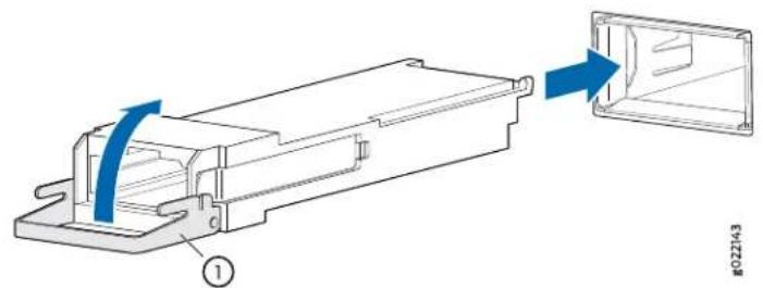
natural_image
Mechanical assembly diagram showing a component being extruded into a housing (no text or symbols present)1— Ejector lever
Removing a QSFP28 Transceiver
28-Gbps quad small form-factor pluggable (QSFP28) are transceivers that can be removed from the device. QSFP28 transceivers are hot-insertable and hot-removable. Removing a QSFP28 transceiver does not interrupt the device functioning, but the removed QSFP28 transceiver no longer receives or transmits data.
Figure 43: 28-Gbps Quad Small Form-Factor Pluggable (QSFP28)

To remove a QSFP28 transceiver (see Figure 43 on page 108):
- Place an electrostatic bag or antistatic mat on a flat, stable surface to receive the QSFP28 transceiver. Have ready a rubber safety cap for the QSFP28 transceiver and the cable.
- Attach an electrostatic discharge (ESD) grounding strap to your bare wrist, and connect the strap to one of the ESD points on the chassis.
- Label the cable connected to the QSFP28 transceiver so that you can later reconnect it to the correct QSFP28 transceiver.
- Disconnect the cable from the QSFP28 transceiver. Immediately cover the transceiver and the end of the cable with a rubber safety cap.

WARNING: Do not look directly into a fiber-optic transceiver or into the ends of fiber-optic cables. Fiber-optic transceivers and fiber-optic cable connected to a transceiver emit laser light that can damage your eyes.

CAUTION: Do not leave a fiber-optic transceiver uncovered except when inserting or removing cable. The safety cap keeps the port clean and prevents accidental exposure to laser light.
- Arrange the cable in the cable management system to prevent it from dislodging or developing stress points. Secure the cable so that it is not supporting its own weight as it hangs to the floor. Place excess cable out of the way in a neatly coiled loop in the cable management system. Placing fasteners on the loop helps to maintain its shape.

CAUTION: Avoid bending fiber-optic cable beyond its minimum bend radius. An arc smaller than a few inches in diameter can damage the cable and cause problems that are difficult to diagnose.
- Pull the transceiver's rubber handle straight back. The locking pins on the transceiver automatically release. Place the transceiver on the antistatic mat or in the electrostatic bag.
Installing a QSFP28 Transceiver
To install a replacement QSFP28:
-
Attach an electrostatic discharge (ESD) grounding strap to your bare wrist, and connect the strap to one of the ESD points on the chassis.
-
Verify that a rubber safety cap covers the QSFP28 transceiver, installing one if necessary.
-
Orient the QSFP28 over the port so that the QSFP28 connector faces the appropriate direction.
-
Slide the QSFP28 into the slot until the locking pins lock in place. If there is resistance, remove the QSFP28 and flip it so that the connector faces the other direction.
-
Remove the rubber safety cap from the transceiver and the end of the cable, and insert the cable into the transceiver.

WARNING: Do not look directly into a fiber-optic transceiver or into the ends of fiber-optic cables. Fiber-optic transceivers and fiber-optic cable connected to a transceiver emit laser light that can damage your eyes.

CAUTION: Do not leave a fiber-optic transceiver uncovered except when inserting or removing cable. The safety cap keeps the port clean and prevents accidental exposure to laser light.
- Arrange the cable in the cable management system to prevent the cable from dislodging or developing stress points. Secure the cable so that it is not supporting its own weight as it hangs to the floor. Place excess cable out of the way in a neatly coil loop in the cable management system. Placing fasteners on the loop helps to maintain its shape.

CAUTION: Do not let fiber-optic cable hang free from the connector. Do not allow fastened loops of cable to dangle, which stresses the cable at the fastening point.

CAUTION: Avoid bending fiber-optic cable beyond its minimum bend radius. An arc smaller than a few inches in diameter can damage the cable and cause problems that are difficult to diagnose.
- Verify that the status LEDs on the indicate that the QSFP28 is functioning correctly.
Disconnecting a Fiber-Optic Cable from the ACX6360
The ACX6360 has optical transceivers to which you can connect fiber-optic cables.
Before you disconnect a fiber-optic cable from an ACX6360, ensure that you have taken the necessary precautions for safe handling of lasers (see "Radiation from Open Port Apertures Warning" on page 145 and "Laser and LED Safety Guidelines and Warnings" on page 143).
Ensure that you have the following parts and tools available:
- Rubber safety cap to cover the transceiver
- Rubber safety cap to cover the fiber-optic cable connector
To disconnect a fiber-optic cable from an optical transceiver installed in the ACX6360:
- (Recommended) Disable the port in which the transceiver is installed by including the disable statement at the [edit interfaces] hierarchy level for the specific interface:
[edit interfaces]
set Interface-name disable

WARNING: Do not look directly into a fiber-optic transceiver or into the ends of fiber-optic cables. Fiber-optic transceivers and fiber-optic cables connected to transceivers emit laser light that can damage your eyes.

WARNING: Do not stare into the laser beam or view it directly with optical instruments even if the interface has been disabled.
-
Carefully unplug the fiber-optic cable connector from the transceiver.
-
Cover the transceiver with a rubber safety cap.

WARNING: Do not leave a fiber-optic transceiver uncovered except when inserting or removing a cable. The rubber safety cap keeps the port clean and prevents accidental exposure to laser light.
- Cover the fiber-optic cable connector with the rubber safety cap.
Connecting a Fiber-Optic Cable to the ACX6360
The ACX6360 has optical transceivers to which you can connect fiber-optic cables.
Before you connect a fiber-optic cable to an ACX6360, ensure that you have taken the necessary precautions for safe handling of lasers (see "Radiation from Open Port Apertures Warning" on page 145 and "Laser and LED Safety Guidelines and Warnings" on page 143).
To connect a fiber-optic cable to an optical transceiver installed in the ACX6360:

WARNING: Do not look directly into a fiber-optic transceiver or into the ends of fiber-optic cables. Fiber-optic transceiversandfiber-opticcablesconnected to transceivers emit laser light that can damage your eyes.

WARNING: Do not stare into the laser beam or view it directly with optical instruments even if the interface has been disabled.
- If the fiber-optic cable connector is covered by a rubber safety cap, remove the cap. Save the cap.
- If the optical transceiver is covered by a rubber safety cap, remove the cap. Save the cap.
- Insert the cable connector into the optical transceiver.
- Secure the cable so that it does not support its own weight. Place excess cable out of the way in a neatly coiled loop. Placing fasteners on a loop helps cables maintain their shape.

CAUTION: Do not bend fiber-optic cables beyond their minimum bend radius. Bending the cables beyond their minimum bend radius candamage the cables and cause problems that are difficult to diagnose.

CAUTION: Do not let fiber-optic cables hang free from the connector. Do not allow fastened loops of cables to dangle, which stresses the cables at the fastening point.
Maintaining Fiber-Optic Cables in an ACX6360
To maintain fiber-optic cables in an ACX6360:
- When you unplug fiber-optic cables from transceivers, place rubber safety caps over the transceivers and on the end of the cables.
-
Anchor fiber-optic cables to avoid stress on the connectors. When attaching a fiber-optic cable to a transceiver, be sure to secure the fiber-optic cable so that it does not support its own weight as it hangs to the floor. Never let a fiber-optic cable hang free from the connector.
-
Do not bend fiber-optic cables beyond their minimum bend radius. Bending the cables beyond their minimum bend radius can damage the cables and cause problems that are difficult to diagnose.
- Frequent plugging and unplugging of fiber-optic cables in and out of optical instruments can damage the instruments, which are expensive to repair. Attach a short fiber extension to the optical equipment. Any wear and tear due to frequent plugging and unplugging is then absorbed by the short fiber extension, which is easier and less expensive to replace than the instruments.
- Keep fiber-optic cable connections clean. Microdeposits of oil and dust in the canal of the transceiver or cable connector can cause loss of light, reduction in signal power, and possibly intermittent problems with the optical connection.
To clean the transceiver canal, use an appropriate fiber-cleaning device such as RIFOCS Fiber Optic Adaptor Cleaning Wands (part number 946). Follow the directions in the cleaning kit you use.
After cleaning the transceiver, make sure that the connector tip of the fiber-optic cable is clean. Use only an approved alcohol-free fiber-optic cable cleaning kit such as the Cletop-S® Fiber Cleaner. Follow the directions in the cleaning kit you use.
Related Documentation
Maintaining the SATA Solid State Drive in an ACX6360
- Removing a SATA Solid State Drive in an ACX6360 on page 114
• Installing a SATA Solid State Drive in an ACX6360 on page 115
Removing a SATA Solid State Drive in an ACX6360
The ACX6360 allows for two 50 GB serial advanced technology attachment (SATA) solid state drives (SSD) as a secondary boot drive or for log storage. The SATA SSD is a hot-insertable and hot-removable field-replaceable unit (FRU).
Before you remove an SATA SSD from the device, ensure that you understand how to prevent ESD damage. See "Prevention of Electrostatic Discharge Damage" on page 153.
Ensure that you have the following parts and tools available to remove an SATA SSD from an ACX6360:
• Electrostatic discharge (ESD) grounding strap
• Phillips (+) screwdriver, number 1
- An electrostatic bag or antistatic mat
To remove a SATA SSD in an ACX6360:
- Place an electrostatic bag or antistatic mat on a flat, stable surface to receive the SATA SSD.
- Attach an electrostatic discharge (ESD) grounding strap to your bare wrist, and connect the strap to one of the ESD points on the chassis.
- Remove the eight captive screws securing the SSD cover plate by using the Phillips (+) screwdriver, number 1. The SSD cover plate is located on the top of the chassis (see Figure 44 on page 114.
Figure 44: Removing the SATA SSD Cover Plate

natural_image
Technical line drawing of a server rack with multiple ports and ventilation grilles (no text or symbols)- Remove the single screw holding the SATA SSD in place and slide the drive out of the plug (see Figure 45 on page 115).
Figure 45: Removing the SATA SSD

natural_image
Technical diagram of an electronic device housing with internal components and mounting holes (no text or symbols)-
Place the SATA SSD in an electrostatic bag or on an antistatic mat.
-
Place the SSD cover plate back on the chassis and tighten the eight captive screws securing the SSD cover plate.
Installing a SATA Solid State Drive in an ACX6360
Before you install an SATA SSD in the device, ensure that you understand how to prevent ESD damage. See "Prevention of Electrostatic Discharge Damage" on page 153.
Ensure that you have the following parts and tools available to install an SATA SSD in the ACX6360:
• Electrostatic discharge (ESD) grounding strap
• Phillips (+) screwdriver, number 1
- An electrostatic bag or antistatic mat
To install a SATA SSD in an ACX6360:
-
Attach anelectrostaticdischarge (ESD) grounding strap to your bare wrist, and connect the strap to one of the ESD points on the chassis.
-
If not already removed, remove the eight captive screws securing the SSD cover plate by using the Phillips (+) screwdriver, number 1. The SSD cover plate is located on the top of the chassis (see Figure 46 on page 115.
Figure 46: Removing the SATA SSD Cover Plate

natural_image
Technical line drawing of a server rack with multiple ports and mounting points (no text or symbols)- Slide the drive into the SSD plug and tighten the single screw holding the SATA SSD. (see Figure 47 on page 116).
Figure 47: Installing the SATA SSD

natural_image
Technical diagram of an electronic device housing with internal components and mounting holes (no text or symbols)- Place the SSD cover plate back on the chassis and tighten the eight captive screws securing the SSD cover plate.
Related Documentation
Uninstalling the ACX6360
- Removing an ACX6360 from a Rack or Cabinet on page 116
Removing an ACX6360 from a Rack or Cabinet
If you need to relocate an installed ACX6360, use the procedure described in this topic. (The remainder of this topic uses "rack" to mean "rack or cabinet.")

NOTE: When you remove multiple devices from a rack, remove the device at the top of the rack first and proceed to remove the rest of the devices from top to bottom.
Before removing an ACX6360 from a rack:
- Ensure that the rack is stable and secured to the building.
- Ensure that there is enough space to place the removed ACX6360 in its new location and along the path to the new location.
- Read "General Safety Guidelines and Warnings" on page 132 and "ACX6360 Installation Safety Guidelines" on page 64.
-
Use the power off sequence described in "Powering Off the ACX6360" on page 93 to safely power off the device..
-
Disconnect the power cords.
- Ensure that you have disconnected any cables or wires attached to the ACX6360 (see "Disconnecting a Fiber-Optic Cable from the ACX6360" on page 110).
Ensure that you have the following parts and tools available:
- A Phillips (+) screwdriver, number 2 or number 3, depending on the size of your rack mounting screws, for removing the ACX6360 from the rack.
To remove an ACX6360 from a rack:
- Have one person support the weight of the switch while another person uses the screwdriver to remove the front mounting screws that attach the chassis mounting brackets to the rack.
- Remove the ACX6360 from the rack.
- Use the screwdriver to remove the mounting screws that attach the mounting blades attached to the rear of the rack.
- Place the removed screws and rear-mounting blades in a labeled bag. You will need them when you reinstall the chassis.
- Transport the ACX6360 to your desired new location.
See Also
Related • Unpacking and Mounting the ACX6360 on page 65 Documentation
CHAPTER 5
Troubleshooting Hardware
- Troubleshooting the ACX6360 on page 119
Troubleshooting the ACX6360
• ACX6360 Troubleshooting Resources Overview on page 119
• ACX6360 Alarm Messages Overview on page 120
- Chassis Alarm Messages on the ACX6360 on page 120
ACX6360 Troubleshooting Resources Overview
To troubleshoot an ACX6360, you use the Junos OS CLI, alarms, and LEDs on the network ports, management panel, and components.
- LEDs—When the Routing Engine detects an alarm condition, it lights the red or yellow alarm LED on the management panel as appropriate. In addition, you can also use component LEDs and network port LEDs to troubleshoot the ACX6360. For more information, see the following topics:
• ACX6360 Chassis Status LEDs on page 26
• ACX6360 Management Port LEDs on page 27
• ACX6360 Network Port LEDs on page 28
• ACX6360 Fan Module LEDs on page 33
• ACX6360 AC Power Supply LEDs on page 35
• ACX6360 DC Power Supply LEDs on page 37
- CLI—The CLI is the primary tool for controlling and troubleshooting hardware, Junos OS, routing protocols, and network connectivity. CLI commands display information from routing tables, information specific to routing protocols, and information about network connectivity derived from the ping and traceroute utilities. For information about using the CLI to troubleshoot Junos OS, see the appropriate Junos OS configuration guide.
- JTAC—If you need assistance during troubleshooting, you can contact the Juniper Networks Technical Assistance Center (JTAC) by using the Web or by telephone. If you encounter software problems, or problems with hardware components not discussed here, contact JTAC.
ACX6360 Alarm Messages Overview
When the Routing Engine detects an alarm condition, it lights the red or yellow alarm LED on the management panel as appropriate. To view a more detailed description of the alarm cause, issue the show chassis alarms CLI command:
user@host> show chassis alarms
| 2 alarms currently active | |||
| Alarm time | Class | Description | |
| 2017-01-23 | 02:39:29 | PST Major | PEM 3 Not Present |
| 2017-01-23 | 02:39:29 | PST Major | PEM 1 Not Present |
Chassis Alarm Messages on the ACX6360
Chassis alarms indicate a failure on the device or one of its components. Chassis alarms are preset and cannot be modified.
Chassis alarms on ACX6360 routers have two severity levels:
- Major (red)—Indicates a critical situation on the device that has resulted from one of the conditions described in Table 35 on page 121. A red alarm condition requires immediate action.
- Minor (yellow or amber)—Indicates a noncritical condition on the device that, if left unchecked, might cause an interruption in service or degradation in performance. A yellow alarm condition requires monitoring or maintenance.
Table 35 on page 121 describes the chassis alarm messages on the ACX6360.
Table 35: ACX6360 Chassis Alarm Messages
| Recommended ActionCLI MessageA | |||
| Fan FailureMajor (red)Fans | Replace the fan module and report the failure to customer support. | ||
| Fan I2C Failure | Check the system log for one of the following messages and report the error message to customer support:CM ENV Monitor: Get fan speed failed.fan-number is NOT spinning @ correct speed, where fan-number can be 1, 2, 3, 4, or 5. | ||
| Fan fan-number Not Spinning | Remove and check the fan module for obstructions, and then reinsert the fan module. If the problem persists, replace the fan module. | ||
| Fan/Blower AbsentMinor (yellow) | Check the system log for the message fan-number Absent, where fan-number can be 1, 2, 3, 4, or 5.Install the fan module. |
Table 35: ACX6360 Chassis Alarm Messages (continued)
| Recommended ActionCLI MessageA | ||
| Major (red)Power PEM pem-number Airflow not matching Chassis Airflow | Replace the power supply with a power supply that supports the same airflow direction as the chassis. | |
| PEM pem-number I2C Failure | Check the system log for one of the following messages and report the error message to customer support:I2C Read failed for device number, where number may be from 123 to 125.PS number: Transitioning from online to offline, where power supply (PS) number may be 1 or 2. | |
| PEM pem-number is not powered | Check the power cord connection and reconnect, if necessary. | |
| PEM pem-number is not supported | Replace the power supply with a supported power supply. | |
| PEM pem-number Not OK | Indicates a problem with the incoming AC power or outgoing DC power. Report the error to customer support. | |
| PEM pem-number AbsentMinor (yellow) | A power supply is not installed. Install a supported power supply in the appropriate slot. | |
| PEM pem-number Power Supply Type Mismatch | Check if there is a mix of AC and DC power supplies in the same chassis. Reboot the device with only AC or only DC power supplies. | |
| Replace the removed power supply.PEM pem-number R |
Table 35: ACX6360 Chassis Alarm Messages (continued)
| Recommended ActionCLI MessageA | |||
| sensors | sensor-location Temp Sensor FailMajor (Crd)Temp sensor system log for the following message and report it to customer support:Temp sensor sensor-number failed, where sensor-number ranges from 1 through 10. | ||
| sensor-location Temp Sensor Too Hot | Check environmental conditions and alarms on other devices. Ensure that environmental factors (such as hot air blowing around the equipment) do not affect the temperature sensor. If the condition persists, the device might shut down. | ||
| sensor-location Temp Sensor Too Warm | Timoinfeylation only. Check environmental conditions and alarms on other devices. Ensure that environmental factors (such as hot air blowing around the equipment) do not affect the temperature sensor. | ||
| RE RE number /var partition is fullMajocleed)Routing Engine file storage space on the device. For more information, see request system storage cleanup. | |||
| RE RE number /var partition usage is HighMinup (Welosystem file storage space on the device. For more information, see request system storage cleanup. | |||
| Ethernet Interface | Management Ethernet 1 Link DownMajorCheck)Nettreatmentcable is connected to the management Ethernet interface, or whether the cable is defective. Replace the cable, if required.If you are unable to resolve the problem, open a support case by using the Case Manager link athttps://www.juniper.net/support/ or call 1-888-314-5822 (tollfree, US or 1-408-745-9500 (from outside the United States). | ||
See Also
Related .ACX6360 Management Panel on page 30
•Definitions of Safety Warning Levels on page 133
alarm
- Contacting Customer Support on page 125
CHAPTER 6
Contacting Customer Support and Returning the Chassis or Components
- Returning the ACX6360 Chassis or Components on page 125
Returning the ACX6360 Chassis or Components
- Contacting Customer Support on page 125
- Locating the Serial Number on an ACX6360 Chassis or Component on page 126
- Returning a Hardware Component to Juniper Networks, Inc. on page 127
• Guidelines for Packing Hardware Components for Shipment on page 128 - Packing an ACX6360 Chassis or Component for Shipping on page 128
Contacting Customer Support
You can contact Juniper Networks Technical Assistance Center (JTAC) 24 hours a day, 7 days a week in one of the following ways:
- On the Web, using the Service Request Manager link at:
https://support.juniper.net/support/
- By telephone:
• From the US and Canada: 1-888-314-JTAC
• From all other locations: 1-408-745-9500

NOTE: If contacting JTACby telephone, enter your12-digitservice request number followed by the pound (#) key if this is an existing case, or press the star (*) key to be routed to the next available support engineer.
When requesting support from JTAC by telephone, be prepared to provide the following information:
-
Your existing service request number, if you have one
• Details of the failure or problem -
Type of activity being performed on the device when the problem occurred
- Configuration data displayed by one or more show commands
- Your name, organization name, telephone number, fax number, and shipping address
The support representative validates your request and issues an RMA number for return of the component.
Locating the Serial Number on an ACX6360 Chassis or Component
If you are returning an ACX6360 or an ACX6360 field-replaceable unit (FRU) to Juniper Networks for repair or replacement, you must locate the serial number of the router or FRU. You must provide the serial number to the Juniper Networks Technical Assistance Center (JTAC) when you contact them to obtain a Return Materials Authorization (RMA). See "Returning a Hardware Component to Juniper Networks, Inc." on page 127.
If the ACX6360 is operational and you can access the command-line interface (CLI), you can list serial numbers for the router and some components with a CLI command. If you do not have access to the CLI or if the serial number for the FRU does not appear in the command output, you can locate the serial number ID label on the router or FRU.

NOTE: If you want to find the serial number ID label on a component, you need to remove the component from the chassis, for which you must have the required parts and tools available.

NOTE: You must remove the fan module to read the serial number from the serial number ID label. The fan module serial number cannot be viewed through the CLI.
- Listing the Chassis and Component Details by Using the CLI on page 126
- Locating the Chassis Serial Number ID Label on an ACX6360 on page 127
- Locating the Serial Number ID Labels on FRU Components on page 127
Listing the Chassis and Component Details by Using the CLI
To list the ACX6360 and components and their serial numbers, use the show chassis hardware CLI operational mode command.
user@host> show chassis hardware
| Hardware inventory: | ||||
| Item | Version | Part number | Serial number | Description |
| Chassis | 00000 | JNP6360 [ACX6360-OR] | ||
| Pseudo CB 0 | ||||
| Routing Engine 0 | BUILTIN | BUILTIN | RE-ACX6360-OR | |
| FPC 0 | REV 11 | 750-075975 | BCAA7054 | JNP6360-CHAS |
| CPU | REV 11 | 711-068842 | BCAD4406 | JNP10001-CPU |
| PIC 0 | BUILTIN | BUILTIN | 20X100G | |
| Xcvr 0 | REV 01 | 740-061405 | 1ACQ112301M | QSFP-100GBASE-SR4 |
| Xcvr 7 | REV 01 | 740-058732 | 1FCQA14900L | QSFP-100GBASE-LR4 |
| Xcvr 15 | REV 01 | 740-046565 | QE413794 | QSFP+-40G-SR4 |
| Xcvr 16 | REV 01 | 740-046565 | QF051229 | QSFP+-40G-SR4 |
| Xcvr 18 | REV 01 | 740-046565 | QF3403FN | QSFP+-40G-SR4 |
| Xcvr 19 | REV 01 | 740-046565 | QE414381 | QSFP+-40G-SR4 |
| PIC 1 | REV 03 | 711-072388 | BCAD9508 | 8x200GE DWDM CFP2-DCO |
| Xcvr 0 | REV 01 | 740-075974 | 174653205 | CFP2-DCO tunable DWDM |
| Xcvr 7 | REV | 740-075974 | 170255154 | CFP2-DCO tunable DWDM |
| Power Supply 0 | REV 04 | 740-053352 | 1GD17210533 | JPSU-850W-AC-AFO |
| Power Supply 1 | REV 04 | 740-053352 | 1GD17210725 | JPSU-850W-AC-AFO |
| Fan Tray 0 | ACX6360-OR Fan Controller | |||
| 0, Front to Back Airflow - AFO | ||||
| Fan Tray 1 | ACX6360-OR Fan Controller | |||
| 1, Front to Back Airflow - AFO | ||||
| Fan Tray 2 | ACX6360-OR Fan Controller | |||
| 2, Front to Back Airflow - AFO | ||||
| Fan Tray 3 | ACX6360-OR Fan Controller | |||
| 3, Front to Back Airflow - AFO | ||||
| Fan Tray 4 | ACX6360-OR Fan Controller | |||
| 4, Front to Back Airflow - AFO | ||||
Locating the Chassis Serial Number ID Label on an ACX6360
The serial number ID label is located on a label on the top cover.
Locating the Serial Number ID Labels on FRU Components
For each FRU, you must remove the FRU from the chassis to see the FRU's serial number ID label.
- AC power supply—The serial number ID label is on the top of the AC power supply.
- DC power supply—The serial number ID label is on the top of the DC power supply.
- Fan module—The serial number ID label is on the top of the fan module.
See Also
Returning a Hardware Component to Juniper Networks, Inc.
If a hardware component fails, please contact Juniper Networks, Inc. to obtain a Return Material Authorization (RMA) number. This number is used to track the returned material at the factory and to return repaired or new components to the customer as needed.

NOTE: Do not return any component to Juniper Networks, Inc. unless you have first obtained an RMA number. Juniper Networks, Inc. reserves the right to refuseshipments that do not have an RMA. Refused shipments are returned to the customer by collect freight.
For more information about return and repair policies, see the customer support webpage at https://support.juniper.net/support/.
For product problems or technical support issues, contact the Juniper Networks Technical Assistance Center (JTAC) by using the Service Request Manager link at
https://support.juniper.net/support/ or at 1-888-314-JTAC (within the United States) or 1-408-745-9500 (from outside the United States).
To return a defective hardware component:
- Determine the part number and serial number of the defective component.
- Obtain an RMA number from the Juniper Networks Technical Assistance Center (JTAC). You can send e-mail or telephone as described above.
- Provide the following information in your e-mail message or during the telephone call:
- Part number and serial number of component
- Your name, organization name, telephone number, and fax number
• Description of the failure - The support representative validates your request and issues an RMA number for return of the component.
- Pack the component for shipment.
Guidelines for Packing Hardware Components for Shipment
To pack and ship individual components:
- When you return components, make sure that they are adequately protected with packing materials and packed so that the pieces are prevented from moving around inside the carton.
- Use the original shipping materials if they are available.
- Place individual components in antistatic bags.
- Write the RMA number on the exterior of the box to ensure proper tracking.

CAUTION: Do not stack any of the hardware components.
Packing an ACX6360 Chassis or Component for Shipping
If you are returning an ACX6360 or component to Juniper Networks for repair or replacement, pack the item as described in this topic.
Before you pack an ACX6360 or component:
- Ensure that you have taken the necessary precautions to prevent electrostatic discharge (ESD) damage. See “Prevention of Electrostatic Discharge Damage” on page 153.
- Retrieve the original shipping carton and packing materials. Contact your JTAC representative if you do not have these materials, to learn about approved packing materials (see “Contacting Customer Support” on page 125).
Ensure that you have the following parts and tools available:
- ESD grounding strap.
- Antistatic bag, one for each component.
- If you are returning the chassis, an appropriate screwdriver for the mounting screws used on your rack or cabinet.
- Packing an ACX6360 for Shipping on page 129
- Packing ACX6360 Components for Shipping on page 130
Packing an ACX6360 for Shipping
To pack an ACX6360 for shipping:
- Power off the ACX6360 and remove the AC power cords or DC power cables. See "Powering Off the ACX6360" on page 93.
- Remove the cables that connect the ACX6360 to all external devices. See "Disconnecting a Fiber-Optic Cable from the ACX6360" on page 110.
- Remove all field-replaceable units (FRUs) from the router. See:
- Removing a Fan Module from the ACX6360 on page 97
- Removing a Power Supply from the ACX6360 on page 100
- Remove the ACX6360 from the rack or cabinet. See "Uninstalling the ACX6360" on page 116.
- Place the ACX6360 in an antistatic bag.
- Place the ACX6360 in the shipping carton.
- Place the packing foam on top of and around the ACX6360.
- If you are returning accessories or FRUs with the ACX6360, pack them as instructed in "Packing ACX6360 Components for Shipping" on page 130.
- Close the top of the cardboard shipping box and seal it with packing tape.
- Write the return materials authorization (RMA) number on the exterior of the box to ensure proper tracking. See "Returning a Hardware Component to Juniper Networks, Inc." on page 127 for instructions on obtaining an RMA number.
Packing ACX6360 Components for Shipping

CAUTION: DonotstackACX6360components.Returnindividualcomponents in separate boxes if they do not fit together on one level in the shipping box.
To pack and ship ACX6360 components:
- Place individual FRUs in antistatic bags.
- Ensure that the components are adequately protected with packing materials and packed so that the pieces are prevented from moving around inside the carton.
- Close the top of the cardboard shipping box and seal it with packing tape.
- Write the RMA number on the exterior of the box to ensure proper tracking. See "Returning a Hardware Component to Juniper Networks, Inc." on page 127 for instructions on obtaining an RMA number.
CHAPTER 7
Safety and Compliance Information
- General Safety Guidelines and Warnings on page 132
- Definitions of Safety Warning Levels on page 133
• Qualified Personnel Warning on page 134 - Warning Statement for Norway and Sweden on page 135
• Fire Safety Requirements on page 135
• Installation Instructions Warning on page 136 - Chassis and Component Lifting Guidelines on page 137
- Restricted Access Warning on page 137
- Ramp Warning on page 138
- Rack-Mounting and Cabinet-Mounting Warnings on page 139
• Grounded Equipment Warning on page 143 - Laser and LED Safety Guidelines and Warnings on page 143
- Radiation from Open Port Apertures Warning on page 145
- Maintenance and Operational Safety Guidelines and Warnings on page 146
- General Electrical Safety Guidelines and Warnings on page 151
• Action to Take After an Electrical Accident on page 152
• Prevention of Electrostatic Discharge Damage on page 153
• AC Power Electrical Safety Guidelines on page 154
• AC Power Disconnection Warning on page 155
• DC Power Electrical Safety Guidelines on page 155
• DC Power Copper Conductors Warning on page 156
• DC Power Disconnection Warning on page 156
• DC Power Grounding Requirements and Warning on page 158
• DC Power Wiring Sequence Warning on page 159
• DC Power Wiring Terminations Warning on page 160 - Multiple Power Supplies Disconnection Warning on page 161
• TN Power Warning on page 162
• ACX6360 Agency Approvals and Compliance Statements on page 163
General Safety Guidelines and Warnings
The following guidelines help ensure your safety and protect the device from damage. The list of guidelines might not address all potentially hazardous situations in your working environment, so be alert and exercise good judgment at all times.
- Perform only the procedures explicitly described in the hardware documentation for this device. Make sure that only authorized service personnel perform other system services.
- Keep the area around the device clear and free from dust before, during, and after installation.
- Keep tools away from areas where people could trip over them while walking.
- Do not wear loose clothing or jewelry, such as rings, bracelets, or chains, which could become caught in the device.
- Wear safety glasses if you are working under any conditions that could be hazardous to your eyes.
- Do not perform any actions that create a potential hazard to people or make the equipment unsafe.
- Never attempt to lift an object that is too heavy for one person to handle.
- Never install or manipulate wiring during electrical storms.
- Never install electrical jacks in wet locations unless the jacks are specifically designed for wet environments.
- Operate the device only when it is properly grounded.
- Ensure that the separate protective earthing terminal provided on this device is permanently connected to earth.
- Replace fuses only with fuses of the same type and rating.
- Do not open or remove chassis covers or sheet-metal parts unless instructions are provided in the hardware documentation for this device. Such an action could cause severe electrical shock.
- Do not push or force any objects through any opening in the chassis frame. Such an action could result in electrical shock or fire.
- Avoid spilling liquid onto the chassis or onto any device component. Such an action could cause electrical shock or damage the device.
- Avoid touching uninsulated electrical wires or terminals that have not been disconnected from their power source. Such an action could cause electrical shock.
- Some parts of the chassis, including AC and DC power supply surfaces, power supply unit handles, SFB card handles, and fan tray handles might become hot. The following label provides the warning of the hot surfaces on the chassis:

- Always ensure that all modules, power supplies, and cover panels are fully inserted and that the installation screws are fully tightened.
Definitions of Safety Warning Levels
The documentation uses the following levels of safety warnings (there are two Warning formats):

NOTE: You might find this information helpful in a particular situation, or you might overlook this important information if it was not highlighted in a Note.

CAUTION: You need to observe the specified guidelines to prevent minor injury or discomfort to you or severe damage to the device.

WARNING: This symbol alerts you to the risk of personal injury from a laser.

WARNING: Thissymbolmeans danger. You are in a situation that could cause bodily injury. Before you work on any equipment, be aware of the hazards involved with electrical circuitry and be familiar with standard practices for preventing accidents.
Qualified Personnel Warning

WARNING: Only trained and qualified personnel should install or replace the device.
Warning Statement for Norway and Sweden

WARNING: The equipment must be connected to an earthed mains socket-outlet.
Fire Safety Requirements
In the event of a fire emergency, the safety of people is the primary concern. You should establish procedures for protecting people in the event of a fire emergency, provide safety training, and properly provision fire-control equipment and fire extinguishers.
In addition, you should establish procedures to protect your equipment in the event of a fire emergency. Juniper Networks products should be installed in an environment suitable for electronic equipment. We recommend that fire suppression equipment be available in the event of a fire in the vicinity of the equipment and that all local fire, safety, and electrical codes and ordinances be observed when you install and operate your equipment.
Fire Suppression
In the event of an electrical hazard or an electrical fire, you should first turn power off to the equipment at the source. Then use a Type C fire extinguisher, which uses noncorrosive fire retardants, to extinguish the fire.
Fire Suppression Equipment
Type C fire extinguishers, which use noncorrosive fire retardants such as carbon dioxide and Halotron™, are most effective for suppressing electrical fires. Type C fire extinguishers displace oxygen from the point of combustion to eliminate the fire. For extinguishing fire on or around equipment that draws air from the environment for cooling, you should use
this type of inert oxygen displacement extinguisher instead of an extinguisher that leaves residues on equipment.
Do not use multipurpose Type ABC chemical fire extinguishers (dry chemical fire extinguishers). The primary ingredient in these fire extinguishers is monoammonium phosphate, which is very sticky and difficult to clean. In addition, in the presence of minute amounts of moisture, monoammonium phosphate can become highly corrosive and corrodes most metals.
Any equipment in a room in which a chemical fire extinguisher has been discharged is subject to premature failure and unreliable operation. The equipment is considered to be irreparably damaged.

NOTE: Tokeep warranties effective, donotusea dry chemicalfire extinguisher to control a fire at or near a Juniper Networks device. If a dry chemical fire extinguisher is used, the unit is no longer eligible for coverage under a service agreement.
We recommend that you dispose of any irreparably damaged equipment in an environmentally responsible manner.
Installation Instructions Warning

WARNING: Read the installation instructions before you connect the device to a power source.
Chassis and Component Lifting Guidelines
The Ground Truth image displays a single, solid horizontal line. According to Rule 2 (UNDERSCORE & LINE RULES), this is a stylistic or background line, not a placeholder underscore. Therefore, the OCR result must ignore it and output nothing or only meaningful text. The provided OCR content is "____", which consists of four underscores. This is an incorrect interpretation of the line as a fill-in-the-blank placeholder, violating the rule that stylistic lines must be ignored. The OCR has hallucinated underscores where none should exist based on the GT's visual context. Hence, the OCR result is inconsistent with the Ground Truth.
• Before moving the device to a
and clearance requirements.
- Before moving the device to a site, ensure that the site meets the power, environmental,
and clearance requirements.
- Before lifting or moving the device, disconnect all external cables and wires.
- As when lifting any heavy object, ensure that most of the weight is borne by your legs rather than your back. Keep your knees bent and your back relatively straight. Do not twist your body as you lift. Balance the load evenly and be sure that your footing is firm
- Use the following lifting guidelines to lift devices and components:
• Up to 39.7 lb (18 kg): One person.
• 39.7 lb (18 kg) to 70.5 lb (32 kg): Two or more people.
- 70.5 lb (32 kg) to 121.2 lb (55 kg): Three or more people.
- Above 121.2 lbs (55 kg): Material handling systems (such as levers, slings, lifts and so on) must be used. When this is not practical, specially trained persons or systems must be used (riggers or movers).
Restricted Access Warning

WARNING: This unit is intended for installation in restricted access areas. A restricted accessareaisanareatowhichaccesscan be gainedonly by service personnel through the use of a special tool, lock and key, or other means of security, and which is controlled by the authority responsible for the location.
WARNING: When installing the device, do not use a ramp inclined at more than 10 degrees.
Rack-Mounting and Cabinet-Mounting Warnings
Ensure that the rack or cabinet in which the device is installed is evenly and securely supported. Uneven mechanical loading could lead to a hazardous condition.

WARNING: To prevent bodily injury when mounting or servicing the device in a rack, take the following precautions to ensure that the system remains stable. The following directives help maintain your safety:
- The device must be installed in a rack that is secured to the building structure.
- The device should be mounted at the bottom of the rack if it is the only unit in the rack.
- When mounting the device on a partially filled rack, load the rack from the bottom to the top with the heaviest component at the bottom of the rack.
- If the rack is provided with stabilizing equipment, install the stabilizers before mounting or servicing the device in the rack.
Grounded Equipment Warning

WARNING: The device is intended to be grounded. During normal use, ensure that you have connected earth ground to the chassis.
Laser and LED Safety Guidelines and Warnings
Juniper Networks devices are equipped with laser transmitters, which are considered a Class 1 Laser Product by the U.S. Food and Drug Administration and are evaluated as a Class 1 Laser Product per EN 60825-1 requirements.
Observe the following guidelines and warnings:
• General Laser Safety Guidelines on page 144
• Class 1 Laser Product Warning on page 144
• Class 1 LED Product Warning on page 144
• Laser Beam Warning on page 145
General Laser Safety Guidelines
When working around ports that support optical transceivers, observe the following safety guidelines to prevent eye injury:
- Do not look into unterminated ports or at fibers that connect to unknown sources.
- Do not examine unterminated optical ports with optical instruments.
- Avoid direct exposure to the beam.

WARNING: Unterminated optical connectors can emit invisible laser radiation. The lens in the human eye focuses all the laser power on the retina, so focusing the eye directly on a laser source—even a low-power laser—could permanently damage the eye.
Class 1 Laser Product Warning

WARNING: Class 1 laser product.
Waarschuwing Klasse-1 laser produkt.
Class 1 LED Product Warning

WARNING: Class 1 LED product.
WARNING: Do not stare into the laser beam or view it directly with optical instruments.
Radiation from Open Port Apertures Warning

WARNING: Because invisible radiation might be emitted from the aperture of the port when no fiber cable is connected, avoid exposure to radiation and do not stare into open apertures.
Maintenance and Operational Safety Guidelines and Warnings
While performing the maintenance activities for devices, observe the following guidelines and warnings:
• Battery Handling Warning on page 147
• Jewelry Removal Warning on page 148
• Lightning Activity Warning on page 149
- Operating Temperature Warning on page 149
• Product Disposal Warning on page 151
Battery Handling Warning

WARNING: Replacing a battery incorrectly might result in an explosion. Replace a battery only with the same or equivalent type recommended by the manufacturer. Dispose of used batteries according to the manufacturer's instructions.
Jewelry Removal Warning

WARNING: Before working on equipment that is connected to power lines, remove jewelry, including rings, necklaces, and watches. Metal objects heat up when connected to power and ground and can cause serious burns or can be welded to the terminals.
WARNING: Do not work on the systemor connectordisconnect cables during periods of lightning activity.
Operating Temperature Warning

WARNING: To prevent the device from overheating, do not operate it in an area that exceeds the maximum recommended ambient temperature. To
prevent airflow restriction, allow at least 6 in. (15.2 cm) of clearance around the ventilation openings.
Product Disposal Warning

WARNING: Disposal of this device must be handled according to all national laws and regulations.
General Electrical Safety Guidelines and Warnings

WARNING: Certain ports on the device are designed for use as intrabuilding (within-the-building) interfaces only (Type 2 or Type 4 ports as described in GR-1089-CORE) and require isolation from the exposed outside plant (OSP) cabling. To comply with NEBS requirements and protect against lightning surges and commercial power disturbances, the intrabuilding ports must not be metallically connected to interfaces that connect to the OSP or its wiring. The intrabuilding ports on the device are suitable for connection to intrabuilding or unexposed wiring or cabling only. The addition of primary protectors is not sufficient protection for connecting these interfaces metallically to OSP wiring.

CAUTION: Before removing or installing components of a device, connect an electrostatic discharge (ESD) grounding strap to an ESD point and wrap and fasten the other end of the strap around your bare wrist. Failure to use an ESD grounding strap could result in damage to the device.
- Install the device in compliance with the following local, national, and international electrical codes:
- United States—National Fire Protection Association (NFPA 70), United States National Electrical Code.
- Other countries—International Electromechanical Commission (IEC) 60364, Part 1 through Part 7.
- Evaluated to the TN power system.
• Canada—Canadian Electrical Code, Part 1, CSA C22.1. - Locate the emergency power-off switch for the room in which you are working so that if an electrical accident occurs, you can quickly turn off the power.
- Make sure that grounding surfaces are cleaned and brought to a bright finish before grounding connections are made.
- Do not work alone if potentially hazardous conditions exist anywhere in your workspace.
- Never assume that power is disconnected from a circuit. Always check the circuit before starting to work.
- Carefully look for possible hazards in your work area, such as moist floors, ungrounded power extension cords, and missing safety grounds.
- Operate the device within marked electrical ratings and product usage instructions.
- To ensure that the device and peripheral equipment function safely and correctly, use the cables and connectors specified for the attached peripheral equipment, and make certain they are in good condition.
You can remove and replace many device components without powering off or disconnecting power to the device, as detailed elsewhere in the hardware documentation for this device. Never install equipment that appears to be damaged.
Action to Take After an Electrical Accident
If an electrical accident results in an injury, take the following actions in this order:
- Use caution. Be aware of potentially hazardous conditions that could cause further injury.
- Disconnect power from the device.
- If possible, send another person to get medical aid. Otherwise, assess the condition of the victim, then call for help.
Prevention of Electrostatic Discharge Damage
Device components that are shipped in antistatic bags are sensitive to damage from static electricity. Some components can be impaired by voltages as low as 30 V. You can easily generate potentially damaging static voltages whenever you handle plastic or foam packing material or if you move components across plastic or carpets. Observe the following guidelines to minimize the potential for electrostatic discharge (ESD) damage, which can cause intermittent or complete component failures:
• Always use an ESD wrist strap when you are handling components that are subject to ESD damage, and make sure that it is in direct contact with your skin.
If a grounding strap is not available, hold the component in its antistatic bag (see Figure 48 on page 153) in one hand and touch the exposed, bare metal of the device with the other hand immediately before inserting the component into the device.

WARNING: For safety, periodically check the resistance value of the ESD grounding strap. The measurement must be in the range 1 through 10 Mohms.
- When handling any component that is subject to ESD damage and that is removed from the device, make sure the equipment end of your ESD wrist strap is attached to the ESD point on the chassis.
If no grounding strap is available, touch the exposed,bare metal of the device to ground yourself before handling the component. - Avoid contact between the component that is subject to ESDdamage and your clothing. ESD voltages emitted from clothing can damage components.
- When removing or installing a component that is subject to ESD damage, always place it component-side up on an antistatic surface, in an antistatic card rack, or in an antistatic bag (see Figure 48 on page 153). If you are returning a component, place it in an antistatic bag before packing it.
Figure 48: Placing a Component into an Antistatic Bag
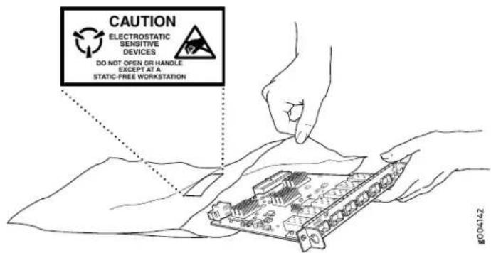

CAUTION: ANSI/TIA/EIA-568 cables such as Category 5e and Category 6 can get electrostatically charged. To dissipate this charge, always ground the cables to a suitable and safe earth ground before connecting them to the system.
AC Power Electrical Safety Guidelines

CAUTION: For devices with AC power supplies, an external surge protective device (SPD) must be used at the AC power source.
The following electrical safety guidelines apply to AC-powered devices:
- Note the following warnings printed on the device:
"CAUTION: THIS UNIT HAS MORE THAN ONE POWER SUPPLY CORD. DISCONNECT ALL POWER SUPPLY CORDS BEFORE SERVICING TO AVOID ELECTRIC SHOCK."
"ATTENTION: CET APPAREIL COMPORTE PLUS D'UN CORDON D'ALIMENTATION. AFIN DE PRÉVENIR LES CHOCS ÉLECTRIQUES, DÉBRANCHER TOUT CORDON D'ALIMENTATION AVANT DE FAIRE LE DÉPANNAGE."
- AC-powered devices are shipped with a three-wire electrical cord with a grounding-type plug that fits only a grounding-type power outlet. Do not circumvent this safety feature. Equipment grounding must comply with local and national electrical codes.
- You must provide an external certified circuit breaker (2-pole circuit breaker or 4-pole circuit breaker based on your device) rated minimum 20 A in the building installation.
- The power cord serves as the main disconnecting device for the AC-powered device. The socket outlet must be near the AC-powered device and be easily accessible.
- For devices that have more than one power supply connection, you must ensure that all power connections are fully disconnected so that power to the device is completely removed to prevent electric shock. To disconnect power, unplug all power cords (one for each power supply).
Power Cable Warning (Japanese)
WARNING: The attached power cable is only for this product. Do not use the cable for another product.
注意
AC Power Disconnection Warning

WARNING: Before working on the device or near power supplies, unplug all the power cords from an AC-powered device.
DC Power Electrical Safety Guidelines
- A DC-powered device is equipped with a DC terminal block that is rated for the power requirements of a maximally configured device.
Incorporate an easily accessible disconnect device into the facility wiring. Be sure to connect the ground wire or conduit to a solid office earth ground. A closed loop ring is recommended for terminating the ground conductor at the ground stud.
- Run two wires from the circuit breaker box to a source of 48 VDC.
- A DC-powered device that is equipped with a DC terminal block is intended only for installation in a restricted-access location. In the United States, a restricted-access
area is one in accordance with Articles 110-16, 110-17, and 110-18 of the National Electrical Code ANSI/NFPA 70.

NOTE: Primary overcurrent protection is provided by the building circuit breaker. This breaker must protect against excess currents, short circuits, and earth grounding faults in accordance with NEC ANSI/NFPA 70.
- Ensure that the polarity of the DC input wiring is correct. Under certain conditions, connections with reversed polarity might trip the primary circuit breaker or damage the equipment.
- For personal safety, connect the green and yellow wire to safety (earth) ground at both the device and the supply side of the DC wiring.
- The marked input voltage of -48 VDC for a DC-powered device is the nominal voltage associated with the battery circuit, and any higher voltages are only to be associated with float voltages for the charging function.
- Because the device is a positive ground system, you must connect the positive lead to the terminal labeled RTN, the negative lead to the terminal labeled -48 VDC, and the earth ground to the device grounding points.
DC Power Copper Conductors Warning

WARNING: Use copper conductors only.
DC Power Disconnection Warning

WARNING: Before performing any of the DC power procedures, ensure that power is removed from the DC circuit. To ensure that all power is off, locate
the circuit breaker on the panel board that services the DC circuit, switch the circuit breaker to the OFF position, and tape the device handle of the circuit breaker in the OFF position.
DC Power Grounding Requirements and Warning
An insulated grounding conductor that is identical in size to the grounded and ungrounded branch circuit supply conductors but is identifiable by green and yellow stripes is installed as part of the branch circuit that supplies the device. The grounding conductor is a separately derived system at the supply transformer or motor generator set.

WARNING: When you install the device, the ground connection must always be made first and disconnected last.
DC Power Wiring Sequence Warning

WARNING: Wire the DC power supply using the appropriate lugs. When connecting power, the proper wiring sequence is ground to ground, +RTN to +RTN, then -48 V to -48 V. When disconnecting power, the proper wiring sequence is -48 V to -48 V, +RTN to +RTN, then ground to ground. Note that the ground wire must always be connected first and disconnected last.
DC Power Wiring Terminations Warning

WARNING: When stranded wiring is required, use approved wiring terminations, such as closed-loop or spade-type with upturned lugs. These terminations must be the appropriate size for the wires and must clamp both the insulation and conductor.
Multiple Power Supplies Disconnection Warning

WARNING: The network device has more than one power supply connection. All connections must be removed completely to remove power from the unit completely.
WARNING: The device is designed to work with a TN power system.
ACX6360 Agency Approvals and Compliance Statements
• ACX6360 Agency Approvals on page 163
• Compliance Statements for EMC Requirements on page 164
• Compliance Statements for Environmental Requirements on page 165
• Compliance Statements for NEBS on page 165
• ACX6360 Compliance Statements for Acoustic Noise on page 165
ACX6360 Agency Approvals
The ACX6360 complies with the following standards:
- Safety
• CAN/CSA-22.2 No. 60950-1-07/UL 60950-1, 2nd Ed., Safety of Information Technology Equipment
• EN 60825-1 Safety of Laser Products - Part 1: Equipment Classification, Requirements and User's Guide - EMC
• AS/NZS 3548 Class A (Australia/New Zealand)
• EN55022 Class A (Europe)
• FCC Part 15 Class A (USA)
• VCCI Class A (Japan) - Immunity
• EN-61000-3-3 Voltage Fluctuations and Flicker
• EN-61000-4-2 ESD
• EN-61000-4-3 Radiated Immunity
• EN-61000-4-4 EFT
• EN-61000-4-5 Surge
• EN-61000-4-6 Low Frequency Common Immunity - ETSI EN-300386-2 Telecommunication Network Equipment. Electromagnetic Compatibility Requirements
The ACX6360 is designed to comply with the following standard:
- NEBS Level 3
- GR-1089-CORE: EMC and Electrical Safety for Network Telecommunications Equipment
- GR-63-CORE: NEBS Requirements: Physical Protection
Compliance Statements for EMC Requirements
• Canada on page 164
• European Community on page 164
• Israel on page 164
• Japan on page 164
• United States on page 164
Canada
CAN ICES-3 (A)/NMB-3(A)
European Community
This is a Class A product. In a domestic environment, this product might cause radio interference in which case the user might be required to take adequate measures.
Israel
הַרְשָׁה
Translation from Hebrew—Warning: This product is Class A. In residential environments, the product might cause radio interference, and in such a situation, the user might be required to take adequate measures.
Japan
The preceding translates as follows:
This is a Class A product based on the standard of the Voluntary Control Council for Interference by Information Technology Equipment (VCCI). If this product is used near a radio or television receiver in a domestic environment, it might cause radio interference. Install and use the equipment according to the instruction manual. VCCI-A.
United States
The hardware equipment has been tested and found to comply with the limits for a Class A digital device, pursuant to Part 15 of the FCC Rules. These limits are designed to provide reasonable protection against harmful interference when the equipment is operated in
a commercial environment. This equipment generates, uses, and can radiate radio frequency energy and, if not installed and used in accordance with the instruction manual, might cause harmful interference to radio communications. Operation of this equipment in a residential area is likely to cause harmful interference in which case the user will be required to correct the interference at his own expense.
Compliance Statements for Environmental Requirements
Batteries in this product are not based on mercury, lead, or cadmium substances. The batteries used in this product are in compliance with EU Directives 91/157/EEC, 93/86/EEC, and 98/101/EEC. The product documentation includes instructional information about the proper method of reclamation and recycling.
Compliance Statements for NEBS
- The equipment is suitable for installation as part of the Common Bonding Network (CBN).
- The equipment is suitable for installation in locations where the National Electrical Code (NEC) applies.
- The battery return connection is to be treated as an isolated DC return (that is, DC-I), as defined in GR-1089-CORE.
- You must provision a readily accessible device outside of the equipment to disconnect power. The device must also be rated based on local electrical code practice.
ACX6360 Compliance Statements for Acoustic Noise
The emitted sound pressure is below 70 dB(A) per EN ISO 7779.

- END USER LICENSE AGREEMENT
- Table of Contents
- Chapter 2 Site Planning, Preparation, and Specifications ..... 4
- Chapter 3 Initial Installation and Configuration
- Chapter 4 Maintaining Components .....
- Chapter 5 Troubleshooting Hardware . . . . . . . . . . . . . . . . . . . . . . . . . . . . . . . . . . . . .
- Chapter 6 Contacting Customer Support and Returning the Chassis or Components
- Chapter 7 Safety and Compliance Information
- List of Figures
- Chapter 1 Overview ...... 19
- Chapter 2 Site Planning, Preparation, and Specifications 4
- Chapter 3 Initial Installation and Configuration .....
- Chapter 7 Safety and Compliance Information ....
- List of Tables
- About the Documentation ....
- Chapter 1 Overview 19
- About the Documentation
- Documentation and Release Notes
- Using the Examples in This Manual
- Merging a Full Example
- Merging a Snippet
- Documentation Conventions
- Documentation Feedback
- Requesting Technical Support
- Self-Help Online Tools and Resources
- Creating a Service Request with JTAC
- CHAPTER 1
- Overview
- ACX6360 System Overview
- ACX6360 Universal Metro Router Description
- Benefits of the ACX6360 Router
- System Overview
- Port Panel
- Management Panel
- ACX6360 Hardware Component Overview
- ACX6360 Component Redundancy
- ACX6360 Field-Replaceable Units
- See Also
- ACX6360 Port Panel
- QSFP28 Network Ports
- CFP2-DCO Network Ports
- ACX6360 Chassis Status LEDs
- ACX6360 Management Port LEDs
- ACX6360 Network Port LEDs
- Related Documentation
- ACX6360 Management Panel
- ACX6360 Cooling System
- ACX6360 Cooling System Description
- Fan Modules
- Airflow Through the Chassis
- ACX6360 Fan Module LEDs
- ACX6360 Power System
- ACX6360 AC Power Supply Description
- ACX6360 AC Power Supply LEDs
- ACX6360 DC Power Supply Description
- ACX6360 DC Power Supply LEDs
- ACX6360 AC Power Specifications
- ACX6360 AC Power Cord Specifications
- ACX6360 DC Power Specifications
- ACX6360 DC Power Cable Specifications
- CHAPTER 2
- Site Planning, Preparation, and Specifications
- ACX6360 Site Preparation Checklist
- ACX6360 Site Guidelines and Requirements
- ACX6360 Environmental Requirements and Specifications
- General Site Guidelines
- ACX6360 Chassis Grounding Cable and Lug Specifications
- ACX6360 Clearance Requirements for Airflow and Hardware Maintenance
- Follow these guidelines:
- ACX6360 Physical Specifications
- Site Electrical Wiring Guidelines
- ACX6360 Rack Requirements
- ACX6360 Cabinet Requirements
- ACX6360 Network Cable and Transceiver Planning
- Determining Transceiver Support for the ACX6360
- Cable and Connector Specifications for the ACX6360
- 12-Fiber MPO Connectors
- 12-Fiber Ribbon Patch Cables with MPO Connectors
- 12-Fiber Ribbon Breakout Cables with MPO-to-LC Duplex Connectors
- 12-Ribbon Patch and Breakout Cables Available from Juniper Networks
- 24-Fiber MPO Connectors
- LC Duplex Connectors
- Understanding Fiber-Optic Cable Signal Loss, Attenuation, and Dispersion
- Signal Loss in Multimode and Single-Mode Fiber-Optic Cable
- Attenuation and Dispersion in Fiber-Optic Cable
- Calculating Power Budget and Power Margin for Fiber-Optic Cables
- Calculating Power Budget for Fiber-Optic Cable
- Calculating Power Margin for Fiber-Optic Cable
- ACX6360 Management Cable Specifications and Pinouts
- Cable Specifications for Console and Management Connections for the ACX6360
- Management Port Connector Pinouts for the ACX6360
- Console Port Connector Pinouts for the ACX6360
- USB Port Specifications for the ACX6360
- CHAPTER 3
- Initial Installation and Configuration
- ACX6360 Installation Overview
- Overview of Installing the ACX6360
- ACX6360 Installation Safety Guidelines
- General Installation Safety Guidelines
- ACX6360 Chassis Lifting Guidelines
- Unpacking and Mounting the ACX6360
- Unpacking the ACX6360
- Mounting the ACX6360 in a Rack or Cabinet
- Before You Begin Rack Installation
- Mounting the ACX6360
- Connecting the ACX6360 to Power
- Connecting the ACX6360 Grounding Cable
- Connecting AC Power to the ACX6360
- Connecting DC Power to the ACX6360
- Connecting the ACX6360 to External Devices
- Connecting the ACX6360 to a Management Ethernet Device
- Connecting the ACX6360 to a Management Console
- Performing Software Configurations on the ACX6360
- Performing the Initial Software Configuration for the ACX6360
- Changing Operational Modes on the ACX6360
- Transponder Mode on the ACX6360
- Understanding Transponder Mode on the ACX6360
- The Transport-CCC Forwarding Sandbox
- The Circuit Cross-Connect Configuration
- Understanding Ethernet Fault Propagation
- Verifying the Circuit Cross-Connect Configuration
- Resetting the Circuit Cross-Connect Defaults
- Troubleshooting Information
- Powering Off the ACX6360
- CHAPTER 4
- Maintaining Components
- Maintaining the ACX6360 Fan Modules
- Removing a Fan Module from the ACX6360
- Maintaining the ACX6360 Power Supplies
- Removing a Power Supply from the ACX6360
- Installing a Power Supply in an ACX6360
- Maintaining the ACX6360 Transceivers and Fiber-Optic Cables
- Removing a Transceiver
- Installing a Transceiver
- Removing a QSFP28 Transceiver
- Installing a QSFP28 Transceiver
- Disconnecting a Fiber-Optic Cable from the ACX6360
- Connecting a Fiber-Optic Cable to the ACX6360
- Maintaining Fiber-Optic Cables in an ACX6360
- Removing a SATA Solid State Drive in an ACX6360
- Installing a SATA Solid State Drive in an ACX6360
- CHAPTER 5
- Troubleshooting Hardware
- Troubleshooting the ACX6360
- ACX6360 Troubleshooting Resources Overview
- ACX6360 Alarm Messages Overview
- user@host> show chassis alarms
- Chassis Alarm Messages on the ACX6360
- CHAPTER 6
- Contacting Customer Support and Returning the Chassis or Components
- Returning the ACX6360 Chassis or Components
- Contacting Customer Support
- Locating the Serial Number on an ACX6360 Chassis or Component
- Listing the Chassis and Component Details by Using the CLI
- Guidelines for Packing Hardware Components for Shipment
- Packing an ACX6360 Chassis or Component for Shipping
- Packing an ACX6360 for Shipping
- Packing ACX6360 Components for Shipping
- CHAPTER 7
- Safety and Compliance Information
- General Safety Guidelines and Warnings
- Definitions of Safety Warning Levels
- Qualified Personnel Warning
- Warning Statement for Norway and Sweden
- Fire Safety Requirements
- Fire Suppression
- Fire Suppression Equipment
- Installation Instructions Warning
- Restricted Access Warning
- Rack-Mounting and Cabinet-Mounting Warnings
- Grounded Equipment Warning
- Laser and LED Safety Guidelines and Warnings
- General Laser Safety Guidelines
- Class 1 Laser Product Warning
- Class 1 LED Product Warning
- Radiation from Open Port Apertures Warning
- Maintenance and Operational Safety Guidelines and Warnings
- Battery Handling Warning
- Jewelry Removal Warning
- Operating Temperature Warning
- Product Disposal Warning
- General Electrical Safety Guidelines and Warnings
- Action to Take After an Electrical Accident
- Prevention of Electrostatic Discharge Damage
- AC Power Electrical Safety Guidelines
- Power Cable Warning (Japanese)
- 注意
- AC Power Disconnection Warning
- DC Power Electrical Safety Guidelines
- DC Power Copper Conductors Warning
- DC Power Disconnection Warning
- DC Power Grounding Requirements and Warning
- DC Power Wiring Sequence Warning
- DC Power Wiring Terminations Warning
- Multiple Power Supplies Disconnection Warning
- ACX6360 Agency Approvals and Compliance Statements
- ACX6360 Agency Approvals
- Compliance Statements for EMC Requirements
- Canada
- European Community
- Israel
- Japan
- United States
- Compliance Statements for Environmental Requirements
- Compliance Statements for NEBS
- ACX6360 Compliance Statements for Acoustic Noise
Brand : Juniper
Model : ACX6360
Category : Router