
ST121 - Network switch StarTech.com - Free user manual and instructions
Find the device manual for free ST121 StarTech.com in PDF.


| Product Type | Network Switch |
| Model | ST121 |
| Dimensions | 4.5 x 2.5 x 1.0 in (114 x 64 x 25 mm) |
| Weight | 3.5 oz (100 g) |
| Power Supply | External adapter, 5V DC, 1A |
| Ports | 5 x RJ-45 10/100/1000 Mbps |
| Auto-MDI/MDIX | Yes |
| Switching Capacity | 10 Gbps |
| MAC Address Table | 2K entries |
| Jumbo Frame Support | Yes (up to 9K) |
| LED Indicators | Power, Link/Activity per port |
| Operating Temperature | 0°C to 40°C (32°F to 104°F) |
| Storage Temperature | -20°C to 70°C (-4°F to 158°F) |
| Housing | Metal |
| Mounting | Desktop or wall-mountable |
| Compliance | IEEE 802.3, 802.3u, 802.3ab |
| Safety Certifications | CE, FCC |
| Maintenance | Clean with soft dry cloth; disconnect power before cleaning |
| Repairability | No user-serviceable parts; contact StarTech.com support |
| General | Plug-and-play, no configuration required |
Frequently Asked Questions - ST121 StarTech.com
User questions about ST121 StarTech.com
0 question about this device. Answer the ones you know or ask your own.
Ask a new question about this device
Download the instructions for your Network switch in PDF format for free! Find your manual ST121 - StarTech.com and take your electronic device back in hand. On this page are published all the documents necessary for the use of your device. ST121 by StarTech.com.
USER MANUAL ST121 StarTech.com
HDMI® over CAT5 Video Extender with RS-232 and IR Control
ST121UTPHD2
natural_image
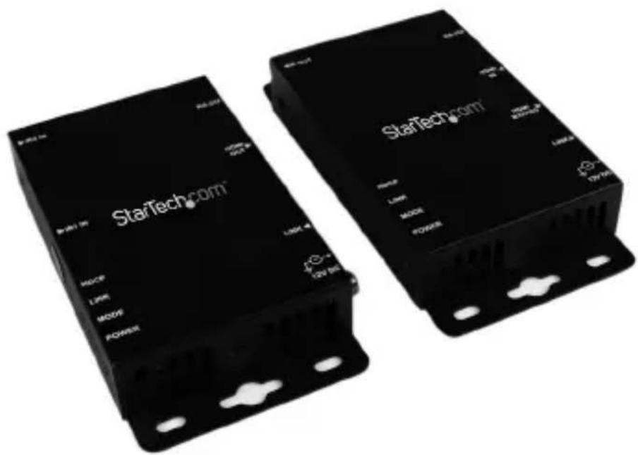
Two black StarTech.com devices with visible ports and labels, no readable text beyond branding*actual product may vary from photos
For the most up-to-date information, please visit: www.startech.com
FCC Compliance Statement
This equipment has been tested and found to comply with the limits for a Class B digital device, pursuant to part 15 of the FCC Rules. These limits are designed to provide reasonable protection against harmful interference in a residential installation. This equipment generates, uses and can radiate radio frequency energy and, if not installed and used in accordance with the instructions, may cause harmful interference to radio communications. However, there is no guarantee that interference will not occur in a particular installation. If this equipment does cause harmful interference to radio or television reception, which can be determined by turning the equipment off and on, the user is encouraged to try to correct the interference by one or more of the following measures:
• Reorient or relocate the receiving antenna.
- Increase the separation between the equipment and receiver.
- Connect the equipment into an outlet on a circuit different from that to which the receiver is connected.
- Consult the dealer or an experienced radio/TV technician for help.
Use of Trademarks, Registered Trademarks, and other Protected Names and Symbols
This manual may make reference to trademarks, registered trademarks, and other protected names and/or symbols of third-party companies not related in any way to StarTech.com. Where they occur these references are for illustrative purposes only and do not represent an endorsement of a product or service by StarTech.com, or an endorsement of the product(s) to which this manual applies by the third-party company in question. Regardless of any direct acknowledgement elsewhere in the body of this document, StarTech.com hereby acknowledges that all trademarks, registered trademarks, service marks, and other protected names and/or symbols contained in this manual and related documents are the property of their respective holders.
Table of Contents
Introduction......1
Packaging Contents .... 1
System Requirements....1
Transmitter Unit 2
Receiver Unit....3
Preparing Your Site ....4
Hardware Installation....4
Specifications......6
Technical Support 7
Warranty Information....7
Introduction
The ST121UTPHD2 HDMI ^® over CAT5 Extender Kit can extend the audio and video signal output from an HDMI ^® -equipped device by up to 330 feet (100 Meters), over a single CAT5 cable. The extender supports full High-Definition video (1080p) and HD 3D, and also extends the accompanying digital audio signal.
For convenient, time-saving control of the media source, the CAT5 HDMI extender offers bidirectional RS-232 serial and unidirectional Infrared (IR) interfaces, which enable you to control the HDMI audio-video source from either end of the connection.
The HDMI over CAT5 Extender Kit includes both the HDMI ^® to CAT5 transmitter and the CAT5 to HDMI receiver needed for a cost-effective, ready-to-use digital signage solution.
To help ensure seamless performance without any unexpected or unnecessary interruptions, the HDMI Ethernet transmitter and receiver units are fully compliant with High Speed HDMI® and HDCP standards, and each unit features lockable power connectors to prevent accidental disconnections.
The ST121UTPHD2 HDMI over CAT5 Extender Kit is backed by a StarTech.com 2-year warranty and free lifetime technical support.
Packaging Contents
• 1x Local HDMI® Extender Unit
• 1x Remote HDMI® Receiver Unit
• 1x IR Receiver Cable
• 1x IR Transmitter Cable
• 1x HDMI Cable - 4 ft (1.2 Meters)
• 2x Universal Power Adapter NA / UK / EU
- 1x User Manual
System Requirements
- HDMI® enabled video source device (i.e. computer, Blu-ray Player)
- HDMI® enabled display device (i.e. television, projector)
• Available AC electrical outlet for transmitter and receiver - HDMI® cable from receiver to display (HDMI® cable from video source to transmitter is provided)
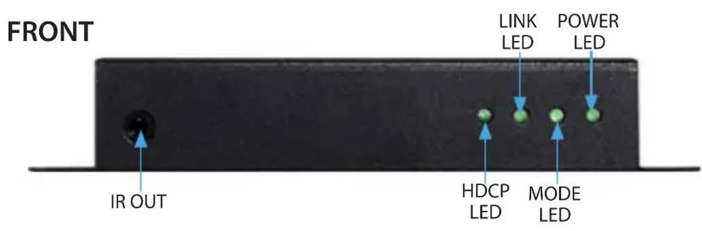
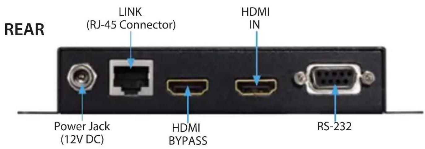
Transmitter Unit
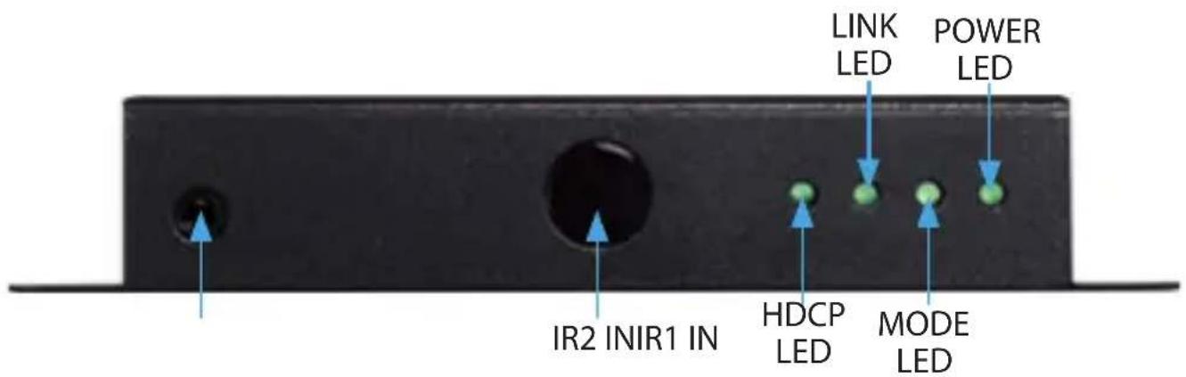
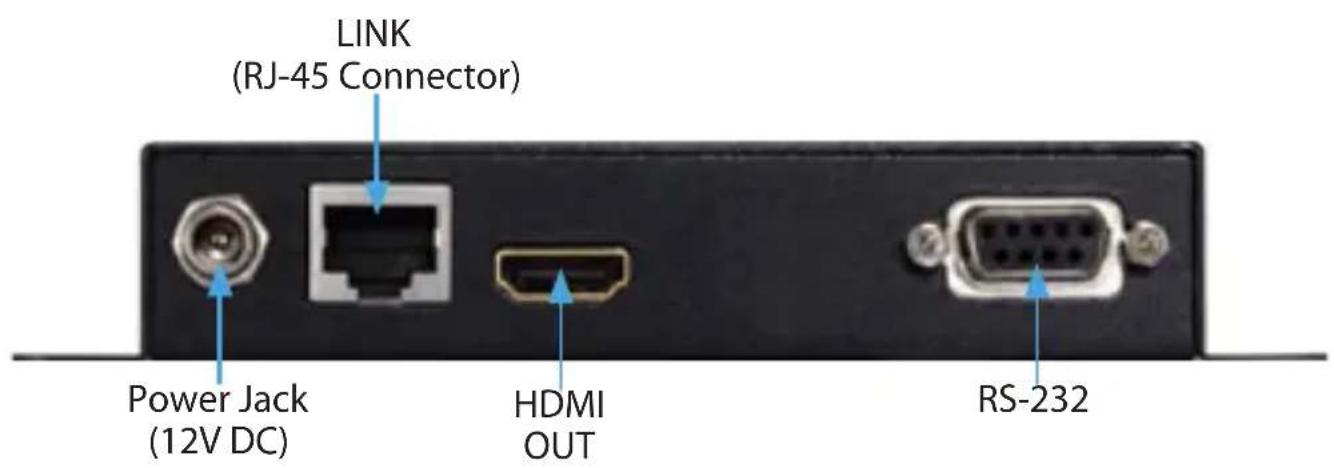
Receiver Unit
FRONT
REAR
Preparing Your Site
- Determine where the local video source (i.e. computer, Blu-ray Player) will be located and set up the device.
- Determine where the remote display will be located and place/mount the display appropriately.
Notes: Ensure the Extender Unit and the Receiver Unit are situated near an available AC electrical outlet. Make sure all devices are turned off before beginning installation.
Hardware Installation
- Install Transmitter Unit
a) Position the Transmitter Unit near the video source (i.e. Computer, Blu-ray Player).
b) Connect the provided HDMI® cable from the video source device (i.e. computer, Blu-ray Player) to the "HDMI® IN" on the Transmitter Unit.
c) Connect the provided Transmitter Unit power supply.
d) (Optional) If using the ST121UTPHD2 to extend an infrared (IR) device signal. Connect the IR Transmitter Cable to the IR OUT on the Transmitter Unit, and Position the extended IR sensor directly in front of the video source's IR sensor. Check the manual of your video source device for the IR sensor location.
e) (Optional) If you would like to use a local display, connect an HDMI® cable (Not provided) from the display to HDMI® bypass.
Note: Only the local or remote display can work at one time. Connecting a display to the HDMI® bypass will result in the remote display losing signal.
f) (Optional) If also transmitting RS-232 signals over CAT5, connect the transmitting RS-232 device to the "RS-232" connector on the Transmitter Unit using a DB9 cable (Not included).
- Install RJ45 terminated CAT5 Ethernet Cable
a) Connect an RJ45 terminated CAT5 Ethernet cable (not included) to the RJ45 connector on the Transmitter unit.
Note: If you are using surface cabling, ensure you have enough Category 5 unshielded twisted pair (UTP) network cabling to connect the Host Unit to the Remote Unit's location, and that each end is terminated with a RJ45 connector. The cabling should not go through any networking equipment (i.e. router, switch).
OR
If you are using premises cabling, ensure that the Category 5 unshielded twisted pair (UTP) network cabling between the Host Unit and the Remote Unit has been properly terminated in a wall outlet in each location and there is a patch cable long enough to connect the Remote Unit and the Host Unit to their respective outlets. The cabling should not go through any networking equipment (i.e. router, switch).
b) Connect the other end of the CAT5 cable run to the RJ45 connector on the Receiver Unit.
- Install Receiver Unit
a) Position the Receiver Unit near the video display (i.e. television, projector).
b) Connect the video source to the HDMI ^® OUT on the Receiver Unit using an HDMI ^® cable (Not included).
c) (Optional) If using the ST121UTPHD2 to extend an infrared (IR) device signal. Connect the IR Receiver Cable to the IR IN 1 on the Receiver Unit, and Position the IR sensor where the remote control will point.
Note: If you intend to point the remote control directly at the Receiver Unit, the IR Receiver cable is not required, as IR IN 2 is physically embedded into the device.
g) (Optional) If also transmitting RS-232 signals over CAT5, connect the receiving RS-232 device to the "RS-232" connector on the Receiver Unit using a DB9 cable (Not included).
d) Connect the provided Receiver Unit power supply. The Power LED will light, and LINK & HDCP LEDs will turn on after a successful connection between both units is established. This may take several seconds.
- Your source video image will now appear on the remote video display.
Specifications
| Local Unit Connectors | 1x IrDA (Infrared; SIR/FIR)2x HDMI (19 pin) Female1x DB-9 (9 pin; D-Sub) Female1x RJ-45 Female |
| Remote Unit Connectors | 2x IrDA (Infrared; SIR/FIR)1x HDMI (19 pin) Female1x DB-9 (9 pin; D-Sub) Male1x RJ-45 Female |
| Maximum Data Transfer Rate | HDMI® - 3.4GbpsRS-232 - 115200bps baud |
| Max Distance 100 m / 330 ft | |
| Maximum Digital Resolutions 4K @ 30Hz | |
| Wide Screen Supported Yes | |
| Audio Specifications Supports Dolby® TrueHD, DTS-HD MA | |
| General Specifications | IR Interface: unidirectional38Khz / ±10° / 5M |
Technical Support
StarTech.com's lifetime technical support is an integral part of our commitment to provide industry-leading solutions. If you ever need help with your product, visit www.startech.com/support and access our comprehensive selection of online tools, documentation, and downloads.
For the latest drivers/software, please visit www.startech.com/downloads
Warranty Information
This product is backed by a two year warranty.
In addition, StarTech.com warrants its products against defects in materials and workmanship for the periods noted, following the initial date of purchase. During this period, the products may be returned for repair, or replacement with equivalent products at our discretion. The warranty covers parts and labor costs only. StarTech.com does not warrant its products from defects or damages arising from misuse, abuse, alteration, or normal wear and tear.
Limitation of Liability
In no event shall the liability of StarTech.com Ltd. and StarTech.com USA LLP (or their officers, directors, employees or agents) for any damages (whether direct or indirect, special, punitive, incidental, consequential, or otherwise), loss of profits, loss of business, or any pecuniary loss, arising out of or related to the use of the product exceed the actual price paid for the product. Some states do not allow the exclusion or limitation of incidental or consequential damages. If such laws apply, the limitations or exclusions contained in this statement may not apply to you.
Hard-to-find made easy. At StarTech.com, that isn't a slogan. It's a promise.
StarTech.com is your one-stop source for every connectivity part you need. From the latest technology to legacy products — and all the parts that bridge the old and new — we can help you find the parts that connect your solutions.
We make it easy to locate the parts, and we quickly deliver them wherever they need to go. Just talk to one of our tech advisors or visit our website. You'll be connected to the products you need in no time.
Visit www.startech.com for complete information on all StarTech.com products and to access exclusive resources and time-saving tools.
StarTech.com is an ISO 9001 Registered manufacturer of connectivity and technology parts. StarTech.com was founded in 1985 and has operations in the United States, Canada, the United Kingdom and Taiwan servicing a worldwide market.
- HDMI® over CAT5 Video Extender with RS-232 and IR Control
- FCC Compliance Statement
- Use of Trademarks, Registered Trademarks, and other Protected Names and Symbols
- Table of Contents
- Introduction......1
- Transmitter Unit 2
- Receiver Unit....3
- Preparing Your Site ....4
- Hardware Installation....4
- Specifications......6
- Technical Support 7
- Warranty Information....7
- Introduction
- Packaging Contents
- System Requirements
- Transmitter Unit
- Receiver Unit
- Preparing Your Site
- Hardware Installation
- Technical Support
- Warranty Information
- Limitation of Liability
Brand : StarTech.com
Model : ST121
Category : Network switch