
ST1214TEU - Network switch StarTech.com - Free user manual and instructions
Find the device manual for free ST1214TEU StarTech.com in PDF.

| Product Type | VGA over Cat5 Transmitter (4-port) |
| Model | ST1214TEU |
| Brand | StarTech.com |
| Dimensions | 63.89 mm x 103.0 mm x 20.58 mm |
| Weight | 246 g (8.7 oz) |
| Power Adapter Input | 100-240 VAC, 50/60 Hz |
| Power Adapter Output | 12 VDC, 1.5 A |
| Connectors | 1 x DE-15 VGA male, 1 x DE-15 VGA female, 4 x RJ45 (Cat5 OUT), 1 x Power connector |
| Maximum Distance | 150 m (492 ft) at 1024x768 resolution |
| Cable Type | Standard Cat5 UTP with RJ45 connectors (EIA/TIA 568B wiring) |
| Supported Resolution | Up to 1920x1440 (depending on cable length) |
| LED Indicators | Power (green), Active (green) |
| Driver Required | No driver required (external hardware solution) |
| Operating Temperature | 0°C to 40°C (32°F to 104°F) |
| Storage Temperature | -20°C to 60°C (-4°F to 140°F) |
| Humidity (non-condensing) | 10% to 85% |
| Included Accessories | 1 x ST1214T transmitter, 1 x Universal Power Adapter, 1 x Instruction Manual |
| Mounting | Optional mounting brackets (ST121MOUNT) for surface or VESA mount |
| Warranty | 1 year |
| FCC Compliance | Class B digital device, Part 15 |
Frequently Asked Questions - ST1214TEU StarTech.com
User questions about ST1214TEU StarTech.com
0 question about this device. Answer the ones you know or ask your own.
Ask a new question about this device
Download the instructions for your Network switch in PDF format for free! Find your manual ST1214TEU - StarTech.com and take your electronic device back in hand. On this page are published all the documents necessary for the use of your device. ST1214TEU by StarTech.com.
USER MANUAL ST1214TEU StarTech.com
ST1214T / ST1214TGB / ST1214TEU ST1218T ST121R / ST121RGB / ST121REU ST121EXT / ST121EXTGB / ST121EXTEU Instruction Manual
VGA Video Extender
4/8-Port VGA over Cat5 Transmitter
VGA over Cat5 Receiver
VGA over Cat5 Extender
FCC Compliance Statement
This equipment has been tested and found to comply with the limits for a Class B digital device, pursuant to part 15 of the FCC Rules. These limits are designed to provide reasonable protection against harmful interference in a residential installation. This equipment generates, uses and can radiate radio frequency energy and, if not installed and used in accordance with the instructions, may cause harmful interference to radio communications. However, there is no guarantee that interference will not occur in a particular installation. If this equipment does cause harmful interference to radio or television reception, which can be determined by turning the equipment off and on, the user is encouraged to try to correct the interference by one or more of the following measures:
Reorient or relocate the receiving antenna.
Increase the separation between the equipment and receiver.
Connect the equipment into an outlet on a circuit different from that to which the receiver is connected.
Consult the dealer or an experienced radio/TV technician for help.
Use of Trademarks, Registered Trademarks, and other Protected Names and Symbols
This manual may make reference to trademarks, registered trademarks, and other protected names and/or symbols of third-party companies not related in any way to StarTech.com. Where they occur these references are for illustrative purposes only and do not represent an endorsement of a product or service by StarTech.com, or an endorsement of the product(s) to which this manual applies by the third-party company in question. Regardless of any direct acknowledgement elsewhere in the body of this document, StarTech.com hereby acknowledges that all trademarks, registered trademarks, service marks, and other protected names and/or symbols contained in this manual and related documents are the property of their respective holders.
Table of Contents
Introduction ...... 1
Packaging Contents....1
System Requirements ....1
ST1214T/GB/EU....2
ST121R/GB/EU 2
ST121EXT/GB/EU 3
ST1218T 3
Installation 4
Hardware Installation ....4
Driver Installation 8
Operation 8
Signal Equalizer Selector (ST121R/GB/EU, ST121EXT/GB/EU) 8
Wiring Diagram 9
Specifications 10
Technical Support 11
Warranty Information 11
Introduction
The StarTech.com Converge A/V VGA over Cat5 Video Extender system is comprised of a transmitter unit (ST1214T/ST1218T) and a receiver unit (ST121R) and optionally a repeater unit (ST121EXT). This video extender system allows you to split and extend a single VGA source signal to up to four or eight separate remote locations. The VGA signal is extended using standard Cat5 UTP cable, with a maximum distance of up to 150m (492ft) or 300m (984ft) with a repeater.
Packaging Contents
1 x ST1214T/GB/EU 4-port Transmitter Unit • or
1 x ST1218T 8-port Transmitter unit or
1 x ST121R/GB/EU Receiver Unit or
1 x ST121EXT/GB/EU Extender (Repeater) Unit
1 x Universal Power Adapter•
1 x Mounting Bracket kit (ST121R/GB/EU, ST121EXT/GB/EU only)•
1 x Instruction Manual•
System Requirements
VGA enabled video source and display•
Available power outlet at local and remote locations•
Both a Transmitter Unit and Receiver Unit(s)•
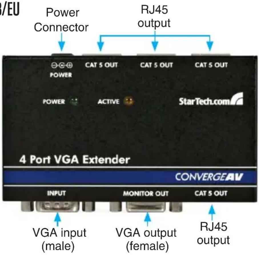
ST1214T/GB/EU
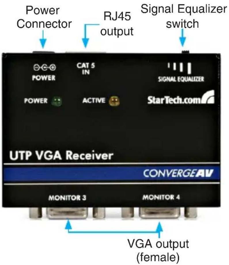
ST121R/GB/EU
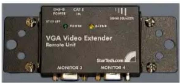
ST121EXT/GB/EU

ST1218T

Installation
NOTE: To prevent potential electrical damage to the units in some environments, ensure that the chassis is properly grounded.
Hardware Installation
The following instructions detail how ST1214T, ST1218T, ST121R and ST121EXT units can be used to extend a VGA signal to remote displays, using a variety of different configurations.
ST1214T/ST1218T (local) and ST121R (remote)
Using the Transmitter Unit, you can split the VGA signal from the 1. source into 4/8 separate VGA signals, for reception at remote locations (up to 150m (492ft) away).
Situate the Transmitter so that it is near your VGA video source as 2. well as an available power source.
Connect the Transmitter to the power source, using the power 3. adapter provided.
Connect the VGA video source to the VGA IN port on the 4. Transmitter, using a male-female VGA cable.
Situate the Receiver Unit so that it is near the intended remote 5. display(s) and an available power source.
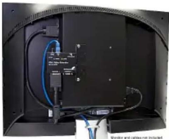
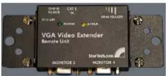
OPTIONAL: with the optional mounting brackets (StarTech.com ID: ST121MOUNT), any ST121 series receiver can be securely mounted to a surface or the back of a VESA compliant flat-panel display.
natural_image
Interior view of a computer monitor with cables and connectors (no visible text or symbols)Connect the Receiver to the power source using the power adapter 6. provided.
Using the Monitor Out ports, connect the Receiver to the display. 7. Note that each Receiver unit can be connected to two separate displays simultaneously. To connect two monitors, simply connect a VGA cable from the second Monitor Out to a second display.
Once the Transmitter and Receiver unit(s) have been positioned, 8. connect the Cat5 OUT ports provided by the Transmitter unit to each Receiver Unit, using standard UTP cable, with RJ45 connectors on each end.
The following diagram illustrates the connection between Transmitter and receiver units.
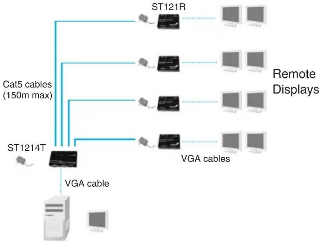
flowchart
graph TD
    A["ST1214T"] -->|VGA cable| B["Cat5 cables (150m max)"]
    A --> C["ST121R"]
    A --> D["VGA cables"]
    C --> E["Remote Displays"]
    D --> E
Video Source
ST1214T/ST1218T (local), ST121EXT (extender), ST121R (Remote)
Using the Transmitter Unit, you can split the VGA signal from the source into 4 separate VGA signals, for reception at remote locations. While the maximum transmission distance of the Transmitter is 150m (492ft), using the Extender Unit as a signal repeater adds another 150m (492ft) to the total transmission distance, for a total extension of 300m (984ft).
Situate the Transmitter Unit so that it is near your VGA video source 1. as well as an available power source.
Connect the Transmitter to the power source, using the power 2. adapter provided.
Connect the VGA video source to the VGA IN port on the 3.
Transmitter, using a standard male-female VGA cable.
Situate the Extender Unit up to 150m (492ft) away from the 4.
Transmitter unit, ensuring that the Extender Unit is able to connect to an available power outlet.
OPTIONAL: with the optional mounting brackets (StarTech.com ID: ST121MOUNT), any ST121 series receiver can be securely mounted to a surface or the back of a VESA compliant flat-panel display.
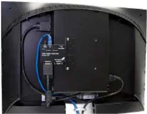
natural_image
Interior view of a computer monitor case showing cable routing and ventilation system (no visible text or symbols)Using a standard UTP cable with RJ45 terminators on each end, 5. connect the Cat5 OUT port provided by the Transmitter Unit to the Cat5 IN port provided by the Extender Unit.
Connect the Extender Unit to an available power outlet, using the 6. adapter provided.
OPTIONAL:7. You can connect two monitors directly to the Extender Unit. To do so, simply connect the monitors to the MONITOR OUT ports on the Extender Unit.
Repeat step 4 to 7 for each Receiver Unit that will be used in 8. conjunction with an Extender (up to 4).
Situate the Receiver Unit up to 150m (492ft) away from the Extender 9. Unit, so that it is near the intended display(s) as well as an available power source.
Connect the Receiver Unit to the power source using the power 10. adapter provided.
Using a standard UTP cable with RJ45 terminators on each end, 11. connect the Cat5 OUT port provided by the Extender Unit to the Cat5 IN port provided by Receiver Unit.
NOTE: Each Receiver Unit can be connected to two separate displays simultaneously. To connect two monitors, simply connect a VGA cable from the second Monitor Out port to a second display.
The following diagram illustrates the connection between Transmitter and Receiver units, with the addition of an Extender Unit. Please note that although only one Extender is used in this illustration, up to four can be used simultaneously.
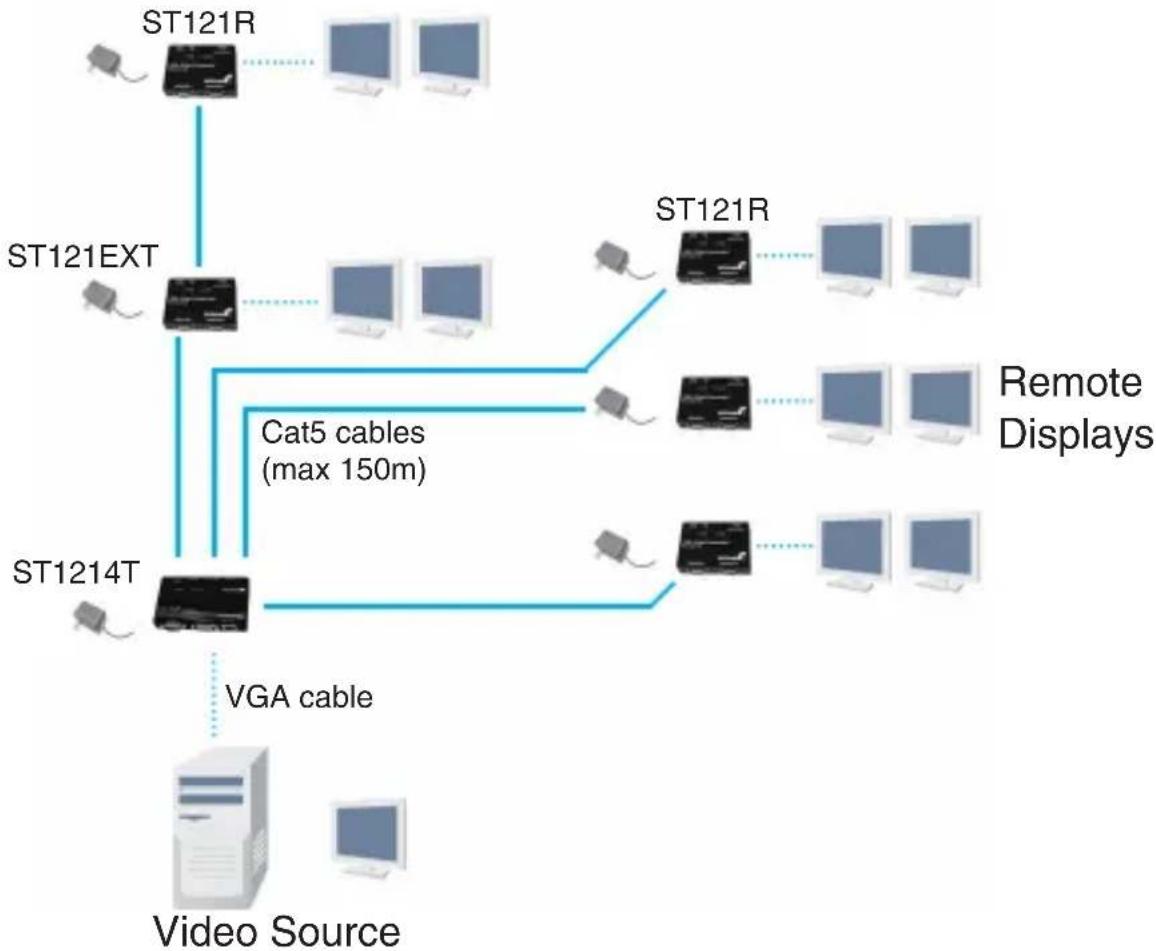
flowchart
graph TD
    A["ST121R"] --> B["ST121EXT"]
    B --> C["ST1214T"]
    C --> D["VGA cable"]
    D --> E["Video Source"]
    F["ST121R"] --> G["Remote Displays"]
    H["ST1214T"] --> I["Cat5 cables (max 150m)"]
    I --> J["Computer"]
    K["Computer"] --> L["Computer"]
    M["Computer"] --> N["Computer"]
Driver Installation
No driver installation is required for this video extender as it is an external hardware only solution, invisible to the computer system.
Operation
ST1214T/ST1218T, ST121EXT and ST121R all provide LED indicators, allowing simple operating status monitoring. Once the power adapter has been connected, the Power LED will become illuminated; similarly, when the unit is in use (i.e. transmitting a video signal), the Active LED will become illuminated.
Signal Equalizer Selector (ST121R/GB/EU, ST121EXT/GB/EU)
The Signal Equalizer Selector on the Receiver and Extender Units can be adjusted to obtain the optimal video signal for various cable lengths. There are four settings on the selector switch, indicating cables of different lengths. The following table can be used as a reference for selecting the appropriate setting:
| CAT5 cable length | Equalizer position | |
| meter | feet | |
| 0 ~ 40 | 0 ~ 131 | |
| 40 ~ 80 | 131 ~ 262 | |
| 80 ~ 120 | 262 ~ 394 | |
| 120 ~ 160 | 394 ~ 525 | |
Wiring Diagram
The Video Extenders requires an unshielded twisted pair Cat5 cable no longer than 150m (492ft). The cable must be wired according to the EIA/TIA 568B industry standard as shown below.
| Pin Wire Color Pair | ||
| 1 White/Orange 2 | ||
| 2 Orange 2 | ||
| 3 White/Green 3 | ||
| 4 Blue 1 | ||
| 5 White/Blue 1 | ||
| 6 | Green | 3 |
| 7 White/Brown 4 | ||
| 8 | Brown | 4 |

Specifications
| ST1214TST1214TGBST1214TEU | ST1218T | |
| Connectors | 1 x DE-15 VGA male1 x DE-15 VGA female4 x RJ451 x Power Connector | 1 x DE-15 VGA male1 x DE-15 VGA female8 x RJ451 x Power Connector |
| LEDs | Power, Active | |
| Maximum Distance | 150m (492 ft) @ 1024x768 | |
| Power Supply | 12VDC, 1.5A | |
| Dimensions | 63.89mm x 103.0mm x 20.58mm | 180.0mm x 85.0mm 20.0mm |
| Weight | 246g 1300g | |
| ST121RST121RGBST121REU | ST121EXTST121EXTGBST121EXTEU | |
| Connectors | 2 x DE-15 VGA female1 x RJ451 x Power Connector | 2 x DE-15 VGA female2 x RJ451 x Power Connector |
| LEDs | Power, Active | |
| Power Supply | 12VDC, 1.5A | |
| Dimensions | 84.2mm x 65.0mm x 20.5mm | 64.0mm x 103.0mm x 20.6mm |
| Weight | 171g 204g | |
Technical Support
StarTech.com's lifetime technical support is an integral part of our commitment to provide industry-leading solutions. If you ever need help with your product, visit www.startech.com/support and access our comprehensive selection of online tools, documentation, and downloads.
Warranty Information
These products are backed by a one year warranty.
In addition, StarTech.com warrants its products against defects in materials and workmanship for the periods noted, following the initial date of purchase. During this period, the products may be returned for repair, or replacement with equivalent products at our discretion. The warranty covers parts and labor costs only. StarTech.com does not warrant its products from defects or damages arising from misuse, abuse, alteration, or normal wear and tear.
Limitation of Liability
In no event shall the liability of StarTech.com Ltd. and StarTech.com USA LLP (or their officers, directors, employees or agents) for any damages (whether direct or indirect, special, punitive, incidental, consequential, or otherwise), loss of profits, loss of business, or any pecuniary loss, arising out of or related to the use of the product exceed the actual price paid for the product. Some states do not allow the exclusion or limitation of incidental or consequential damages. If such laws apply, the limitations or exclusions contained in this statement may not apply to you.
StarTech.com Making hard-to-find easy!®
StarTech.com has been making “hard-to-find easy” since 1985, providing high quality solutions to a diverse IT and A/V customer base that spans many channels, including government, education and industrial facilities to name just a few. We offer an unmatched selection of computer parts, cables, A/V products, KVM and Server Management solutions, serving a worldwide market through our locations in the United States, Canada, the United Kingdom and Taiwan.
Visit www.startech.com today for complete information about all our products and to access exclusive interactive tools such as the Cable Finder, Parts Finder and the KVM Reference Guide.


- ST1214T / ST1214TGB / ST1214TEU ST1218T ST121R / ST121RGB / ST121REU ST121EXT / ST121EXTGB / ST121EXTEU Instruction Manual
- VGA Video Extender
- FCC Compliance Statement
- Use of Trademarks, Registered Trademarks, and other Protected Names and Symbols
- Table of Contents
- Introduction ...... 1
- Installation 4
- Operation 8
- Wiring Diagram 9
- Specifications 10
- Technical Support 11
- Warranty Information 11
- Introduction
- Packaging Contents
- System Requirements
- Installation
- Hardware Installation
- ST1214T/ST1218T (local) and ST121R (remote)
- ST1214T/ST1218T (local), ST121EXT (extender), ST121R (Remote)
- Driver Installation
- Operation
- Signal Equalizer Selector (ST121R/GB/EU, ST121EXT/GB/EU)
- Wiring Diagram
- Technical Support
- Warranty Information
- Limitation of Liability
- StarTech.com Making hard-to-find easy!®
Brand : StarTech.com
Model : ST1214TEU
Category : Network switch