
SV831DUTP - Network switch StarTech.com - Free user manual and instructions
Find the device manual for free SV831DUTP StarTech.com in PDF.

| Product Type | 8-Port CAT5 UTP KVM Switch |
| Brand | StarTech.com |
| Model | SV831DUTP |
| Number of Ports | 8 (direct), up to 256 via daisy chaining |
| Port Selection Methods | Front panel pushbuttons, OSD, hotkeys |
| Maximum Resolution | 1600 x 1200 @ 60 Hz (up to 30m); 1280 x 1024 @ 60 Hz (up to 40m) |
| Connectors | Console: KB (6-pin mini-DIN), Video (HDB-15), Mouse (6-pin mini-DIN); KVM Ports: 8 x RJ-45; Daisy Chain: DB-25 F/M; F/W Upgrade: RJ-11; Power: 3-prong AC socket |
| Switches | 8 x Port Selection pushbuttons, 1 x Reset (semi-recessed), 1 x Firmware Upgrade Recovery slide, 1 x Power rocker |
| LED Indicators | On Line (8 green), Selected (8 orange), Power (1 blue), Station ID (2-digit 7-segment orange) |
| Power Input | AC 100-240V, 50/60 Hz |
| Power Consumption | 25W |
| Operating Temperature | 0-50°C |
| Storage Temperature | -20-60°C |
| Humidity | 0-80% RH |
| Housing Material | Metal |
| Weight | 2.7 kg |
| Dimensions (W x D x H) | 43.70 x 16.10 x 4.40 cm |
| Daisy Chain Capability | Up to 31 additional switches, total 256 computers |
| Hot Plug Support | Yes (for KVM ports and console ports) |
| OSD Features | Administrator/User passwords, port naming, scan/skip modes, beeper control, firmware upgrade |
| Keyboard Emulation | Mac and Sun keyboard emulation via PC keyboard |
| Included Accessories | Power adapter, mounting bracket kit, firmware upgrade cable, user manual |
| Warranty | One-year warranty |
Frequently Asked Questions - SV831DUTP StarTech.com
User questions about SV831DUTP StarTech.com
0 question about this device. Answer the ones you know or ask your own.
Ask a new question about this device
Download the instructions for your Network switch in PDF format for free! Find your manual SV831DUTP - StarTech.com and take your electronic device back in hand. On this page are published all the documents necessary for the use of your device. SV831DUTP by StarTech.com.
USER MANUAL SV831DUTP StarTech.com
StarView CAT5 UTP KVM
8 Port StarView CAT5 UTP KVM 16 Port StarView CAT5 UTP KVM
Instruction Manual
natural_image
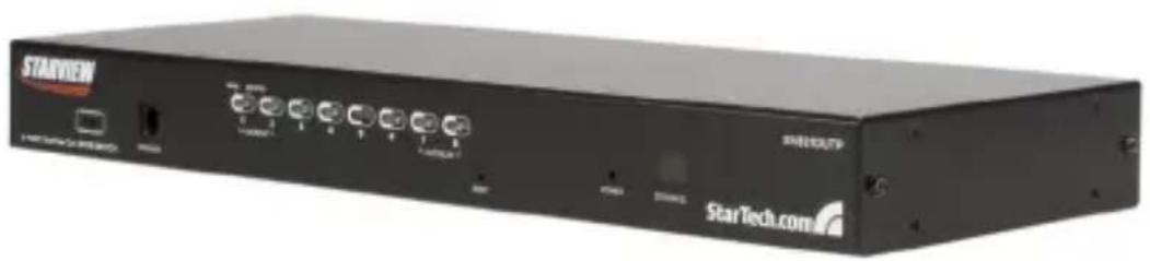
Exterior view of a black StarTech company internal unit (no visible text or symbols on body)*8 Port Model Shown
FCC Compliance Statement
This equipment has been tested and found to comply with the limits for a Class B digital device, pursuant to part 15 of the FCC Rules. These limits are designed to provide reasonable protection against harmful interference in a residential installation. This equipment generates, uses and can radiate radio frequency energy and, if not installed and used in accordance with the instructions, may cause harmful interference to radio communications. However, there is no guarantee that interference will not occur in a particular installation. If this equipment does cause harmful interference to radio or television reception, which can be determined by turning the equipment off and on, the user is encouraged to try to correct the interference by one or more of the following measures:
Reorient or relocate the receiving antenna.
Increase the separation between the equipment and receiver.
Connect the equipment into an outlet on a circuit different from that to which the receiver is connected.
Consult the dealer or an experienced radio/TV technician for help.
Use of Trademarks, Registered Trademarks, and other Protected Names and Symbols
This manual may make reference to trademarks, registered trademarks, and other protected names and/or symbols of third-party companies not related in any way to StarTech.com. Where they occur these references are for illustrative purposes only and do not represent an endorsement of a product or service by StarTech.com, or an endorsement of the product(s) to which this manual applies by the third-party company in question. Regardless of any direct acknowledgement elsewhere in the body of this document, StarTech.com hereby acknowledges that all trademarks, registered trademarks, service marks, and other protected names and/or symbols contained in this manual and related documents are the property of their respective holders.
Table of Contents
Safety Precautions .... iii
Introduction .... 1
Features ....1
Package contents ....1
Hardware Guide 2
Installation 6
Stacking Switches and Rack Mounting ....6
Single Station Installation 8
Server Interface Module Installation ....10
SV5PS2S (PS2 Module)....10
SV5USBS (USB Module) 10
Daisy Chaining ....11
Daisy Chain Installation Diagram ....12
Basic Operation 13
Port Selection ....13
Hot Plugging ....13
Powering Off and Restarting 14
Port ID Numbering ....15
OSD Operation 15
Overview 15
OSD Navigation ....17
OSD Main Screen Headings ....17
OSD Functions ....17
Hotkey Operation 27
Instruction Manual
Hotkey Port Control ......27
Auto Scanning 28
Skip Mode....29
Hotkey Beeper Control 30
Hotkey Summary Table ....30
Keyboard Emulation 32
Mac Keyboard....32
Sun Keyboard ....33
Firmware Upgrades 34
Introduction ....34
Performing the Upgrade ....35
Server Interface Module Upgrade 37
Performing the Upgrade ....38
Firmware Upgrade Recovery ....39
Connection Tables 40
Administrator Login Failure 42
OSD Factory Default Settings 43
Specifications 44
Technical Support 46
Warranty Information ....46
Safety Precautions
The following precautions should be employed to ensure safe, reliable operation of this device:
Read the enclosed instructions, and save them for future reference
Do not place the device on an unstable surface. If the device falls, • serious damage will result
Follow all warnings and instructions marked on the device (if applicable)
Do not use the device near water•
Do not place the device near or over any device that produces heat (i.e. • radiators, heat registers etc.)
To ensure adequate ventilation and reliable operation, never block the vent openings
Do not place the device on a soft surface (i.e. bed, carpet, etc.) as this will block ventilation openings. Similarly, never place the device in a built-in enclosure unless adequate ventilation is provided
Never spill liquid of any kind on the device•
Unplug the device from the wall, prior to cleaning. Do not use liquid or aerosol cleaners, instead use a damp cloth
The device should be operated from the type of power source indicated • on the marking label. If you are unsure of the type of power available, please contact your local power company
The device is equipped with a 3-wire grounding type plug. This is a safety feature that should be left intact at all times. If you are unable to insert the plug into the outlet, contact your electrician to replace the available (outdated) outlet. Do not attempt to defeat the purpose of or bypass the grounding-type plug; always follow local wiring codes
- Position system cables and power cables carefully. Do not allow anything to rest on the power cord or cables. Route the power cord and cables so that they cannot be stepped or tripped on
- If an extension cord is used with this device, make sure that the
Instruction Manual
combined ampere rating of all products used on the cord does not exceed the extension cord ampere rating. Make sure that the total of all devices connected to the wall outlet does not exceed 15 amperes
To help protect your system from sudden, transient increases and decreases in electrical power, use a surge suppressor, line conditioner or Uninterruptible Power Supply (UPS)
Follow all warnings and instructions marked on the device (if applicable)
When connecting or disconnecting power to hot pluggable power supplies, observe the following guidelines:
Install the power supply before connecting the power cable to the power supply
Unplug the power cable before removing the power supply
If the system has multiple sources of power, disconnect power by unplugging all power cables from the power supplies
Never push objects of any kind into or through cabinet slots. They may touch dangerous voltage points or short out components, risking fire or electrical shock.
Do not attempt to service the device yourself. Please refer all servicing • to qualified service personnel
Unplug the device from the wall outlet, and consult with a qualified service technician, if any of the following conditions occur:
The power cord is frayed or damaged
Liquid has been spilled into the device, or the device has been exposed to rain or water
The device has been dropped, or the casing has been damaged
The device exhibits a distinct decline in performance, indicating a
Instruction Manual
need for service
The device does not operate normally, when following the operating instructions
Only adjust controls that are described in the following operating instructions. Improper adjustment of other controls may result in damage that could lead to extensive repair
Introduction
Thank you for purchasing a StarTech.com CAT 5 KVM switch. Allowing control of up to 8 (SV831DUTP) or 16 (SV1631DUTP) computers over a CAT 5 cable connection (between the switch and the slave computers), this device provides a cost-effective solution that's simple to install, and equally easy to configure and control through pushbutton operation, hot-key commands or the convenient On-Screen Display.
Features
Auto-scan function automates sequential computer selection•
Cascade configuration expands system capability up to 256 computers • (SV831DUTP) or 512 computers (SV1631DUTP)
Allows for easy computer selection using front panel pushbuttons, hotkeys and intuitive On-Screen Display
Hot Pluggable - add or remove computers without having to power down the switch
Package contents
1 x StarView CAT5 KVM Switch
1 x User Manual
1 x Power Adapter
1 x Mounting Bracket Kit
1 x Firmware Upgrade Cable
Please note that when accessing the Switch, you will be asked to supply a Username and Password.
In the Username field, press the Enter key on the connected keyboard.
In the Password field, press the Enter key. You will then be logged into the On Screen Display.
Hardware Guide
Front Panel View SV831DUTP

Front Panel View SV1631DUTP

Please refer to the tables on pages 3 and 4 for descriptions of the above illustrations.
Instruction Manual
Component Functions (Front Panel)
| Component | Description | |
| 1 | Port Selection Switches | a. Press a switch to give the KVM focus to the computer attached to its corresponding port.b. Simultaneously pressing buttons 1 and 2 for 3 seconds performs a Keyboard and Mouse Reset.c. Simultaneously pressing buttons 7 and 8 starts Auto Scan Mode. |
| 2 | Port LEDs | The Port LEDs are built into the Port Selection Switches. The upper ones are the On Line LEDs; the lower ones are the Selected Port LEDs:a. An On Line LED lights GREEN to indicate that the computer attached to its corresponding port is up and running. A flashing LED indicates that the Port is being used for cascading to another switch.b. A Selected LED lights ORANGE to indicate that the computer attached to its corresponding port is the one that has the KVM focus.The LED is steady under normal conditions, but flashes when its port is accessed under Auto Scan Mode. |
| 3 | Reset Switch | Pressing this switch in performs a system reset. Note: The switch is recessed and must be pushed with a thin object - such as the end of a paper clip, or a ballpoint pen. |
| 4 | Firmware Upgrade Recovery Switch | During normal operation and while performing a firmware upgrade, this switch should be in the NORMAL position. If a firmware upgrade operation does not complete successfully, this switch is used to perform a firmware upgrade recovery. |
Instruction Manual
| Component | Description | |
| 5 | Firmware Upgrade Port | The Firmware Upgrade Cable that transfers the firmware upgrade data from the administrator's computer to the SV831DUTP / SV1631DUTP, plugs into this RJ-11 connector. |
| 6 | Power LED | Lights to indicate that the SV831DUTP / SV1631DUTP is powered up and ready to operate. |
| 7 | Station ID LED | The SV831DUTP / SV1631DUTP's Station ID is displayed here. If this is a Single Station installation (see page 12), or the First Station on a Daisy Chained installation (see page 15), the SV831DUTP / SV1631DUTP has a Station ID of 01.On a Daisy Chained installation, the SV831DUTP / SV1631DUTP autosenses its position and displays the Station ID that corresponds to its place in the chain. (see Port ID Numbering, page 15, for details). |
Rear Panel View (SV831DUTP)
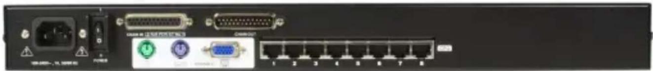
natural_image
Back panel of a network device showing ports, connectors, and Ethernet ports (no readable text or symbols)Rear Panel View (SV1631DUTP)

natural_image
Front view of a network device rear panel showing ports, connectors, and indicator lights (no readable text or symbols)Please refer to the table on page 5 for descriptions of the above illustrations.
Instruction Manual
Component Functions (Rear Panel)
| Component Description | ||
| 1 | Power Socket | |
| 2 | Power Switch | |
| 3 | Daisy Chain Ports | When Daisy Chaining Units, the daisy chain cables plug in here. The port on the left is the Chain In port; the port on the right is the Chain Out port. |
| 4 | Local Console Port Section | If this is a Single Station installation, or if this is the First Station of a daisy chained installation, the keyboard, monitor, and mouse that make up the Local Console plug in here. |
| 5 | KVM Port Section | The Cat 5 cables that link to the KVM Adapter Cables (which link to the computers) plug in here. |
Installation

Please ensure you have reviewed the safety precautions listed on page iii - v, before proceeding with installation.
Please make sure that power to all of the devices that will be connected to the switch has been shut off; similarly, you must unplug the power cords of any computers that have the Keyboard Power On function.
Stacking Switches and Rack Mounting
SV831DUTP and SV1631DUTP can be stacked on the desktop or rack mounted at the front or rear of the rack. The following sections take you through the procedures for each method.
Stacking
SV831DUTP and SV1631DUTP can be placed on any appropriate level surface that can safely support its weight plus the weight of its attached cables. To place SV831DUTP / SV1631DUTP, or to stack units if you are daisy chaining them, remove the backing material from the bottom of the rubber feet that came with this package, and stick them onto the switch's bottom panel at the corners, as shown in the diagram, below:

natural_image
Line drawing of a server rack with ports and connectors (no text or symbols)Instruction Manual
Please Note: To ensure adequate ventilation, allow at least 5.1cm (2") on each side, and 12.7cm (5") at the back for power cord and cable clearance.
Rack Mounting
SV831DUTP and SV1631DUTP can be mounted in a 19" (1U) rack. The mounting brackets can screw into either the front or the back of the unit so that it can attach to the front or the back of the rack. To rack mount the unit:
Remove the screws at the front or the rear, as shown in the diagram 1. below:

Screw the mounting brackets into the sides of the unit at the front or 2. the rear, as shown in the diagram on the following page:
Instruction Manual
M3 x 8 Philips head hex

natural_image
Technical line drawing of two server racks with mounting connectors and indicator lights (no text or symbols)M3 x 8 Philips head hex
- Slide the unit into the front or rear of the rack and secure it to the rack.
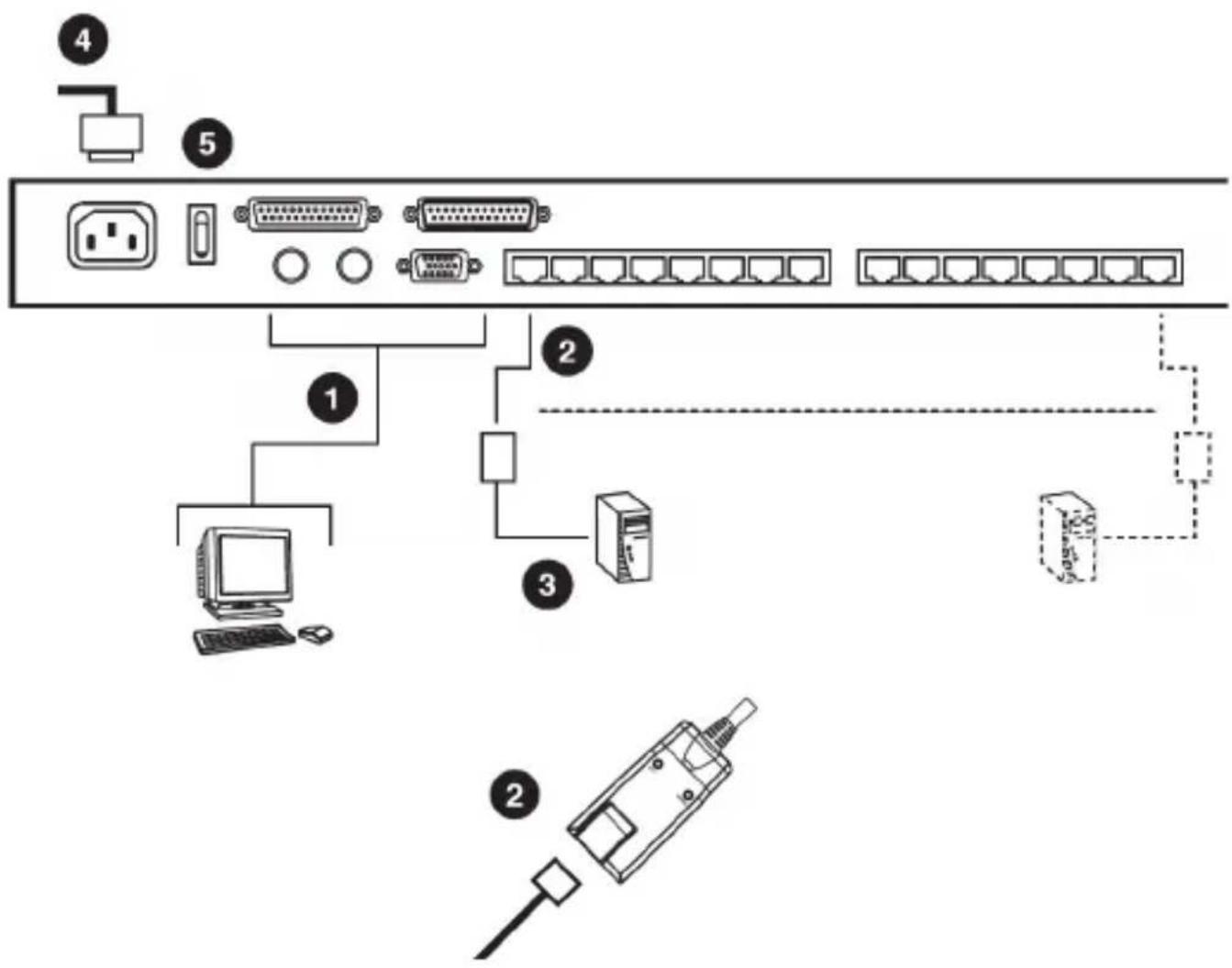
Single Station Installation
In a Single Stage installation, there are no additional KVM switches cascaded down from SV831DUTP / SV1631DUTP. To set up a single stage installation, refer to the installation diagrams on the following page (the numbers in the diagram correspond with the numbers of the instruction steps), and do the following:
Plug your Local Console's keyboard, monitor, and mouse into the unit's Console Ports. Each port is color coded and marked with an appropriate icon to identify itself.
Use Cat. 5 cable to connect any available KVM port to a KVM Adapter 2. Cable that is appropriate for the computer you are installing.
Please Note: SV831DUTP / SV1631DUTP does not support distances between itself and the KVM Adapter Cable that exceed 40 m (130').
Connect the KVM Adapter Cable to the computer. Plug the connectors 3. on the KVM Adapter Cable into the appropriate ports of the computer you are installing.
Instruction Manual
Plug the female end of the power cord into the SV831DUTP/4. SV1631DUTP Power Socket; plug the male end into an AC power source.
Turn on the power to SV831DUTP / SV1631DUTP. After the switch is 5. powered up, you can turn on the computers.
Server Interface Module Installation
SV5PS2S (PS2 Module)
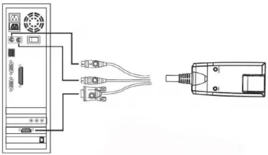
natural_image
Diagram showing connections between a server rack and an electronic device (no text or symbols present)SV5USBS (USB Module)

natural_image
Diagram showing connections between a server tower and an electronic device (no text or symbols present)Daisy Chaining
To control more computers than would be supported by SV831DUTP / SV1631DUTP in a signal stage installation (eight and sixteen respectively), up to 31 additional switches can be cascaded from the KVM ports of the SV831DUTP / SV1631DUTP. As many as 512 computers can be controlled from a single console in a complete installation.
Tables showing the relation between the number of computers and the number of SV831DUTP or SV1631DUTP units needed to control them are provided on page 40. To set up a daisy chained installation, do the following:
Use a Straight Through DB25 M/F cable (see StarTech.com part num- 1. bers SC6MF or SC10MF) to connect the Chain Out port of the parent SV831DUTP / SV1631DUTP unit to the Chain In port of the child SV831DUTP / SV1631DUTP unit (First Station Out to Second Station In, Second Station Out to Third Station In, etc.).
Please Note: You cannot use the Chain In port of the First Station, since it is the highest level parent.
Use Cat. 5 cable to connect any available KVM port to the appropriate 1. KVM Adapter Cable.
Please Note: The SV831DUTP / SV1631DUTP does not support distances between itself and the KVM Adapter Cable that exceed 40 m (130')
Connect the KVM Adapter Cable to the computer.1.
Use the power cord supplied with this package to connect the SV831DUTP / SV1631DUTP to an AC power source.
Repeat steps 1–4 for any other switches you wish to add to the chain.3.
Power up the installation according to the following procedure: 4.
a) Plug in the power adapter for the First Station. Wait for the unit to determine its Station ID and display it on the Station ID LED. (The Station ID for the First Stage unit is 01, the ID for the Second Stage unit is 02, the ID for the Third Stage unit is 03, etc.)
b) Power on each station on the installation in turn (Second Station, then Third Station, etc.). In each case, wait for the Station ID to be
Instruction Manual
displayed before powering on the next station.
c) After all stations are up, power on the computers.
Daisy Chain Installation Diagram

flowchart
graph TD
    A["Server"] --> B["Switch"]
    C["Client"] --> B
    B --> D["Rear"]
    D --> E["Switch"]
    F["Server"] --> G["Switch"]
    H["Client"] --> G
    G --> I["Rear"]
    I --> J["Switch"]
    K["Server"] --> L["Switch"]
    M["Client"] --> L
    L --> N["Rear"]
    N --> O["Switch"]
    P["Server"] --> Q["Switch"]
    R["Client"] --> Q
    Q --> S["Rear"]
    S --> T["Switch"]
    U["Server"] --> V["Switch"]
    W["Client"] --> V
    V --> X["Rear"]
    X --> Y["Switch"]
Basic Operation
Port Selection
SV831DUTP / SV1631DUTP installations provide three ways to obtain instant access to any computer in your installation: Manual, OSD, and Hotkey.
Manual
For manual port selection, simply press the Port Switch that corresponds with the device you want to access. For cascaded switches, first press the Port Switch on the parent unit that the cascaded switch is connected to, then press the Port Switch on the cascaded switch that corresponds to the device you wish to access.
OSD
OSD (On Screen Display), provides menu-driven computer switching.
Hotkey
Hotkeys allow you to conveniently direct KVM focus to a particular computer from the keyboard, instead of having to manually select the computer by pressing Port Selection switches.
Hot Plugging
SV831DUTP / SV1631DUTP supports hot plugging, allowing components to be removed and added back into the installation by unplugging and re-plugging their cables from their ports without having to shut the unit down. In order for hot plugging to work properly, however, the procedures described on the following page must be followed:
Hot Plugging Stations
You can switch station positions by simply unplugging from the old parent
Instruction Manual
and plugging into a new one. Following this, in order for the OSD menus to accordingly reflect the change, you must reset the OSD. See RESET STATION IDS, page 24, for details.
Hot Plugging KVM Ports
After switching KVM ports, in order for the OSD menus to accurately reflect the change, you must manually reconfigure the OSD information for the new Port information. See F3 SET, page 19, and the Port Setting selections under the F4 ADM function, page 21, for details.
Please Note: If the computer's Operating System doesn't support hot plugging, this function may not work properly.
Hot Plugging Console Ports
Keyboard, monitor, and mouse can all be hot plugged. When hot plugging the mouse:
You may unplug the mouse and plug it back in again (to reset the mouse, for example), as long as you use the same mouse.
If you plug in a different mouse, all the stations and all the computers • on the installation must be shut down for 10 seconds, then restarted following the Power Up Sequence described on page 9.)
Please Note: If, after hot plugging (or at any other time), there is no response to keyboard and/or mouse input, perform a Keyboard and Mouse Reset by pressing in the Reset switch (see #3, page 3).
Powering Off and Restarting
If it becomes necessary to power off the switch, or if the switch loses power and needs to be restarted, before re-starting you must follow these procedures:
Shut down all the computers that are attached to the switch. 1. Note: You must unplug the power cords of any computers that have the Keyboard Power On function.
Wait 10 seconds then power the switch back on. If you have shut down 2.
Instruction Manual
more than one station, power up the highest station first and work your way down to the lowest station. Wait for each station to display its Station ID on the front panel LED before powering on the subsequent station.
After the station(s) is (are) up, power the computers back on. 3.
Port ID Numbering
Each computer on the installation is assigned a unique Port ID. The Port ID is a one or two segment number determined by the Stage Level and KVM Port number of the KVM switch to which the computer is connected. The first segment represents the KVM Port number of the First Stage unit, the second segment represents the KVM Port number of the Second Stage unit.
A computer attached to a First Stage unit has a one segment Port ID (from 1-16) corresponding with the KVM Port number to which it is connected.
A computer attached to a Second Stage unit has a two segment Port ID:
The second segment (from 1-8), represents the KVM Port number on the Second Stage unit to which the computer is connected. The first segment (from 1-16) represents the KVM Port number on the First Stage unit to which the Second Stage unit is linked.
As an example, a Port ID of 12 - 3 refers to a computer connected to KVM Port 3 of a Second Stage unit that links back to KVM Port 12 of the First Stage unit.
OSD Operation
Overview
The On Screen Display (OSD) is a menu-driven method to handle computer control and switching operations. All procedures start from the OSD Main Screen. To pop up the Main Screen, tap [Scroll Lock] twice.
Instruction Manual
Please Note: You can optionally change the Hotkey to the Ctrl key, in which case you would tap [Ctrl] twice. With this method, the Ctrl keys used must be on the same side (both left, or both right).
The OSD incorporates a two level (Administrator / User) password system. Before the OSD Main Screen comes up, a dialog box appears that asks you to provide your password. If the password function has been set, you must provide the password in order to access the OSD Main Screen.
If this is the first time that the OSD is being run, or if the password function has not been set, simply press [Enter]. The OSD Main Screen comes up in Administrator Mode. In this mode, you have Administrator privileges, with access to all Administrator and User functions, and can set up operations (including password authorization for the future), as you would like.
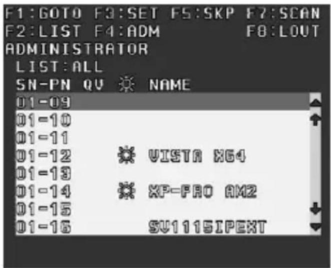
When you invoke the OSD, a screen similar to the one below appears:
Please Note:
The diagram depicts the Administrator's Main Screen. The User Main 1. Screen does not show the F4 function as it is reserved for the Administrator and cannot be accessed by ordinary Users.
The OSD always starts in List view, with the highlight bar at the same 2. position it was in the last time it was closed.
Only the ports that have been set accessible by the Administrator for 3. the currently logged in User are visible.
Instruction Manual
OSD Navigation
To dismiss the menu, and deactivate the OSD, press • [Esc]
To Logout, press • [F8]
- To move up or down through the list one line at a time, use the Up and Down Arrow Keys. If there are more list entries than there is room for on the Main Screen, the screen will scroll.
To bring the KVM focus to a port, move the Highlight Bar to it then press [Enter]
After executing any action, you automatically go back to the menu one • level above
| Heading | Explanation |
| SN-PN | This column lists the Port ID numbers (Station Number - Port Number) for all Computer Ports on the installation. The simplest method to access a particular computer is to scroll to the desired selection using the up and down arrow keys, then press Enter |
| QV | If a port has selected for Quick View scanning, an arrowhead will be displayed in this column |
 | The computers that are powered on and are On Line will be indicated in this column with a Sun symbol |
| NAME | If a port has been given a name its name appears in this column. |
OSD Main Screen Headings
OSD Functions
OSD functions are used to configure and control the OSD. For example, rapidly switching to any port, scanning only selected ports, limiting the list of ports you wish to view, designating a port as a Quick View Port, managing port names or making OSD setting adjustments.
Instruction Manual
To access an OSD function:
Press a Function Key on the keyboard.1.
In the Submenus that appear, make your choice by scrolling the 2. Highlight Bar to it, then pressing [Enter].
Press 3. [Esc] to return to the previous menu level.
F1 GOTO
Pressing [F1] activates the GOTO function. GOTO allows you to switch directly to a port either by keying in the port's Name, or its Port ID.
To use the Name method - key in 1, key in the port's Name; then press • [Enter]
To use the Port ID method - key in 2, key in the Port ID; then press • [Enter]
F2 LIST
This function allows you to broaden or narrow the scope of which ports the OSD displays (lists) on the Main Screen. Many of the OSD functions only operate on the computers currently selected for listing on the Main Screen with this function. The submenu choices and their meanings are given in the table below:
| Choice Meaning | |
| ALL | Lists all of the ports on the installation |
| POWERED ON | Lists only the ports that are connected to powered computers |
| QVIEW | Lists only the ports that have been selected as Quick View Ports |
| QVIEW + POWERED ON | Lists only the ports that have been selected as Quick View Ports and that have their attached computers powered on. |
Instruction Manual
Move the Highlight Bar to the choice you want, then press [Enter]. An icon appears before the choice indicating that it is currently selected.
F3 SET
This function allows the Administrator and each User to personalize/configure their own working environment. A separate profile for each is stored by the OSD and is activated according to the Username that is provided during Login. To change a setting:
Move the highlight bar to it, then press 1. [Enter].
After you select an item, a submenu with further choices will appear. To 2. make a selection, move the Highlight Bar to it, then press [Enter]. An icon will appear next to the selection.
| Setting Function | |
| OSD HOTKEY | Selects which Hotkey activates the OSD function:[Scroll Lock] [Scroll Lock] (default) or [Ctrl] [Ctrl]. |
| PORT ID DISPLAY POSITION | Allows you to position where the Port ID appears on the monitor. The default is the upper left corner, but you can have it appear anywhere on the screen.Use the Arrow Keys plus [Pg Up], [Pg Dn], [Home],[End], and 5 (on the numeric keypad with Num Lock off), to position the Port ID display, then press [Enter] to lock the position and return to the Set submenu. |
| PORT ID DISPLAY DURATION | Determines how long a Port ID displays on the monitor after a port change has taken place. The choices are:User Defined - Allows you to select the amount of time (from 1 - 255 sec.)Always On - which displays the Port ID at all timesIf you select User Defined, key in the number of seconds, then press [Enter]. The default is 3 Seconds. A setting of 0 (zero) disables this function. |
Instruction Manual
| Setting Function | |
| QVIEW + POWERED ON | Lists only the ports that have been selected as Quick View Ports and are connected to powered computers |
| PORT ID DISPLAY MODE | Selects how the Port ID is displayedOptions include: The Port Number alone (PORT NUMBER), the Port Name alone (PORT NAME), or the Port Number plus the Port Name (PORT NUMBER + PORT NAME) (default) |
| SCAN DURATION | Determines how long focus is given to each port as it cycles through the selected ports in Auto Scan Mode.Key in a value from 1 - 255 seconds, then press [Enter].Default is 5 seconds; a setting of 0 (zero) disables the Scan function. |
| SCAN/SKIP MODE | Selects which computers will be accessed under Skip Mode and Auto Scan ModeChoices are: ALL - All the Ports which have been set as AccessiblePOWERED ON - Only those Ports which are powered and have been set as accessible and are Powered OnQUICK VIEW - Only those Ports which have been set Accessible and have been selected as Quick View PortsQUICK VIEW + POWERED ON - Only Ports set as Accessible and have been selected as Quick View Ports and are Powered On. |
| SCREEN BLANKER | If there is no input from the console for the amount of time set with this function, the screen is blanked. Key in a value from 1 - 30 minutes, then press [Enter]A setting of 0 (zero) disables this function (default) |
| HOTKEY COMMAND MODE | Enables or Disables the Hotkey Command function in case a conflict with programs running on the computers occurs. The default is ON. |
Instruction Manual
F4 ADM
F4 is an Administrator only function, which allows the Administrator to configure the overall operation of the OSD. To change a setting use the Up and Down Arrow Keys to move the highlight bar, then press [Enter].
Following item selection, a submenu with further choices appears. Move the Highlight Bar to the desired selection, then press [Enter]. An icon appears before the selected choice for easier identification. The settings are explained in the following table:
| Setting Function | |
| SET USERNAME AND PASSWORD | This function is used to set Usernames and Passwords for the Administrator and Users:1. One Administrator and four User passwords can be set.2. After you select the Administrator field or one of the User fields, a screen that allows you to key in your password appears. The password may be up to 15 characters long, and can consist of any combination of letters and numbers (A - Z, 0 - 9).3. For each individual, key in the Username and Password, then press [Enter].4. To modify or delete a previous Username and/or Password, use the backspace key to erase individual letters or numbers. |
| SET LOGOUT TIMEOUT | If there is no input from the console for the amount of time set with this function, the Operator is automatically logged out. A login is necessary before the console can be used again.This enables other Operators to gain access to the computers when the original Operator is no longer accessing them, but has forgotten to log out. To set the timeout value, key in a number from 1 - 180 minutes, then press [Enter]. If the number is 0 (zero), this function is disabled (default). |
Instruction Manual
| Setting Function | |
| EDIT PORT NAMES | To help remember which computer is attached to a particular port, every port can be given a name. This function allows the Administrator to create, modify, or delete port names. To Edit a port name:1. Use the Navigation Keys to move the highlight bar to the port you want, then press [Enter].2. Key in the new Port Name, or modify/delete the old one. The maximum number of characters allowed for the Port Name is 12.Legal characters include:All alpha characters: a - z; A - ZAll numeric characters: 0 - 9+ - /. and SpaceThe entered information is NOT case sensitive, rather the Port Name will be displayed in all capitals.3. When you have finished editing, press [Enter] to implement the change. To abort the change, press [Esc] |
| RESTORE DEFAULT VALUES | This function is used to undo all changes and return the setup to the original factory default settings, except for the Names settings that were assigned to the Ports |
| CLEAR THE NAME LIST | Similar to Restore Default Values with the exception that this feature also clears the Names settings along with undoing all changes and returning the setup to the original factory default settings. |
| ACTIVATE BEEPER | Choices are:Y (ON) or N(OFF)When activated, the beeper sounds whenever a Port is changed, the Auto Scan function is activated or an invalid entry is made on an OSD menu |
Instruction Manual
| Setting Function | |
| SET QUICK VIEW PORTS | This function lets the Administrator select which Ports to include as Quick View ports:To select/deselect a port as a Quick View Port,• use the Navigation Keys to move the highlight bar to it, then press [Enter]When a port has been selected as a Quick View • Port, an arrowhead will be displayed in the QV column of the LIST on the Main Screen to indicate so. When a port is deselected, the arrowhead disappearsIf one of the Quick View options is chosen for • the LIST view, only a Port that has been selected here will display on the ListIf one of the Quick View options is chosen for • Auto Scanning, only a Port that has been selected here will be Auto Scanned. The default is for no ports to be selected. |
| SET ACCESSIBLE PORTS | This function allows the Administrator to define User access to the computers on the installation on a Port-by-Port basis. For each User, select the target Port, then press the [Spacebar] to cycle through the choices:F (Full access), V (View Only), or Blank (No access rights granted, Port will not appear on the User's LIST on the Main Screen.)Repeat until all access rights have been set, then press [Enter].The default is F for all users on all Ports. |
Instruction Manual
| Setting Function | |
| RESET STATION IDS | If you change the position of one of the Stations in the daisy chain, the OSD settings will no longer apply. This function directs the OSD to rescan the station positions of the entire installation and updates the OSD so that the OSD Station information corresponds to the new physical layout. Only the Station Numbers get updated. Except for the Port Names, all Administrator settings (such as Set Accessible Ports, Set Quick View Ports, etc.), for all computers affected by the change, have to be manually reset. |
| FIRMWARE UPGRADE | In order to upgrade the firmware for SV831DUTP/ SV1631DUTP you must first invoke Firmware Upgrade Mode with this setting |
| PORT SETTING | This screen lets you set three functions for the port: the length of the Cat 5 cable from the port to the KVM Adapter, the Operating System used by the computer connected to the port, and the Keyboard Language for the computer connected to the port. • Press [Spacebar] to cycle through the cable length settings: S: Short – for up to 20 m M: Medium – for between 20 and 40 m L: Long – for between 40 and 60 m An S, M, or L appears next to the port in the L column indicating the selection • Press [Enter] to cycle through the Operating System settings: PC, Mac, or Sun • Press [Tab] to cycle through the Keyboard Language settings:USA, GBR, FRA, JPN, KOR. Please Note: For German or Chinese, select USA. |
Instruction Manual
| Setting Function | |
| ADAPTERUPGRADE | In order to upgrade the Adapter Cables’ firmware, you must first invoke its Upgrade Mode with this setting |
F5 SKP
Pressing [F5] invokes Skip (SKP) Mode. This function enables you to easily skip backward or forward - switching the console focus from the currently active computer port to the previous or next available one.
The selection of computers to be available for Skip Mode switching is made with the Scan/Skip Mode setting under the F3 SET function.
When you are in Skip Mode, press [] to switch to the previous computer in the list, press [] to switch to the next computer in the list, press [] to switch to the last computer on the previous station in the list, press [] to switch to the first computer on the next station in the List.
Please Note: When you Skip, you only Skip to the previous or next available computer that is in the Scan/Skip Mode selection.
If a Port has been selected for Scan/Skip Mode, a left/right triangle symbol next to its Port ID Display will denote focus
While Skip Mode is in effect, the console will not function normally. You must exit Skip Mode in order to regain control of the console.
- To exit Skip Mode, press [Spacebar] or [Esc]
F7 SCAN
Pressing [F7] invokes Auto Scan Mode. This function allows you to automatically switch among the available computers at regular intervals so that you can monitor their activity without having to take the trouble of switching manually.
The selection of computers to be included for Auto Scanning is made • with the Scan/Skip Mode setting under the F3 SET function
The amount of time that each Port displays for is set with the Scan Duration setting under the F3 SET function. When you want to stop at a particular location, press the [Spacebar] to stop scanning and exit
Instruction Manual
Auto Scan Mode.
If the scanning stops on an empty port, or one where the computer is attached but is powered Off, the monitor screen will be blank, and the mouse and keyboard will have no effect. Simply wait - after the Scan Duration time is up, the Scan function will move on to the next port.
•
- As each computer is accessed, an S appears in front of the Port ID display to indicate that it is being accessed under Auto Scan Mode.
While Auto Scan Mode is in effect, the console will not function • normally. You must exit Auto Scan Mode in order to regain control of the console.
While you are in Auto Scan Mode, you can pause the scanning in order to keep the focus on a particular computer by pressing P
- To exit Auto Scan Mode, press [Spacebar] or [Esc]
F8 LOUT
Pressing [F8] logs you out of OSD control of the computers, and blanks the Console screen. This is different from simply pressing [Esc] when you are at the Main Screen to deactivate the OSD. With this function you must log in all over again to regain access to the OSD, whereas with [Esc], all you have to do to re-enter the OSD is tap the OSD Hotkey.
Please Note:
- When you reenter the OSD after logging out, the screen stays blank except for the OSD Main Screen. You must input your password before you can continue.
- If you re-enter the OSD after logging out, and immediately use [Esc] to deactivate the OSD without having selected a port from the OSD menu, a Null Port message displays on the screen. The OSD Hotkey will bring up the Main OSD Screen.
Hotkey Operation
Hotkey Port Control
Hotkey Port Control allows you to assign KVM focus to a particular computer directly from the keyboard. SV831DUTP/SV1631DUTP provides the following Hotkey Port Control features:
Selecting which port is active•
Auto Scanning•
Skip Mode Switching •
Invoking Hotkey Mode
All Hotkey operations begin by invoking Hotkey Mode. Invoking Hotkey Mode takes three steps:
Hold down the 1. [Num Lock] key
Press and release the 2. [-] (minus) key
Release the 3. [Num Lock] key:
[Num Lock] + [-] (Please Note: The minus key must be released within one half second, otherwise Hotkey invocation is cancelled and has no effect.
When Hotkey Mode is active:
The Caps Lock, and Scroll Lock LEDs flash in succession to indicate Hotkey Mode. They stop flashing and revert to normal status when you exit Hotkey Mode.
A Command Line appears on the monitor screen. The command line prompt is the word “Hotkey” (no quote marks) in yellow text on a blue background, and displays the subsequent Hotkey information that you key in
Ordinary keyboard and mouse functions are suspended - only Hotkey • compliant keystrokes (described in the sections that follow), can be
input. Pressing [Esc] exits Hotkey Mode.
Selecting the Active Port
Each Computer Port is assigned a Port ID. You can directly access any computer on the installation with a Hotkey combination that specifies the Port ID of the Computer Port that the computer is connected to. The steps involved are:
Invoke Hotkey Mode.1.
Key in the Port ID. The Port ID numbers display on the Command Line 2. as you key them in. If you make a mistake, use [Backspace] to erase the wrong number.
Press 3. [Enter]. The KVM focus switches to the designated computer and you automatically exit Hotkey Mode.
Auto Scanning
Auto Scan automatically switches among all the active Computer Ports that are accessible to the currently logged on User at regular intervals, so that activity can be automatically monitored.
Setting the Scan Interval
The amount of time Auto Scan dwells on each port is set with the SCAN DURATION setting of the OSD F3 SET function. You can change the scan interval before activating Hotkey Auto Scanning, if you wish, with the following Hotkey combination:
Invoke Hotkey Mode.1.
-
Key in [T] [n] Where [T] is the letter T, and [n] is a number from 1-255 that represents the number of seconds for the dwell time. (The letter T and the numbers display on the Command Line as you key them in. If you make a mistake, use [Backspace] to erase the wrong number.)
-
Press [Enter]. After you press [Enter], you automatically exit Hotkey Mode, and are ready to invoke Auto Scanning.
Instruction Manual
Invoking Auto Scan
To start Auto Scanning, key in the following Hotkey combination:
Invoke Hotkey Mode.1.
Press 2. [A]. After you press A, you automatically exit Hotkey Mode, and enter Auto Scan Mode, and Auto Scanning begins.
While you are in Auto Scan Mode, you can pause the scanning in order to maintain focus on a particular computer by pressing [P]. While Auto Scanning is paused, the Command Line displays: Auto Scan: Paused.
Pausing when you want to keep the focus on a particular computer is more convenient than Exiting Auto Scan Mode because when you resume scanning, you start from where you left off. If, on the other hand, you exited and restarted, scanning would start over from the very first computer on the installation.
To resume Auto Scanning from where it left off, press any key. •
While Auto Scan Mode is in effect, ordinary keyboard and mouse functions are suspended - only Auto Scan Mode compliant keystrokes can be input. You must exit Auto Scan Mode in order to regain normal control of the console.
- To exit Auto Scan Mode press [Esc] or [Spacebar].
Skip Mode
This feature allows you to switch between computers in order to monitor them manually. You can dwell on a particular port for as long or as little as you like, as opposed to Auto Scanning which automatically switches after a fixed interval. To invoke Skip Mode, key in the following Hotkey combination:
Invoke Hotkey Mode.1.
- Key in [Arrow] (Where [Arrow] refers to one of the Arrow keys). After pressing the [Arrow], you automatically exit Hotkey Mode, and enter Skip Mode where you can switch ports as follows:
← Skips from the current port to the first accessible port that precedes it
Instruction Manual
→ Skips from the current port to the next accessible port
↑ Skips from the current port to the last accessible port of the previous station
↓ Skips from the current port to the first accessible port of the next station
Once you are in Skip Mode, you can keep on skipping by pressing the Arrow keys. You don't have to use the [NumLock] + [-] combination again.
While Skip Mode is in effect, ordinary keyboard and mouse functions are suspended, allowing only Skip Mode compliant keystrokes can be input. You must exit Skip Mode in order to regain normal control of the console.
To exit Skip Mode, press [Esc] or [Spacebar]. 3.
Hotkey Beeper Control
The Beeper can be Hotkey toggled On and Off. To toggle the Beeper, key in the following Hotkey combination:
- Invoke Hotkey Mode.
- Press [B]. After you press B, the Beeper toggles On or Off. The Command Line displays Beeper On or Beeper Off for one second, then the message disappears and you automatically exit Hotkey Mode.
Hotkey Summary Table
The table on the following page summarizes Hotkey operations on SV831DUTP/ SV1631DUTP:
Instruction Manual
| [Num Lock] + [-] | [Port ID][Enter] | Switches access to the computer that corresponds to that Port ID |
| [T] [n] [Enter] | Sets the Auto Scan interval to n seconds - where n is a number from 1 - 255 | |
| [A] | Invokes Auto Scan Mode. When Auto Scan Mode is in effect, [P] pauses Auto Scanning. When Auto Scanning is paused, pressing any key resumes Auto Scanning. | |
| [←] | Invokes Skip Mode and skips from the current port to the first accessible port previous to it | |
| [→] | Invokes Skip Mode and skips from the current port to the next accessible port. | |
| [↑] | Invokes Skip Mode and skips from the current port to the last accessible port of the previous Station. | |
| [↓] | Invokes Skip Mode and skips from the current port to the first accessible port of the next Station. | |
| [B] | Toggles the Beeper On or Off. |
Keyboard Emulation
Mac Keyboard
The PC compatible (101/104 key) keyboard can emulate the functions of the Mac keyboard. The emulation mappings are listed in the table below:
| PC Keyboard Mad | Keyboard |
| [Shift] Shift | |
| [Ctrl] Ctrl | |
 | |
| [Ctrl] [1] |  |
| [Ctrl] [2] |  |
| [Ctrl] [3] |  |
| [Ctrl] [4] |  |
| [Alt] Alt | |
| [Print Screen] F13 | |
| [Scroll Lock] F14 | |
| = | |
| [Enter] Return | |
| [Backspace] Delete | |
| [Insert] Help | |
| [Ctrl] | F15 |
Please Note: When using key combinations, press and release the first key (Ctrl), then press and release the activation key.
Instruction Manual
Sun Keyboard
The PC compatible (101/104 key) keyboard can emulate the functions of the Sun keyboard when the Control key [Ctrl] is used in conjunction with other keys. The corresponding functions are shown in the table below:
| PC Keyboard Sun Keyboard | |
| [Ctrl] [T] | Stop |
| [Ctrl] [F2] | Again |
| [Ctrl] [F3] | Props |
| [Ctrl] [F4] | Undo |
| [Ctrl] [F5] | Front |
| [Ctrl] [F6] | Copy |
| [Ctrl] [F7] | Open |
| [Ctrl] [F8] | Paste |
| [Ctrl] [F9] | Find |
| [Ctrl] [F10] | Cut |
| [Ctrl] [1] |  |
| [Ctrl] [2] |  |
| [Ctrl] [3] |  |
| [Ctrl] [4] |  |
| [Ctrl] [H] | Help |
 | Compose |
| [W3K] | ◆ |
Please Note: When using key combinations, press and release the first key (Ctrl), then press and release the activation key.
Firmware Upgrades
Introduction
As new firmware revisions become available for SV831DUTP/SV1631DUTP, upgrade packages will be posted on our web site:
http://www.startech.com/Downloads
Before You Begin
To prepare for the firmware upgrade, please do the following:
- From a computer that is not part of your KVM installation, visit the Downloads section of our website and enter the appropriate model name (SV831DUTP or SV1631DUTP) in the Product ID field to view any available updates.
- Choose the Firmware Upgrade Package you want to install (usually the most recent), and download it to your computer.
- Using a straight through DB25 M/F serial cable (please see Accessory Products from StarTech.com) connect a COM port on the computer to which the update has been downloaded to the Firmware Upgrade Port of SV831DUTP/SV1631DUTP.

Instruction Manual
Please Note: On a daisy chained installation, connect the cable to the First Station (Master) unit. The chained stations (Slaves) will receive the upgrade via the daisy chain cables.
Shut down all of the computers - but not the Stations - on your KVM 1. installation.
From your KVM switch console, bring up the OSD and select the 2. F4ADM function.
Scroll down to FIRMWARE UPGRADE. Press 3. [Enter], then press [Y] to invoke Firmware Upgrade Mode. For your reference, the current firmware upgrade version displays on the screen.
Performing the Upgrade
Starting the Upgrade
To upgrade your firmware:
Run the downloaded Firmware Upgrade Package file - either by double 1. clicking the file icon, or by opening a command line and keying in its location.
When the Firmware Upgrade Utility Welcome screen appears, please 2. review the License Agreement, enable the I Agree radio button, and click on Next.
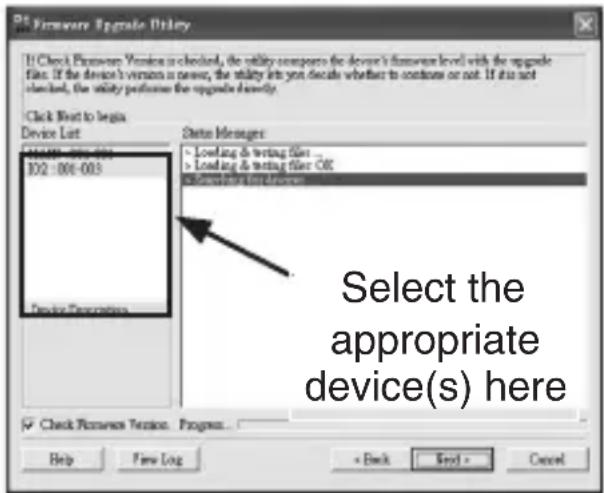
The Firmware Upgrade Utility main 3. screen will appear and inspect your installation. All of the devices capable of being upgraded by the downloaded package will be listed in the Device List panel. Highlight the devices you wish to upgrade and click on Next.
If you enabled Check Firmware 4. Version, the Utility compares the device's firmware level with that of the upgrade files. If it finds that the version already installed is higher than the upgrade version, it brings up a dialog box informing you of the situation and gives you the option to Continue or Cancel.
Instruction Manual
If you didn't enable Check Firmware Version, the Utility installs the upgrade files without checking whether they are a higher level or not.
As the Upgrade proceeds, status messages appear in the Status 5. Messages panel and the progress toward completion is shown on the Progress bar.
To abort the upgrade procedure before it completes, click 6. Cancel. If you cancel before completion, a dialog box appears warning you that quitting at this point may cause the device firmware to be lost, and you are given the option to proceed or abort the cancel operation.
Upgrade Succeeded
After the upgrade has completed, a screen appears to inform you that the procedure was successful. Click Finish to close the Firmware Upgrade Utility.
Upgrade Failed
If the upgrade failed to complete successfully a dialog box appears asking if you want to retry. Click Yes to retry. If you Click No, the Upgrade Failed screen appears. Click Cancel to close the Firmware Upgrade Utility. See the next section, entitled Firmware Upgrade Recovery, for directions on how to proceed.
Firmware Upgrade Recovery
The following situations require firmware upgrade recovery:
When the unit's firmware becomes corrupted for some reason, • rendering inoperable
When you invoke Firmware Upgrade Mode, but decide not to proceed • with the upgrade
When a firmware upgrade procedure is interrupted or fails•
Instruction Manual
To perform a firmware upgrade recovery, do the following:
Slide the Firmware Upgrade Recovery Switch to the Recover position1.
Power off and restart the switch according to the instructions given in 2. the section entitled Powering Off and Restarting.
Slide the Firmware Upgrade Recovery Switch back to the Normal 3. position.
Repeat Step 2.4.
Please Note: If one of the child units fails to upgrade successfully, unchain it from the installation and perform the recovery and upgrade operation on it independently. After it has been successfully upgraded, plug it back into the chain.
Server Interface Module Upgrade
The firmware for the SV5USBS and SV5PS2S Server Interface Modules can also be upgraded. To find the latest upgrade packages and information relating to them, please visit:
http://www.startech.com/Downloads
Before You Begin to prepare for the firmware upgrade, do the following:
From a computer that is not part of your KVM installation go to our 1. Internet support site and choose the model name that relates to your device to get a list of available Firmware Upgrade Packages.
Choose the Firmware Upgrade Package you want to install (usually the 2. most recent), and download it to your computer.
Please Note: The upgrade files for the Server Interface Modules aren't packaged separately. A single upgrade package provides the upgrade files for both units.
-
Shut down all of the computers - but not the Stations - on your KVM installation.
-
From your KVM switch console, bring up the OSD (see page 21) and
Instruction Manual
select the F4ADM function.
- Scroll down to ADAPTER UPGRADE. Press [Enter].
- In the screen that comes up, press [Y] to invoke Upgrade Mode.
Please Note:
A message appears reminding you to connect an adapter cable. The 1. message appears even if you have adapter cables connected. If all the adapter cables you want to upgrade have already been connected, simply ignore the message.
The upgrade takes place via the Cat 5 cable that connects the adapter 2. cable to the KVM switch - so there is no firmware upgrade cable to attach.
All the connected adapter cables get upgraded during a single upgrade 3. session.
Performing the Upgrade
Starting the Upgrade
To upgrade your firmware:
- Run the downloaded Firmware Upgrade Package file - either by double-clicking the file icon, or by opening a command line and keying in its location.
- When the Firmware Upgrade Utility Welcome screen appears, please review the License Agreement, enable the I Agree radio button, and click on Next.
- The Firmware Upgrade Utility main screen will appear and inspect your installation. All of the devices capable of being upgraded by the downloaded package will be listed in the Device List panel. Highlight the devices you wish to upgrade and click on Next.
- If you enabled Check Firmware Version, the Utility compares the device's firmware level with that of the upgrade files. If it finds that the version already installed is higher than the upgrade version, it brings up a dialog box informing you of the situation and gives you the option to Continue or Cancel.
If you didn't enable Check Firmware Version, the Utility installs the
Instruction Manual
upgrade files without checking whether they are a higher level or not.
As the Upgrade proceeds, status messages appear in the Status Messages panel, and the progress toward completion is shown on the Progress bar.
After the upgrade has completed, a screen will appear informing you that the procedure was successful. Please click on Finish to conclude the firmware upgrade.
Please note: The KVM switch will automatically restart, following the upgrade.
Firmware Upgrade Recovery
The following situations require firmware upgrade recovery:
When the unit's firmware becomes corrupted for some reason, • rendering inoperable
When you invoke Firmware Upgrade Mode, but decide not to proceed with the upgrade
When a firmware upgrade procedure is interrupted or fails•
To perform a firmware upgrade recovery, do the following:
Unplug the Adapter Cable from the computer to which it is connected.1.
Slide its Firmware Upgrade Recovery Switch (located next to the Cat 5 2. connector) to the Recover position.
Plug the adapter cable back into the computer.3.
From your KVM switch console, bring up the OSD) and select the 4. F4ADM function.
Scroll down to ADAPTER UPGRADE. Press 5. [Enter].
Press 6. [Y] to invoke Upgrade Mode.
-
Proceed with the firmware upgrade as described in the preceding section.
-
After the upgrade completes and the switch restarts, unplug the Adapter Cable from the computer and slide the Firmware Upgrade
Instruction Manual
Recovery Switch back to the Normal position.
Plug the adapter cable back into the computer. This completes the 9. recovery procedure.
Connection Tables
The following table indicates the relationship between the number of SV831DUTP/SV1631DUTP units and the number of computers that they control:
SV831DUTP
| # of Units | Slaves | # of Units | Slaves | # of Units | Slaves | # of Units | Slaves |
| 1 | 1 - 8 | 9 | 65 - 72 | 17 | 129 - 136 | 25 | 193 - 200 |
| 2 | 9 - 16 | 10 | 73 - 80 | 18 | 137 - 144 | 26 | 201 - 208 |
| 3 | 17 - 24 | 11 | 81 - 88 | 19 | 145 - 152 | 27 | 209 - 216 |
| 4 | 25 - 32 | 12 | 89 - 96 | 20 | 153 - 160 | 28 | 217 - 224 |
| 5 | 33 - 40 | 13 | 97 - 104 | 21 | 161 - 168 | 29 | 225 - 232 |
| 6 | 41 - 48 | 14 | 105 - 112 | 22 | 169 - 176 | 30 | 233 - 240 |
| 7 | 49 - 56 | 15 | 113 - 120 | 23 | 177 - 184 | 31 | 241 - 248 |
| 8 | 57 - 64 | 16 | 121 - 128 | 24 | 185 - 192 | 32 | 249 - 256 |
Instruction Manual
SV1631DUTP
| # of Units | Slaves | # of Units | Slaves | # of Units | Slaves | # of Units | Slaves |
| 1 | 1 - 16 | 9 | 129 - 144 | 17 | 257 - 272 | 25 | 385 - 400 |
| 2 | 17 - 32 | 10 | 145 - 160 | 18 | 273 - 288 | 26 | 401 - 416 |
| 3 | 33 - 48 | 11 | 161 - 176 | 19 | 289 - 304 | 27 | 417 - 432 |
| 4 | 49 - 64 | 12 | 177 - 192 | 20 | 305 - 320 | 28 | 433 - 448 |
| 5 | 65 - 80 | 13 | 193 - 208 | 21 | 321 - 336 | 29 | 449 - 464 |
| 6 | 81 - 96 | 14 | 209 - 224 | 22 | 337 - 352 | 30 | 465 - 480 |
| 7 | 97- 112 | 15 | 225 - 240 | 23 | 353 - 368 | 31 | 481 - 496 |
| 8 | 113 - 128 | 16 | 241 - 256 | 24 | 369 - 384 | 32 | 497 - 512 |
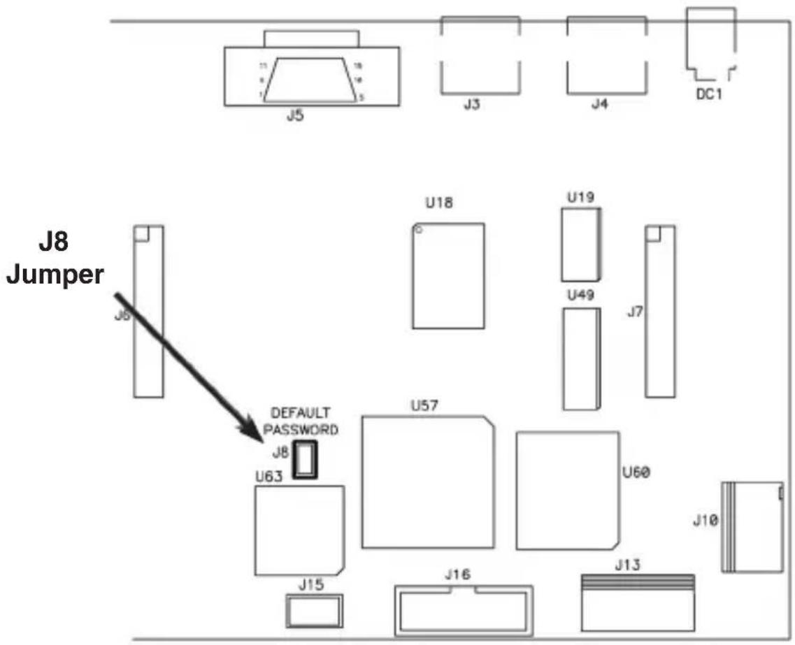
Administrator Login Failure
If you are unable to perform an Administrator login (because the Username and Password information has become corrupted or you have forgotten it, for example) you can clear the login information with the following procedure:
- Power off the SV831DUTP / SV1631DUTP and remove its housing.
- Short the jumper labeled J8.
OSD Factory Default Settings
| Setting Default | |
| OSD Hotkey | [Scroll Lock] [Scroll Lock] |
| Port ID Display Position | Upper Left Corner |
| Port ID Display Duration | 3 Seconds |
| Port ID Display Mode | The Port Number plus the Port Name |
| Scan Duration | 5 Seconds |
| Scan/Skip Mode | All |
| Screen Blanker | 0 (Disabled) |
| Hotkey Command Mode | On |
| Set Logout Timeout | 0 (Disabled) |
| Restore Default Values | N |
| Clear the Name List | N |
| Activate Beeper | ON |
| Set Accessible Ports | F (Full) For all Users on all Ports |
| Firmware Upgrade | N |
Specifications
| Function SV831DUTP | SV1631DUTP | |||
| Slave Connections | Direct 8 16 | |||
| Maximum (Daisy Chained) | 256 512 | |||
| Port Selection | OSD (On Screen Display); Hotkeys Pushbutton Switches | |||
| Connectors | Console | KB 1 x 6 | -pin Mini-DIN F (Purple) | |
| Video 1 x HDB-15 F | ||||
| Mouse 1 x 6-pin Mini-DIN F (Green) | ||||
| KVM Ports 8 x R | RJ-45 16 x RJ-45 | |||
| Daisy Chain 1 x DB-25 F; 1 x DB-25 M | ||||
| F/W Upgrade 1 x RJ-11 | ||||
| Power 3-Prong AC socket | ||||
| Switches | Port Selection 8 x | Pushbutton 16 x Pushbutton | ||
| Reset | 1 x Semi-recessed pushbutton | |||
| F/W Upgrade | 1 x Slide | |||
| Power | 1 x Rocker | |||
| LEDs | On Line | 8 (Green) 16 (Green) | ||
| Selected | 8 (Orange) | 16 (Orange) | ||
| Power 1 (Blue) | ||||
| Station ID | 2 x 7-segment (Orange) | |||
| I/P Rating | AC 100–240V; 50/60 Hz | |||
| Power Consumption | 25 W | 27W | ||
Instruction Manual
Specifications - Cont'd
| Function SV831DUTP | SV1631DUTP | ||
| Emulation | Keyboard / Mouse PS/2 | ||
| Scan Interval | 1–255 secs. | ||
| Video | 1600 x 1200 @ 60Hz (30m);1280 x 1024 @ 60Hz (40m);DDC2B | ||
| Environment | Operating Temp. 0–50o C | ||
| Storage Temp. -20–60o C | |||
| Humidity 0–80% RH | |||
| Physical Properties | Housing Metal | ||
| Weight 2.7 kg | |||
| Dimensions 43.70 x 16.10 x 4.40 cm | |||
Instruction Manual
Technical Support
StarTech.com's lifetime technical support is an integral part of our commitment to provide industry-leading solutions. If you ever need help with your product, visit www.startech.com/support and access our comprehensive selection of online tools, documentation, and downloads.
Warranty Information
This product is backed by a one-year warranty. In addition, StarTech.com warrants its products against defects in materials and workmanship for the periods noted, following the initial date of purchase. During this period, the products may be returned for repair, or replacement with equivalent products at our discretion. The warranty covers parts and labor costs only. StarTech.com does not warrant its products from defects or damages arising from misuse, abuse, alteration, or normal wear and tear.
Limitation of Liability
In no event shall the liability of StarTech.com Ltd. and StarTech.com USA LLP (or their officers, directors, employees or agents) for any damages (whether direct or indirect, special, punitive, incidental, consequential, or otherwise), loss of profits, loss of business, or any pecuniary loss, arising out of or related to the use of the product exceed the actual price paid for the product. Some states do not allow the exclusion or limitation of incidental or consequential damages. If such laws apply, the limitations or exclusions contained in this statement may not apply to you.
StarTech.com Making hard-to-find easy!
StarTech.com has been making “hard-to-find easy” since 1985, providing high quality solutions to a diverse IT and A/V customer base that spans many channels, including government, education and industrial facilities to name just a few. We offer an unmatched selection of computer parts, cables, A/V products, KVM and Server Management solutions, serving a worldwide market through our locations in the United States, Canada, the United Kingdom and Taiwan.
Visit www.startech.com today for complete information about all our products and to access exclusive interactive tools such as the Cable Finder, Parts Finder and the KVM Reference Guide. StarTech.com makes it easy to complete almost any IT or A/V solution. Find out for yourself why our products lead the industry in performance, support, and value.


- StarView CAT5 UTP KVM
- Port StarView CAT5 UTP KVM 16 Port StarView CAT5 UTP KVM
- Instruction Manual
- FCC Compliance Statement
- Use of Trademarks, Registered Trademarks, and other Protected Names and Symbols
- Table of Contents
- Safety Precautions .... iii
- Introduction .... 1
- Hardware Guide 2
- Installation 6
- Basic Operation 13
- OSD Operation 15
- Hotkey Operation 27
- Hotkey Beeper Control 30
- Keyboard Emulation 32
- Firmware Upgrades 34
- Server Interface Module Upgrade 37
- Connection Tables 40
- Administrator Login Failure 42
- OSD Factory Default Settings 43
- Specifications 44
- Safety Precautions
- Introduction
- Features
- Package contents
- Hardware Guide
- Rear Panel View (SV831DUTP)
- Rear Panel View (SV1631DUTP)
- Installation
- Stacking Switches and Rack Mounting
- Stacking
- Rack Mounting
- Single Station Installation
- Server Interface Module Installation
- SV5PS2S (PS2 Module)
- SV5USBS (USB Module)
- Daisy Chaining
- Basic Operation
- Port Selection
- Manual
- OSD
- Hotkey
- Hot Plugging
- Hot Plugging Stations
- Hot Plugging KVM Ports
- Hot Plugging Console Ports
- Powering Off and Restarting
- Port ID Numbering
- OSD Operation
- Overview
- Please Note:
- OSD Navigation
- OSD Main Screen Headings
- OSD Functions
- F1 GOTO
- F2 LIST
- F3 SET
- F4 ADM
- F5 SKP
- F7 SCAN
- Auto Scan Mode.
- F8 LOUT
- Hotkey Operation
- Hotkey Port Control
- Invoking Hotkey Mode
- Selecting the Active Port
- Auto Scanning
- Setting the Scan Interval
- Invoking Auto Scan
- Skip Mode
- Hotkey Beeper Control
- Hotkey Summary Table
- Keyboard Emulation
- Mac Keyboard
- Sun Keyboard
- Firmware Upgrades
- Before You Begin
- Performing the Upgrade
- Starting the Upgrade
- Upgrade Succeeded
- Upgrade Failed
- Firmware Upgrade Recovery
- Server Interface Module Upgrade
- http://www.startech.com/Downloads
- To perform a firmware upgrade recovery, do the following:
- Connection Tables
- Administrator Login Failure
- OSD Factory Default Settings
- Technical Support
- Warranty Information
- Limitation of Liability
- StarTech.com Making hard-to-find easy!
Brand : StarTech.com
Model : SV831DUTP
Category : Network switch