
TF 545P - Milling machine HUSQVARNA - Free user manual and instructions
Find the device manual for free TF 545P HUSQVARNA in PDF.


| Product Type | Milling Machine |
| Brand | Husqvarna |
| Model | TF 545P |
| Engine Type | Diesel |
| Engine Power | 45 kW (60 hp) |
| Cutting Width | 500 mm |
| Cutting Depth | 0-150 mm |
| Overall Dimensions (L x W x H) | 2500 x 1200 x 1500 mm |
| Operating Weight | 800 kg |
| Fuel Tank Capacity | 50 L |
| Hydraulic System | Yes, for depth adjustment |
| Travel Speed | 0-4 km/h |
| Rotor Type | Planetary with carbide tools |
| Water Spray System | Integrated for dust suppression |
| Safety Features | Emergency stop, operator presence control, rollover protection (ROPS) |
| Maintenance Interval | Every 10 hours of operation |
| Repairability | Modular design, spare parts available via dealer |
| Warranty | 2 years or 2000 hours |
Frequently Asked Questions - TF 545P HUSQVARNA
User questions about TF 545P HUSQVARNA
0 question about this device. Answer the ones you know or ask your own.
Ask a new question about this device
Download the instructions for your Milling machine in PDF format for free! Find your manual TF 545P - HUSQVARNA and take your electronic device back in hand. On this page are published all the documents necessary for the use of your device. TF 545P by HUSQVARNA.
USER MANUAL TF 545P HUSQVARNA
natural_image
Close-up of an orange car hood with a stylized '3' logo on the surface (no text or symbols visible)natural_image
Simple line drawing of an open book enclosed in a circle (no text or symbols)Please read the operator's manual carefully and make sure you understand the instructions before using the machine.





natural_image
Technical line drawing of a mechanical assembly with no visible text or symbols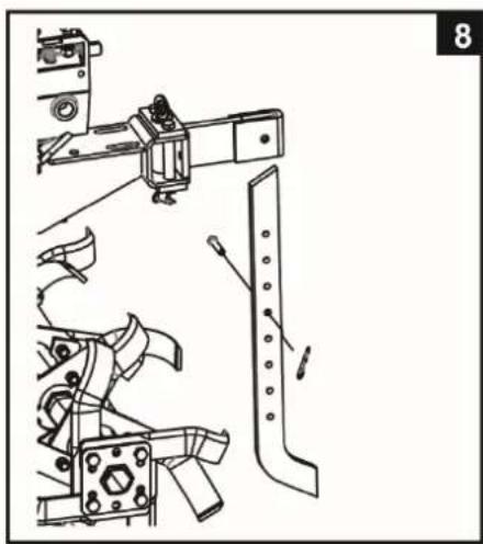
natural_image
Technical line drawing of mechanical assembly with no visible text or symbols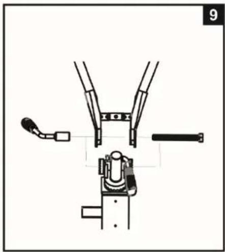
natural_image
Technical line drawing of a mechanical clamp or bracket assembly (no text or symbols)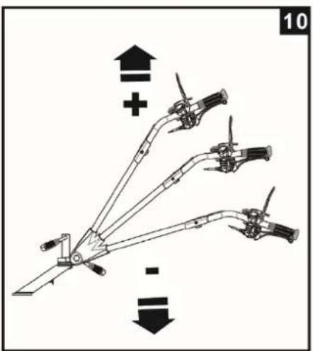
natural_image
Diagram of a mechanical linkage system with multiple arms and joints, showing directional arrows (no text or labels)
natural_image
Technical line drawing of a mechanical tripod structure with multiple arms and legs, no text or symbols present
natural_image
Diagram of a mechanical lever mechanism with motion arrows indicating rotation (no text or symbols)
natural_image
Technical line drawing of a mechanical assembly with exploded and assembled views (no text or symbols)



natural_image
Technical line drawing of a mechanical device with lever and shaft assembly (no text or symbols)
natural_image
Technical line drawing of a mechanical assembly with no visible text or symbols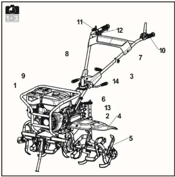

Husqvarna ^® Prod. year
Serial no.
Article no.
Model
Tilling scope
Tilling depth
Gear shifting
Engine displacement
Engine oil quality
Engine oil capacity
Gear box oil quality
Gear box oil capacity
Nominal power
Net weight
Fuel (octan/cetan)
natural_image
Technical line drawing of a mechanical device with lever and belt, no visible text or symbolsHUSQVARNA AB
SE-561 82 HUSKVARNA
SWEDEN

natural_image
Technical line drawing of a small manual tiller with a close-up inset showing the wheel rim (no text or symbols present)


natural_image
Technical line drawing of a mechanical device with no visible text or symbols

natural_image
Technical line drawing of a mechanical assembly with pipes and gears (no text or symbols)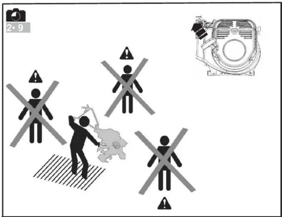


flowchart
graph TD
    A["1"] --> B["L"]
    B --> C["2"]
    C --> D["N"]
    D --> E["3"]
    E --> F["R"]
    F --> G["4"]
    G --> H["Switch mechanism"]
    H --> I["Switch switch"]
    style A fill:#f9f,stroke:#333
    style B fill:#f9f,stroke:#333
    style C fill:#f9f,stroke:#333
    style D fill:#f9f,stroke:#333
    style E fill:#f9f,stroke:#333
    style F fill:#f9f,stroke:#333
    style G fill:#f9f,stroke:#333
    style H fill:#f9f,stroke:#333
    style I fill:#f9f,stroke:#333

flowchart
graph TD
    A["Ditcher"] --> B["1 L"]
    A --> C["2 1,2"]
    A --> D["3 A,B"]
    E["Pump"] --> F["1 H"]
    E --> G["2 N"]
    E --> H["3 A,B"]
    I["Swather"] --> J["1 L"]
    I --> K["2 N"]
    I --> L["3 R"]
    I --> M["4 A,B"]
    N["Grass cutter"] --> O["1 L"]
    N --> P["2 N"]
    N --> Q["3 R"]
    N --> R["4 A,B"]
    S["Mower"] --> T["1 L"]
    S --> U["2 N"]
    S --> V["3 R"]
    S --> W["4 A,B"]
flowchart
graph TD
    A["Ditcher"] --> B["1 L"]
    A --> C["2 1,2"]
    A --> D["3 A,B"]
    E["Pump"] --> F["1 H"]
    E --> G["2 N"]
    E --> H["3 A,B"]
    I["Swather"] --> J["1 L"]
    I --> K["2 N"]
    I --> L["3 R"]
    I --> M["4 A,B"]
    N["Grass cutter"] --> O["1 L"]
    N --> P["2 N"]
    N --> Q["3 R"]
    N --> R["4 A,B"]
    S["Mower"] --> T["1 L"]
    S --> U["2 N"]
    S --> V["3 R"]
    S --> W["4 A,B"]
natural_image
Illustration of a manual lever handle with a curved blade and lever, showing motion direction (no text or symbols)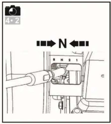
natural_image
Diagram of a mechanical device with a curved arrow indicating motion, no text or symbols present

natural_image
Mechanical assembly diagram showing a valve mechanism with no visible text or symbols
flowchart
graph TD
    A["STOP"] --> B["OFF ON"]
    B --> C["OFF"]
    C --> D["Car"]
    D --> E["A"]
    E --> F["Tot tire"]
    F --> G["Person with directional arrows"]
    G --> H["B"]
SAFETY PRECAUTIONS
Pay particular care to the sections marked as follows:

DANGER: This indicates a strong likelihood of serious or even fatal injury if the Instruction are not follow.
WARNING: This indicates a risk of injury or damage to the equipment if the instructions are not followed.
NOTE: This indicates useful information.

This symbol reminds you to take care with certain operations.
If you have any problems or questions about the tiller, please contact Husqvarna dealer.

DANGER: The machine is designed for safe and reliable service if used as instructed. Before using your machine, please make sure you have understood the contents of this manual. Otherwise you could be injured and your equipment could be damaged.
Training / Information
Familiarise yourself with the correct use and the controls before using the machine. Know how to stop the engine rapidly.
The machine must always be used according to the recommendations given in the operator manual.
Remember that the user is responsible for any accidents or dangerous actions occurring to other people or their belongings. It is users responsibility to assess the potential risks of the ground to be cleared and take all precautions necessary to ensure it is safe, in particular on slopes and on loose, slippery on uneven ground.
Never allow children or people unfamiliar with these instructions to use the machine. There may be local laws which set a minimum age for users.
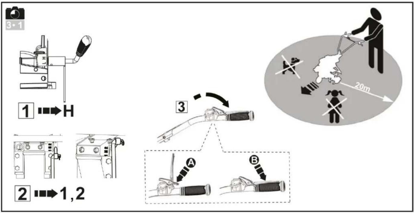
Never work when there are people, especially children, or animals within a radius of 20 meters of the machine; the operator must necessarily remain at the controls of the handles.
Do not use the machine if you have been taking medicine or other substances that might slow your reactions or make you drowsy.
Pay particular attention on hard ground, because the machine has the tendency to be much less stable than on cultivated ground.
Always wear sturdy, non-slip footwear and tight long trousers when working. Do not use the machine in bare feet or sandals. Ear protectors are recommended.
Use the machine for the purpose it is designed for tilling the ground.
Preparation
Carefully inspect the area where the machine is to be used and remove any objects that might be projected by the machine (stones, wire, glass, metal objects ...).
Before use, always inspect the machine to ensure that the tools are not worn or damaged, replace any worn or damages parts.
Maintain the electrical cables that stop the engine in good condition so that you can be sure to turn the engine off.
Check that no fuel or oil are leaking.
Do not use the machine without covers and guards and ensure that all the fittings are tight.
Use
Never transport people on the machine.
Take care when starting the engine, following the manufacturer's instructions and keeping your feet away from the blade(s).
Stop the engine when the machine is not in use.
When holding the machine, walk don't run.
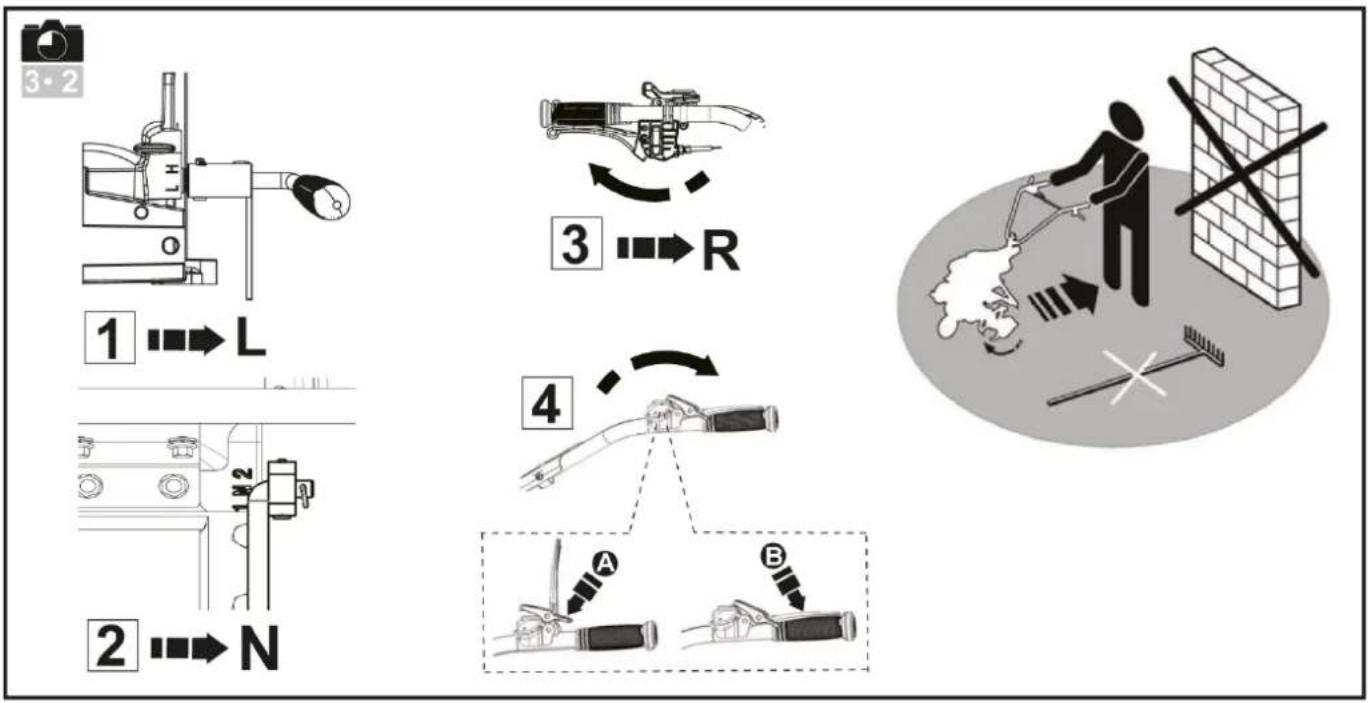
Pay close attention when pulling the machine towards you or reversing the direction of rotation (if liked).
Keep a safe distance from the rotating blades, set by length of the steering column.
Do not place you hands or feet near or beneath rotating parts.
The engine and the exhaust system become very hot during operating. Risk of burn injuries if touched.
If there is:
-abnormal vibration,
-a blockage
-a problem engaging or disengaging the clutch,
-a collision with a foreign object,
-deterioration of the engine halt cable
Stop the engine immediately (if the engine halt cable is severed. Use the starter control as described in paragraph "start the engine" to stop the engine), let the machine cool down, unplug the spark-plug lead, inspect the machine and have the necessary repairs carried out by a Husqvarna workshop before using again.
Work only by daylight or in good artificial light.
Do not use the machine on slopes greater than 20^ .
Work across the slopes, not up or down them.
Make sure to keep your feet on slopping ground, change direction very carefully.
Using accessories other than those recommended may make the machine dangerous and cause damage to your machine which will not be covered by your guarantee.
Maintenance / storage
Stop the engine before cleaning, inspecting, adjusting of maintaining the machine or changing the tool(s).
Stop the engine and use thick gloves when changing the tool(s).
Keep all nuts and bolts tight to ensure safe conditions of use.
To reduce fire risk, keep the engine, the silencer and the fuel storage area free of plants, waste oil, or any other inflammable material.
If the exhaust silencer is faulty, have it replaced, by a Husqvarna workshop.
Do not mend parts; replace them by the maker's own spares.
Replace the blades in complete sets to keep them balanced rotating.
For your own safety, do not alter the characteristic of your machine. Do not change the engine speed settings and do not run the engine at excess speeds. Regular maintenance is essential for safety and to maintain the level of performance.
Allow the engine to cool down before putting the machine away.
Danger! Fuel is highly inflammable!
Store fuel in containers specially designed for it. Always fill the tank outdoors and do not smoke while doing it.
Do not unscrew the fuel cap or top up with fuel while the engine is running or still hot.
If fuel is split on the ground do not try to start the engine; Carry the machine elsewhere and avoid all naked flames.
Store the machine in a dry place. Never store the machine in a building where the machine can reach a flame, spark or source of intense heat.
Replace the caps of the fuel tank and the fuel can correctly.
Limit the amount of fuel in the tank to reduce spillage.
Do not run the engine in a confined space where carbon monoxide vapour might accumulate.
Carbon monoxide can be fatal. Ensure good ventilation.
Moving, handling, transporting
Any action on the machine apart from ground digging must be performed with the engine stopped.
Except when (ground digging) the machine must be moved by using the transport wheel as described in "Moving" chapter.
Handling: do not try and lift the machine. The machine's weight is indicated on the type plate at the mid of this manual. Use a method of handling adapted to the weight of the machine and to the situation to guarantee the safety.
When loading or unloading the machine to or from a trailer, use a suitable ramp. Lash the machine down correctly for safe transport.
DEFINITIONS OF PICTOGRAMS

Warning
Danger
Warning
Keep safe distance
Warning
Rotating tools
Warning
Consult the Operator Manual and remove the sparkplug before performing any work
Warning
Read the Operator Manual


Throttle control

Stop switch

Ear protection must be used.
TECHNICAL INFORMATION
| TF545P | |
| Tilling width, mm | 1100 |
| Tilling depth, mm | 150 - 300 |
| Engine | WM177F/P |
| Fuel | Petrol |
| Fuel tank capacity, liters | 6,0 |
| Oil tank capacity, litre | 1,10 |
| Cylinder displacement, cm^3 | 270 |
| Max power hp (kW) @ rpm | 8,16 (6,0) @3600 |
| Gears | H, L, R, N, 2, 1 |
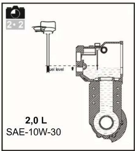
| Oil capacity gearbox, liters | 2,00 |
| Gross weight, kg | 145 |
| Net weight, kg | 130 |
| Packaging size, mm | 1030x690x850 |
IMPORTANT! When the service life of this product has been served and it is no longer used it should be returned to the dealer or to an applicable station for recycling.
IMPORTANT! We reserve the right to change specifications and designs without prior notice so as to implement improvements. Note that no legal claims are valid on the basis of information in this manual. Use only genuine parts for repairs. The warranty is not valid if non genuine parts are used.
UNPACKING/ ASSEMBLY
Note: In the constant desire to improve the products, the manufacturer states that the whole of this manual is not contractual and reserves the right to modify the specifications of the machines without notice.

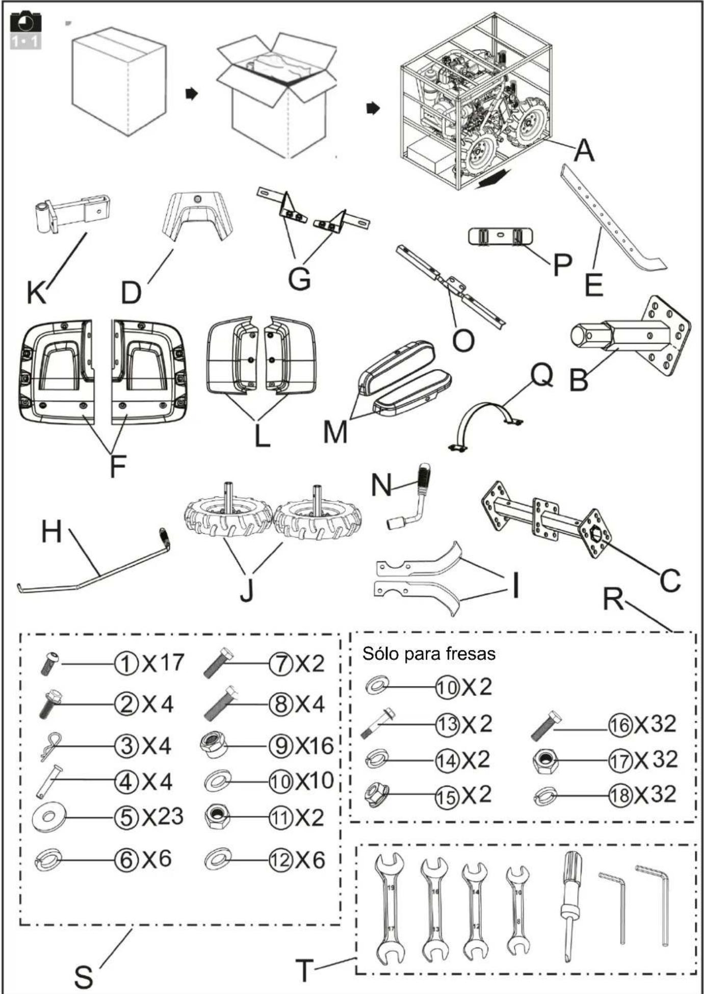
— Unpacking

WARNING:
Take care not to cut the cables or scratch the machine's paintwork when cutting the edges of the case.
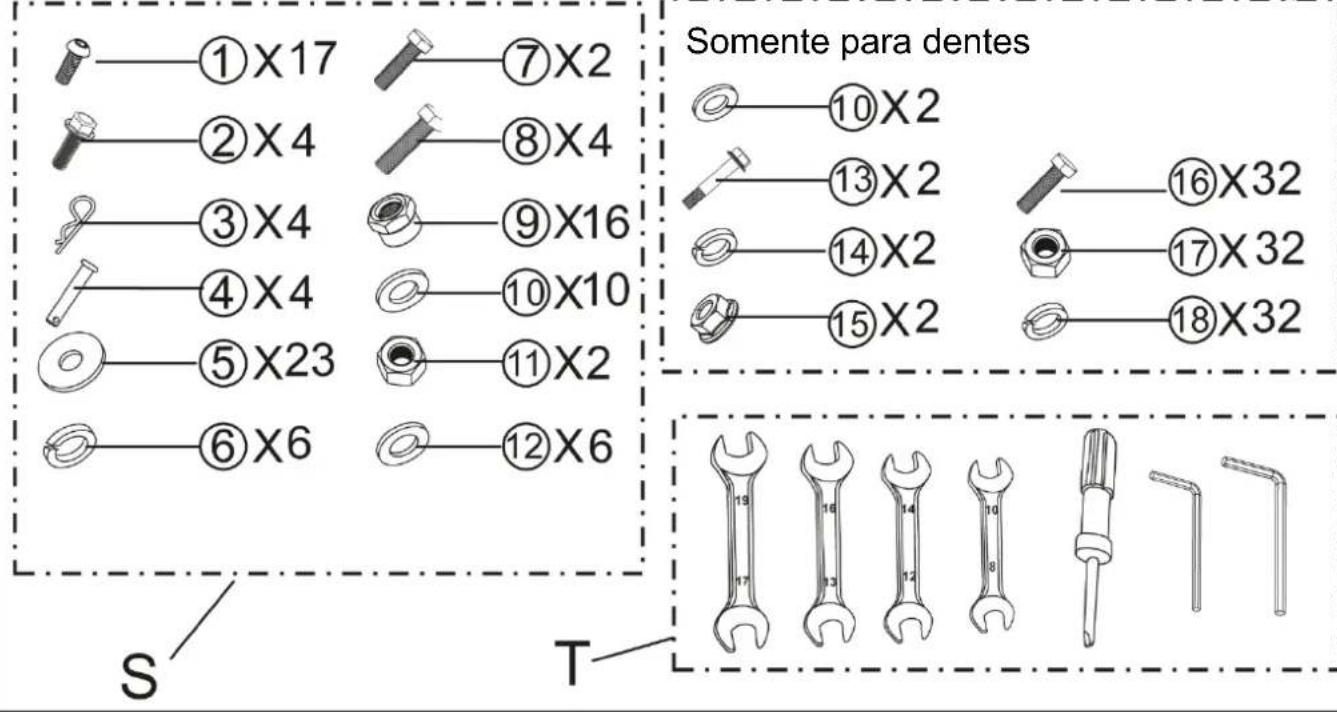
| Ref. | Contents of the case |
| A | Engine Parts |
| B | Sub Holder 1st |
| C | Holder Main Comp |
| D | Lower Tidy Cover |
| E | Drag Bar |
| F | Tine Cover |
| G | Tine Cover Bracket FR. |
| H | Lever Shifting |
| I | Blades |
| J | Wheel |
| K | Connection Joint |
| L | Extinson Cover |
| M | Side Cover |
| N | Locking Handle |
| O | Tine Cover Bracket RR. |
| P | Rubber Cable Holder |
| Q | Connecting Plate |
| R | Hardware Bag Tines only |
| S | Hardware Bag |
| T | Tool Bag |

Assembling

WARNING:
Inappropriate assembly of this rotary tiller could cause severe injuries. Ensure that you follow all the instructions carefully.

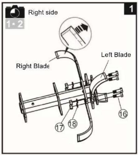
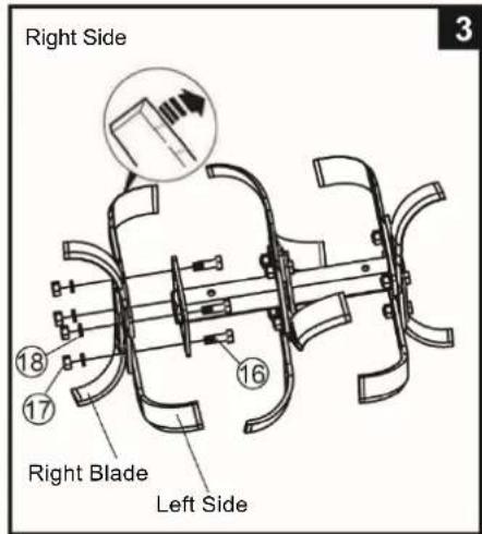
Fitting the tine blades.
Illustrations only shows assembly of the tin blades on the right side. Make sure that sharp edges face one side on both Right and Left side tines. Note: Please pay attention to distinguish the Sub Holder 1st and Sub Holder 2nd.
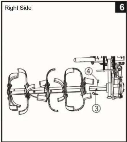
7 Fitting the connecting joint.
8 Fitting the drag bar.
9 Fitting the handle bar.
10 11 Adjusting the position of the handle bar.
12 Fitting the clutch control.
Turn to proper side and fasten the bolt.
13 14 Fitting the lower tidy cover.
- Tidy the cables,
- Put on the rubber holder properly,
- Put on the cover, and fasten with bolt.
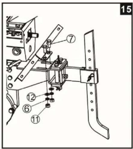
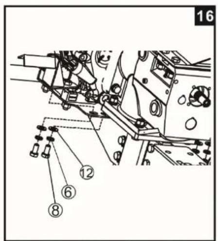
15 16 Fitting the tine cover.
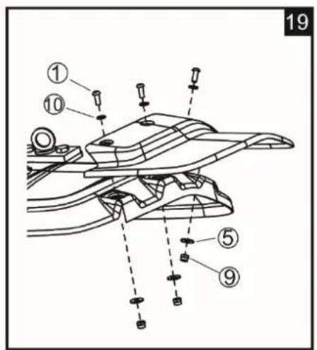
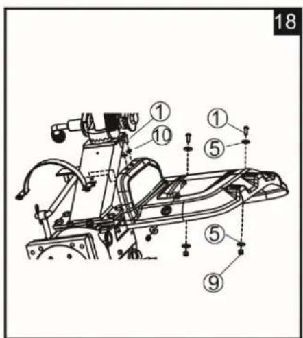
17 18 Do not tighten the bolt immediately after installed. Install all 4 bolts and nuts first, then tighten one by one.
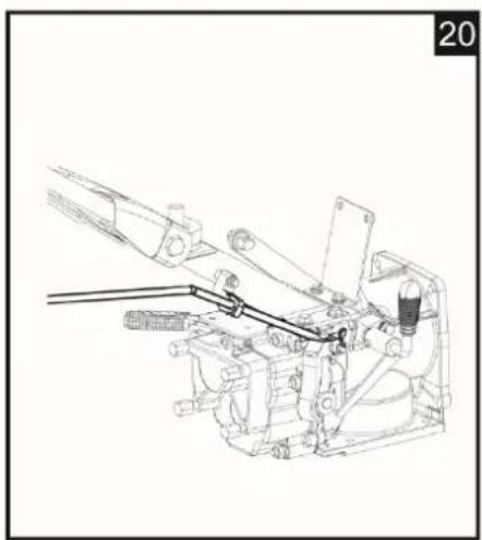
20 Fitting the shifting lever.
PTO assemble for accessories.

WARNING:
After assembling the machine completely, tighten all the bolts and screws with the moderation: do not overtighten.
Note: Any dismantling operation must only be performed by a Husqvarna workshop.

— Description of the components
1- Engine
2- Tine cover
3- Handle
4- Extension cover
5-Blades
6- Drag bar
7- Upper tidy cover
8- Lever shifting
9- Bumper
1- Clutch control
11- Throttle control
12- Reverse control
13- Side cover
14- Lower tidy cover

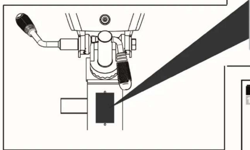
— Type plate

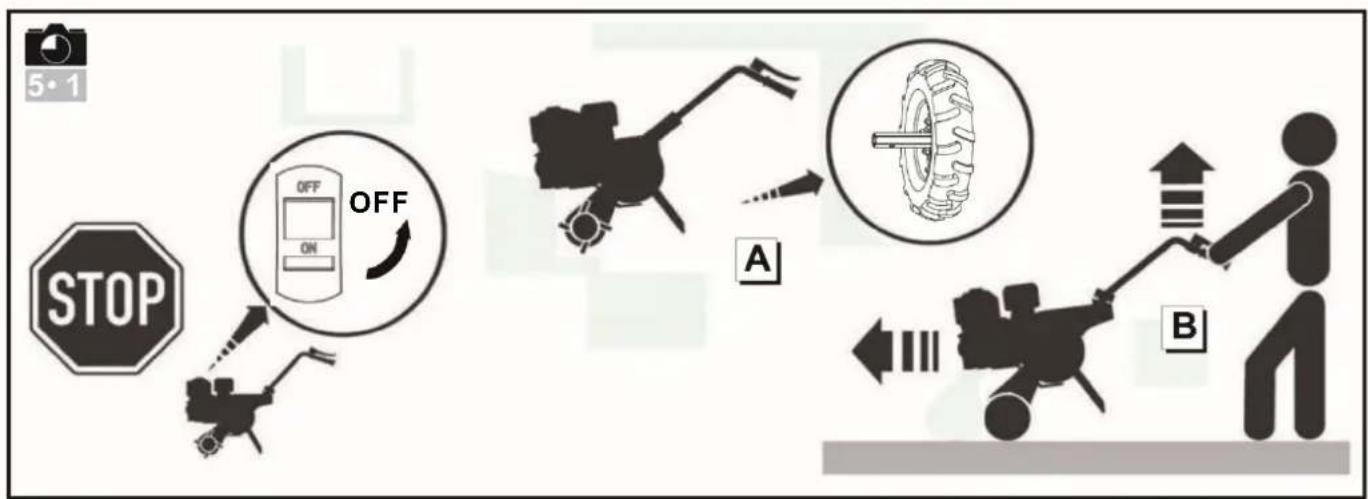
— Transport wheel
Change the blades with wheels when transporting
STARTING THE MACHINE

Filling with engine oil and checking the level

— Filling with gearbox oil

— Topping up the petrol
Recommend to USE Octane Value over 90

— Open the fuel tap

Set the choke in position A

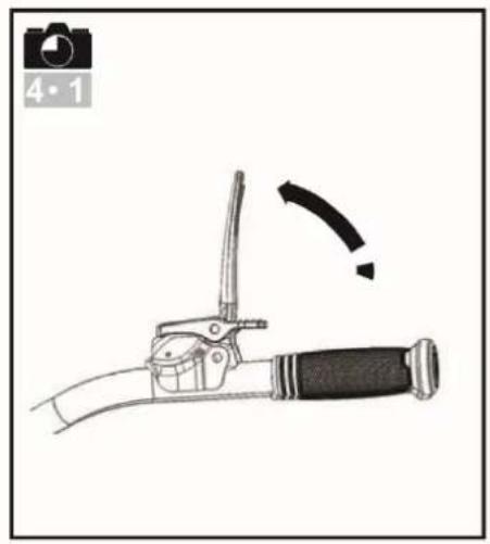
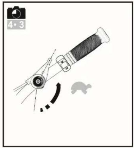
Throttle control
Put the lever to:


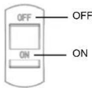
Set the on/off switch to
ON

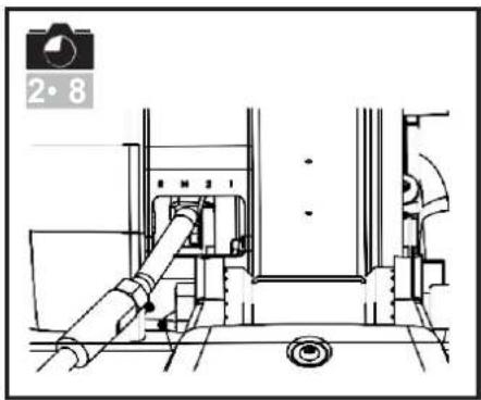
Shifting lever
Put the lever to gear N.

—— Pull the recoil start
handle

WARNING:
When the machine starts, remain within the safety zone.

Set the choke in
position B
USE


Forward

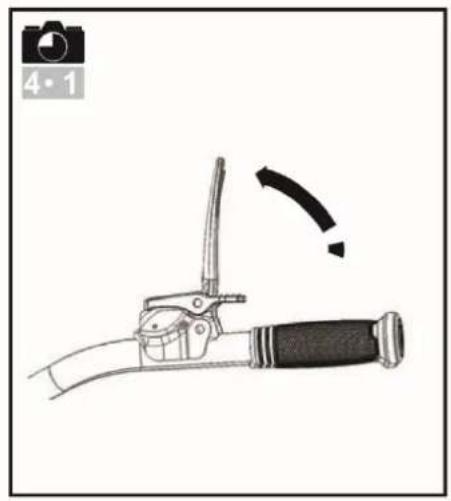
It is essential to let ou the clutch before using reverse

Maintain a safety zone of 20 m in radius around the machine


— Reverse

It is essential to let ou the clutch before using reverse

Maintain a safety zone of 20 m in radius around the machine

The use of reverse is dangerous.
Ensure that there are no obstacles behind you and reduce the engine revs begore engaging the clutch


Tiller working direction with accessories and gear control
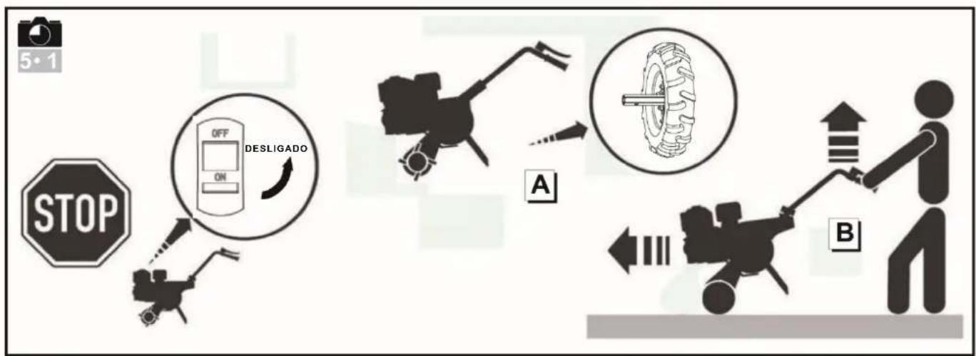
STOPPING


Stopping the rotating tools
Release the clutch lever.


shifting lever to •N•


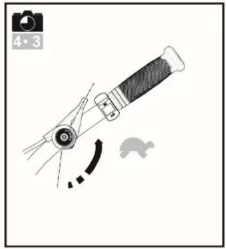
— Reduce the throttle
Set the throttle control to:


— Stopping the engine
Set the on/off switch to OFF

— Close the fuel nap
MAINTENANCE TABLE
Daily check
Before starting the engine, check the following points.
■ There must be no loosened or broken nuts or bolts.


■ Cleanliness of the air filter element

Do not use inflammable solvent to clean the foam air filter element.


■ Check lub. o level
■ N leaks of petrol or lub.


■ Sufficient petro
■ Keep the machine clean.
■ Environment protection.
■ No abnormal vibrations or excessive noise.
■ Change the lub. Oil of engine and gearbox.
Every 50 hours of every 3 months
■ Clean the air filter * (2 Fig. 4.6).
Every 100 hours or every 6 months
■ Clean the fuel filter.
■ Change the lub. Oil of engine and gearbox.
■ Clean the spark plug.
■ Clean the spark plug cap.
Every 300 hours or once a year
■ Replace the air filter *.
■ Check the play in the valve * *.
■ Replace the spark plug.
■ Clean the fuel filter * * .
■ Clean combustion chamber * * .
■ Check the fuel circuit * *.
* Clean more often in condition of use where the air is dusty or laden with aerial debris.
** Not essential except in the event of performance problems (to be conducted by a Husqvarna workshop).
For the following machinery
Product name: Gasoline powered motor hoes
Commercial name: N/A
Function: motor hoes (without driven wheels)
Type: Gasoline
Model No.: TF545P
Serial No.:
is herewith confirmed to fulfill all the relevant provisions of
Machinery Directive (2006/42/EC)
and the following harmonized standard have been complied with
EN 709: 1997 + A4: 2009
EN 709: 1997 + A4/AC:2012
is herewith confirmed to fulfill all the relevant provisions of
Electromagnetic Compatibility Directive (2014/30/EU)
and the following harmonized standard have been complied with:
EN ISO 14982: 2009
Responsible for marking this declaration is the
Manufacture's Name : Husqvarna AB
Manufacturer's Address : SE-561 82 HUSKVARNA SWEDEN
Person responsible for compiling the technical files established within the EU
Person responsible for making this declaration
Name, Surname : Claes Losdal
Position/Title : R&D Director
Place : Huskvarna
Date : 2017-12-22

Husqvarna
(Company stamp and legal signature)


natural_image
Technical line drawing of a mechanical assembly with no visible text or symbols
natural_image
Technical line drawing of mechanical assembly with no visible text or symbols
natural_image
Technical line drawing of a mechanical clamp or bracket assembly (no text or symbols)
natural_image
Diagram of a mechanical linkage system with multiple arms and directional arrows (no text or labels)
natural_image
Technical line drawing of a mechanical assembly with multiple arms and legs, no visible text or symbols
natural_image
Diagram of a bicycle steering wheel with lever mechanism and motion arrow (no text or symbols)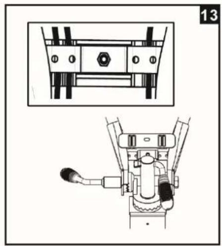
natural_image
Technical line drawing of a mechanical assembly with exploded and assembled views (no text or symbols)



natural_image
Technical line drawing of a mechanical device with lever and shaft assembly (no text or symbols)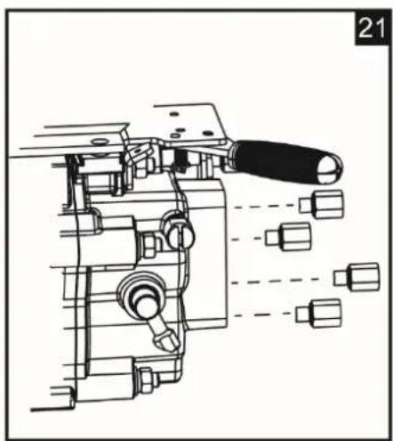
natural_image
Technical line drawing of a mechanical assembly with no visible text or symbols

Husqvarna Año prod.
N.º de serie
N.º de artículo
Modelo
Anchura de trabajo
natural_image
Technical line drawing of a mechanical device with lever and belt, no visible text or symbolsHUSQVARNA AB
SE-561 82 HUSKVARNA
SUECIA

natural_image
Technical line drawing of a tracked agricultural machine with a close-up inset showing the wheel (no text or symbols present)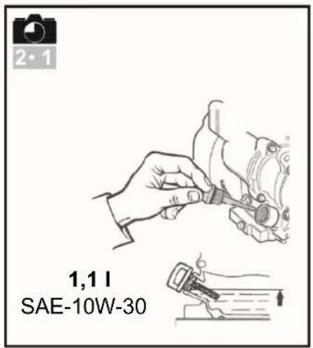


natural_image
Mechanical assembly diagram showing a valve mechanism with directional arrow (no text or symbols)

natural_image
Diagram of a mechanical device with a curved arrow indicating motion or force, no text or symbols present

natural_image
Technical line drawing of a mechanical assembly with no visible text or symbols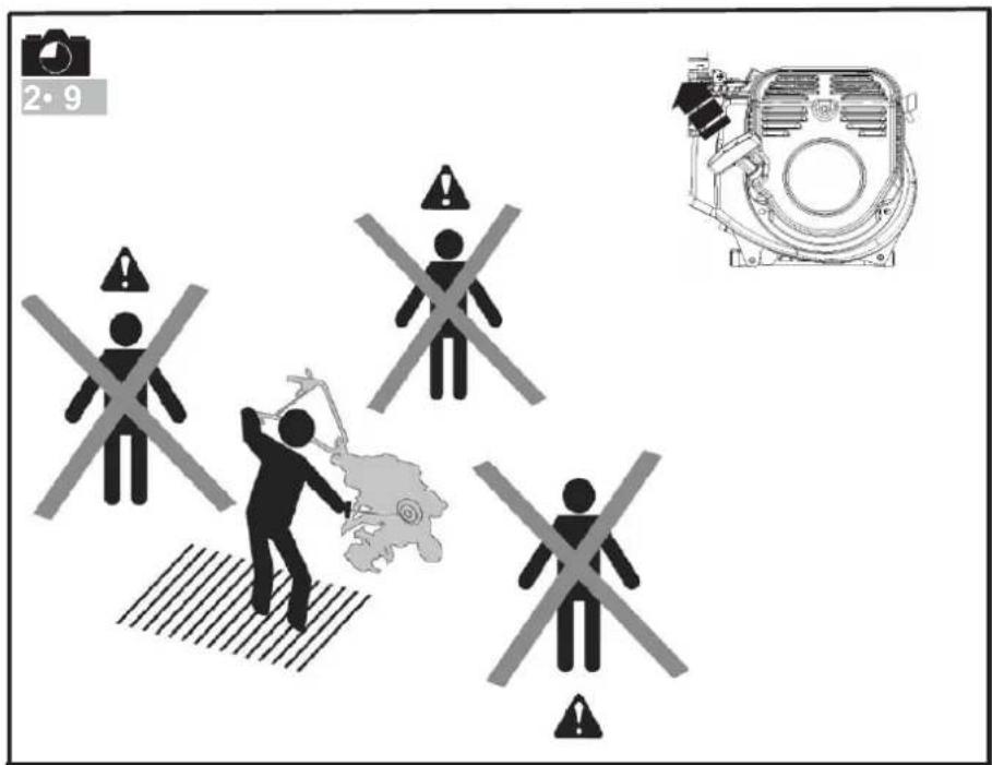

flowchart
graph TD
    A["1"] --> B["L"]
    B --> C["2"]
    C --> D["N"]
    D --> E["3"]
    E --> F["R"]
    F --> G["4"]
    G --> H["Switch mechanism"]
    H --> I["Switch symbol: A, B, C, D, E, F, G, H, I, J, K, L, M"]


natural_image
Illustration of a hand gripping a knife with a curved handle and a black grip, showing motion direction (no text or symbols)

natural_image
Diagram of a mechanical device with a curved arrow indicating motion, no text or symbols present

natural_image
Mechanical assembly diagram showing a valve mechanism with no visible text or symbols

flowchart
graph TD
    A["STOP"] --> B["OFF ON PARAR"]
    B --> C["Car with wheel"]
    C --> D["Motor with torque"]
    D --> E["Control with directional arrows"]
    style A fill:#f9f,stroke:#333
    style B fill:#ccf,stroke:#333
    style C fill:#cfc,stroke:#333
    style D fill:#fcc,stroke:#333
    style E fill:#ffc,stroke:#333
Advertencia
Peligro
Advertencia

natural_image
Technical line drawing of a mechanical assembly with no visible text or symbols
natural_image
Technical line drawing of mechanical assembly with no visible text or symbols
natural_image
Technical line drawing of a mechanical clamp or bracket assembly (no text or symbols)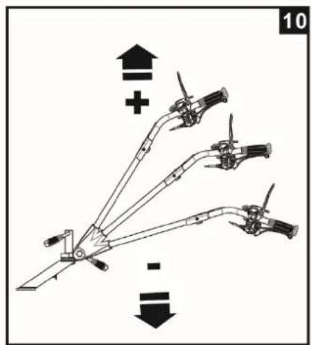
natural_image
Diagram of a mechanical linkage system with multiple arms and directional arrows (no text or labels)
natural_image
Technical line drawing of a mechanical assembly with multiple arms and legs, no visible text or symbols
natural_image
Mechanical lever diagram showing motion with a curved arrow indicating rotation (no text or symbols)
natural_image
Technical line drawing of a mechanical assembly with exploded and assembled views (no text or symbols)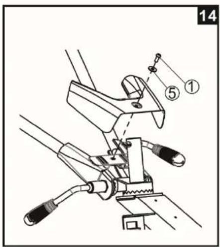




natural_image
Technical line drawing of a mechanical device with lever and shaft assembly (no text or symbols)
natural_image
Technical line drawing of a mechanical assembly with no visible text or symbols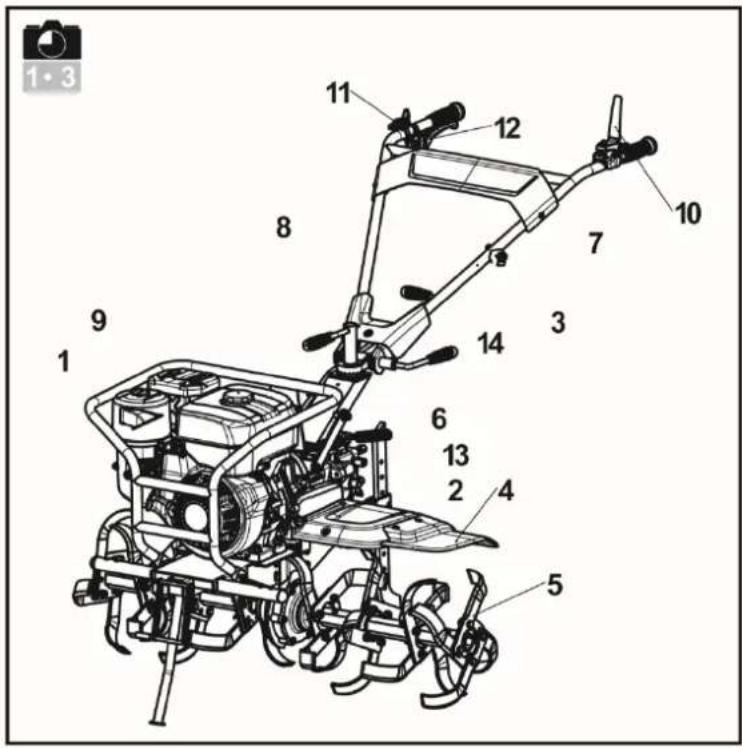

Husqvarna Ano de prod.
N° de série
Artigo n°.
Modelo
Escopo de trabalho
natural_image
Technical line drawing of a mechanical device with lever and belt, no visible text or symbolsHUSQVARNA AB
SE-561 82 HUSKVARNA
SUÉCIA

natural_image
Technical line drawing of a small manual tiller with a close-up inset showing the wheel (no text or symbols present)


natural_image
Mechanical assembly diagram showing a valve mechanism with no visible text or symbols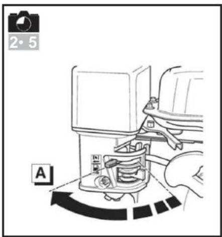

natural_image
Technical illustration of a mechanical device with no visible text or symbols
natural_image
Technical line drawing of a mechanical assembly with pipes and components (no text or symbols)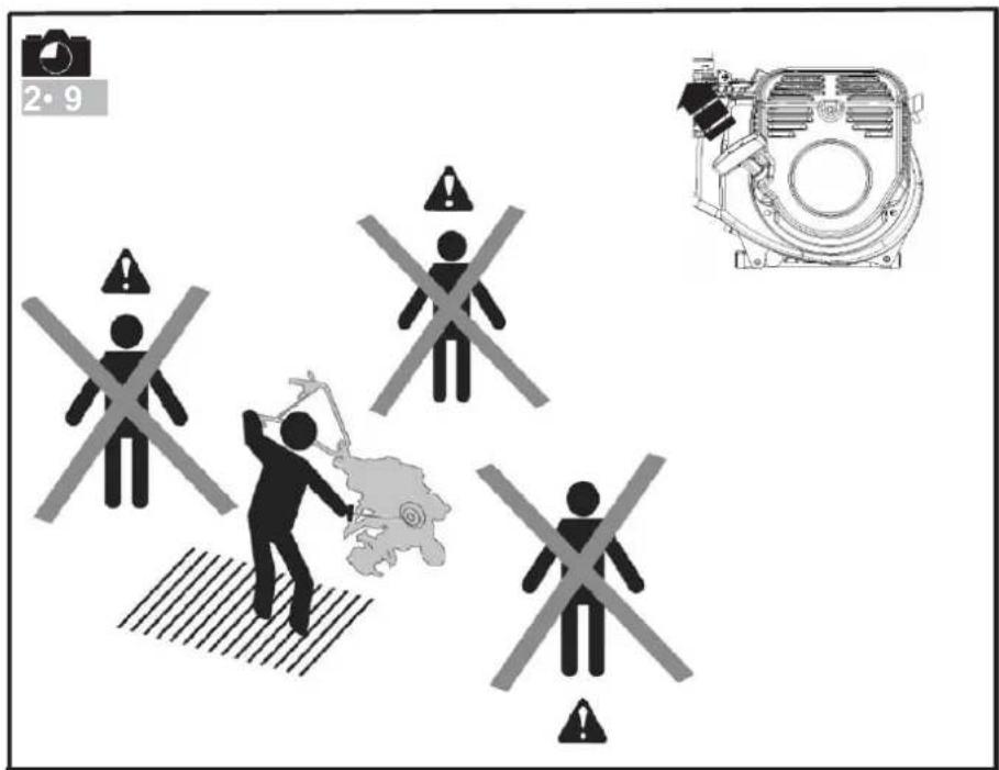


flowchart
graph TD
    A["1"] --> B["L"]
    B --> C["2"]
    C --> D["N"]
    D --> E["3"]
    E --> F["R"]
    F --> G["4"]
    G --> H["Switch mechanism"]
    H --> I["Switch switch"]
    style A fill:#f9f,stroke:#333
    style B fill:#f9f,stroke:#333
    style C fill:#f9f,stroke:#333
    style D fill:#f9f,stroke:#333
    style E fill:#f9f,stroke:#333
    style F fill:#f9f,stroke:#333
    style G fill:#f9f,stroke:#333
    style H fill:#f9f,stroke:#333
    style I fill:#f9f,stroke:#333

natural_image
Illustration of a manual lever handle with a curved blade and lever, showing motion direction (no text or symbols)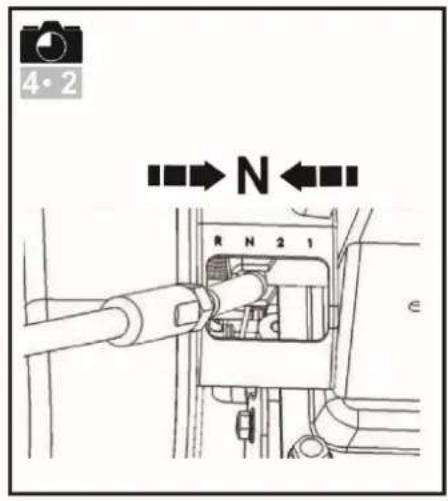
natural_image
Diagram of a mechanical device with a curved arrow indicating motion, no text or symbols present

natural_image
Mechanical assembly diagram showing a valve mechanism with no visible text or symbols
flowchart
graph TD
    A["STOP"] --> B["OFF ON"]
    B --> C["DESLIGADO"]
    C --> D["Vehicle Collision"]
    D --> E["Car Collision"]
    E --> F["Car Position"]
    style A fill:#f9f,stroke:#333
    style B fill:#ccf,stroke:#333
    style C fill:#cfc,stroke:#333
    style D fill:#fcc,stroke:#333
    style E fill:#cff,stroke:#333
    style F fill:#ffc,stroke:#333
PRECAUÇÕES DE SEGURANÇA
Original instructions


- Husqvarna ® Prod. year
- SAFETY PRECAUTIONS
- Training / Information
- Preparation
- Use
- Maintenance / storage
- Danger! Fuel is highly inflammable!
- Moving, handling, transporting
- DEFINITIONS OF PICTOGRAMS
- TECHNICAL INFORMATION
- UNPACKING/ ASSEMBLY
- — Unpacking
- WARNING:
- Assembling
- Fitting the tine blades.
- Fitting the connecting joint.
- Fitting the drag bar.
- Fitting the clutch control.
- 14 Fitting the lower tidy cover.
- 16 Fitting the tine cover.
- Fitting the shifting lever.
- — Description of the components
- — Type plate
- — Transport wheel
- STARTING THE MACHINE
- Filling with engine oil and checking the level
- — Filling with gearbox oil
- — Topping up the petrol
- — Open the fuel tap
- Set the choke in position A
- Throttle control
- Set the on/off switch to
- Shifting lever
- —— Pull the recoil start
- handle
- Set the choke in
- position B
- Forward
- — Reverse
- STOPPING
- MAINTENANCE TABLE
- Daily check
- Every 50 hours of every 3 months
- Every 100 hours or every 6 months
- Every 300 hours or once a year
- For the following machinery
- Husqvarna Año prod.
- Advertencia
- Husqvarna Ano de prod.
- PRECAUÇÕES DE SEGURANÇA
Brand : HUSQVARNA
Model : TF 545P
Category : Milling machine