
Gentex GENFDM3LN - Dashboard camera AUDIOVOX - Free user manual and instructions
Find the device manual for free Gentex GENFDM3LN AUDIOVOX in PDF.


| Product Type | Dashboard Camera |
| Brand | Audiovox |
| Model | Gentex GENFDM3LN |
| Dimensions | Approx. 2.2 x 1.9 x 1.2 inches (55 x 48 x 30 mm) |
| Weight | Approx. 2.1 oz (60 g) |
| Power Supply | DC 12V via included car cigarette lighter adapter |
| Battery | Built-in rechargeable Li-ion (200 mAh) |
| Display | 2.0-inch TFT LCD |
| Video Resolution | Full HD 1080p (1920x1080) at 30 fps |
| Field of View | 120° wide angle |
| Night Vision | Yes, with infrared LEDs |
| Loop Recording | Yes, continuous recording in selectable segments |
| G-Sensor | Built-in, automatically locks video on impact |
| Motion Detection | Yes, starts recording when motion is detected |
| Storage | MicroSD card up to 32 GB (Class 10 recommended) |
| Built-in Microphone | Yes, for audio recording |
| Mounting | Suction cup mount for windshield |
| Operating Temperature | 14°F to 140°F (-10°C to 60°C) |
| Languages | English, French, Spanish (and others) |
| Certifications | FCC, CE |
| Accessories Included | Car charger, USB cable, suction mount, user manual |
| Care Instructions | Clean lens with soft microfiber cloth; avoid prolonged exposure to direct sunlight |
Frequently Asked Questions - Gentex GENFDM3LN AUDIOVOX
User questions about Gentex GENFDM3LN AUDIOVOX
0 question about this device. Answer the ones you know or ask your own.
Ask a new question about this device
Download the instructions for your Dashboard camera in PDF format for free! Find your manual Gentex GENFDM3LN - AUDIOVOX and take your electronic device back in hand. On this page are published all the documents necessary for the use of your device. Gentex GENFDM3LN by AUDIOVOX.
USER MANUAL Gentex GENFDM3LN AUDIOVOX
natural_image
Line drawing of a rectangular object with a small protrusion at the base (no text or symbols)Congratulations and thank you for purchasing a Gentex brand Full Display Mirror (FDM®). This intelligent rear vision kit consists of a unique display-integrated mirror and custom-designed camera engineered specifi cally for automotive rear vision.
Tools required


natural_image
Line drawings of three different wrenches and a flat plate, no text or symbols present1

natural_image
Line drawing of a hand using pliers to press or install a component on a table (no text or symbols)Turn car off. Remove the negative battery cable and safely tuck cable out of the way.
2
natural_image
Line drawing of a mechanical component with a cylindrical shaft and flange (no text or symbols)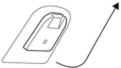
natural_image
Simple line drawing of a rectangular basin with an arrow indicating upward direction (no text or symbols)Remove the factory mirror from the windscreen.
Most mirrors are removed by loosening the T20 Torx screw on the mirror base and sliding mirror upward towards the headliner.
*Mirror removal process may vary by vehicle.
3

natural_image
Line drawing of a hand holding a curved object with an arrow indicating direction (no text or symbols)If needed, remove body panels for mirror and camera installation. For example, the a-pillar may require removal as shown above.
4
natural_image
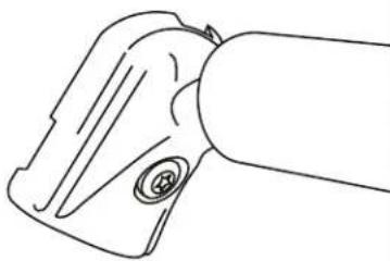
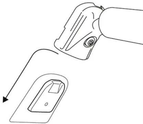
Line drawing showing a mechanical component being processed into a sink, with no text or symbols present.Mount the Full Display Mirror on the windshield by sliding the mirror mount over the button. Tighten the T20 Torx set screw to 13.3 - 17.7 in-lbs.
*Specific vehicle adaptors may be needed.


9
Mirror Harness Vehicle Harness
natural_image
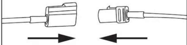
Diagram showing two types of electrical connectors with bidirectional arrows indicating connection (no text or symbols)Plug the longest piece of coax harness into the female coax connector coming from the mirror. Wrap a piece of foam tape around connectors to prevent rattle.
10
natural_image
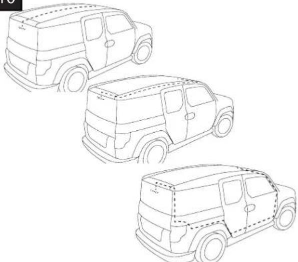
Line drawings of three different van models with open doors, shown from top to bottom (no text or symbols)Route long piece of coax harness to camera mounting location. Secure coax harness along route with foam tape and/or cable ties. *If 90 degree connector cannot reach camera, another length of coax wire (purchased separately) can be used as an extension. The maximum recommended overall coax length is 30ft. It is also recommended to use cable ties every 150mm and within 30mm of a connector. Only use the 90 degree connector to plug into camera.
11
Camera Harness Vehicle Harness

natural_image
Diagram showing two connected electrical connectors with arrows indicating direction of change (no text or symbols)Plug shorter piece of coax harness into the long piece of coax harness. Wrap a piece of foam tape around connectors to prevent rattles. Ensure 90 degree connector can reach camera location. Secure harness along route with foam tape or cable ties.
12
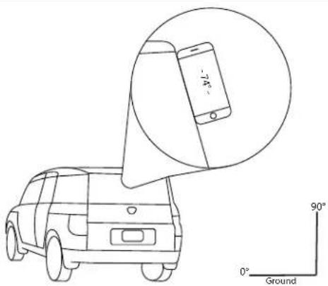
Choose camera mounting location inside the vehicle. Measure the angle at location chosen. Most smart phones have a built in angle fi nder.
Tips!
Final mounting position of camera should be located as high as possible.
Final mounting position of camera should be in between defrost lines and in wiper path, if possible to ensure unobstructed view.
Final mounting position of camera should be in center of vehicle. Do not place camera on sliding or moving glass.
Camera should only be mounted inside of vehicle.
13
17irc-29irc30irc-54irc55irc-90irc

natural_image
Line drawings of various plastic containers and buckets, including a conical container and three empty buckets with different internal designs (no text or symbols)Choose appropriate window bracket for angle measured.
Examples:
17°-29° - Sports Cars/ Sedans
30irc-54irc-CUVs
55°-90° - SUVs/ Trucks
14

natural_image
Line drawing of a hand cleaning a cloth with spray bottle (no text or symbols)Clean both interior and exterior of glass of mounting location. Ensure interior of glass is dry and debris free to ensure best foam adhesion during camera installation.
15

Install camera into window bracket (measured for vehicle). Do NOT take off two way tape liner.
16

Screw in both T-10 camera set screws provided (one on each side). Do NOT tighten.
17

natural_image
Technical line drawing of a mechanical device with attached cable and connector (no text or symbols)Plug the 90-degree coax cable into the camera.
Only the 90-degree cable can be used to plug into the camera!
18
natural_image
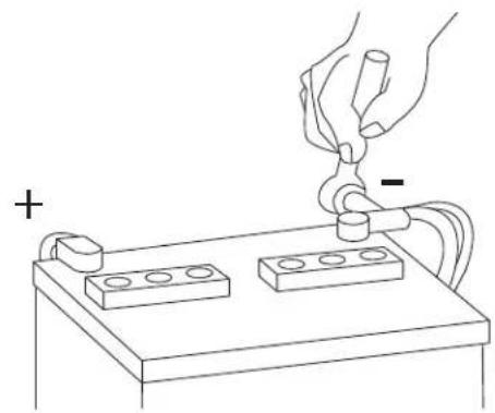
Line drawing of a hand using a tool to lift a component on a battery (no text or symbols)Reconnect the negative battery cable.
19

natural_image
Line drawing of a hand holding a rectangular object with a curved arrow indicating rotation (no text or symbols)Toggle lever back towards rear of vehicle to place mirror in display mode.
20

natural_image
Line drawing of a hand holding a small electrical socket (no text or symbols)Do NOT take off two way tape liner. Hold camera bracket with camera to mounting location to test location chosen. Dry fit camera in location.
Tips!
Ensure camera cover does not interfere with vehicle interior. Ensure coax cable can reach and can be tucked out of the way.
21

natural_image
Diagram of a vehicle on a road with traffic lights and exhaust plumes, enclosed in a rounded rectangular frame (no text or symbols)Do NOT take off two-way tape. With vehicle ignition on and mirror in display mode, aim the camera. Choose location that image looks best in mirror display.
Tips!
Ensure camera image is level.
Ensure camera can point at horizon.
22
natural_image
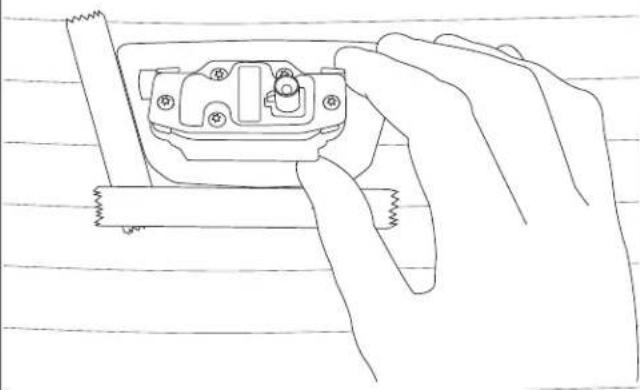
Line drawing of a hand holding a small electrical component with wires attached (no text or symbols)Using masking tape, mark the location at which you would like to mount the camera.
23
natural_image
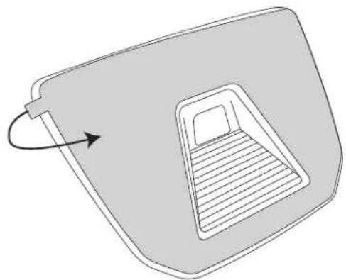
Diagram of a door handle with an arrow indicating clockwise motion (no text or symbols)Double check the mounting location is correct. Remove two-way tape liner. Ensure debris or hand oils do not get on two-way tape.
24

1 Minute

natural_image
Line drawing of two hands assembling a small mechanical component (no text or symbols)Caution!
Adhesive is difficult to remove. If done incorrectly, a new bracket and adhesive is recommended.
In mounting location, place window bracket onto rear glass. Press, hold, and apply even pressure across the entire surface. Press and hold for 1 minute. Install temp should be above 50 degrees fahrenheit.
25

Adjust camera up or down on the window bracket so the image (in display mode) has the horizon in the upper third of the mirror. Tighten both set screws on camera mounting bracket. Do not over tighten.
26

natural_image
Simple line drawing of a mechanical component with a curved rod and arrow indicating rotation (no text or symbols)Install camera cover. Secure camera cover with the two T-15 screws provided. Do not over tighten.
27
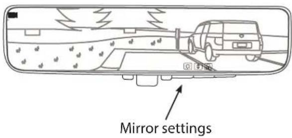
Adjust camera image using mirror settings. Adjust the tilt up or down so the image is centered. The image may still appear rotated, however the product is equipped with an auto rotate feature. You will notice the screen shift periodically for the first 30-60 minutes of driving. After that time the image will be level. Please refer to quick reference guide for full menu instructions.
28
natural_image
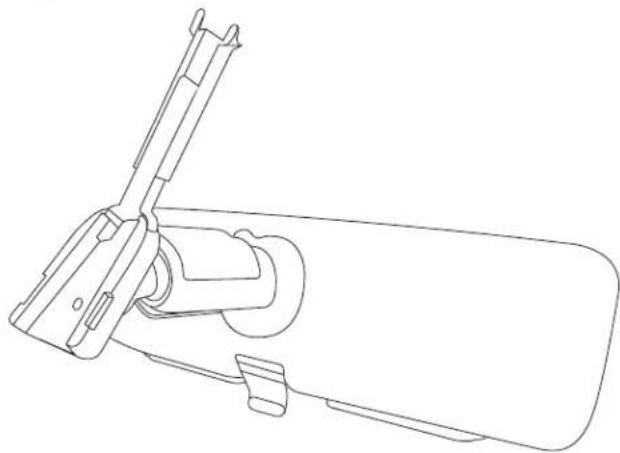
Line drawing of a mechanical device with no visible text or symbolsInstall the wire cover over the two harnesses by seating the bottom of the cover into the mirror mount and then sliding the top of the cover up to the headliner.
29
natural_image
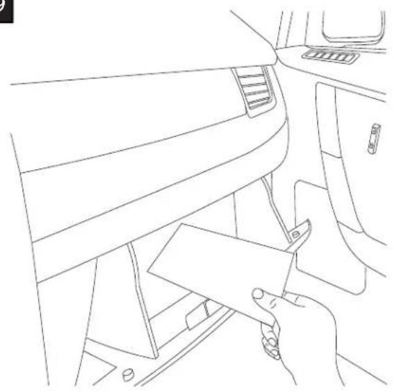
Line drawing of a car interior showing the dashboard and seat area with hand holding a folder (no text or symbols)Place paper product (quick reference guide) in the glove box.
30

natural_image
Line drawing of a rectangular device with a handle and internal components, no text or symbols present
If you would like to add a secondary camera via NTSC input you will need to activate the mirror's secondary camera display. To do this, flip the toggle switch to mirror mode. Then, hold the farthest button to the right for 23-27 seconds. An image will display indicating the RCD display is now active. This secondary NTSC input is triggered by 12v to pin 8.
31 Testing Auto-dimming Function

flowchart
graph TD
    A["Object"] --> B{Color Mapping}
    B --> C["Color Package"]
    C --> D["Packaging"]
To test dimming function, toggle lever forward towards windshield to place in mirror mode.
While in mirror mode, using a dark cloth or cardboard, completely cover forward-looking sensor. Mirror will dim after a few seconds (depending on light conditions).
Finally, adjust the mirror to standard driving position and toggle lever back towards rear of vehicle to place in display mode. Camera image will appear in mirror.
Connector Pin Out
| Cav | Circuit | Color |
| 1 | 12v PWR | RED |
| 2 | GROUND | BRN |
| 3 | - | - |
| 4 | - | - |
| 5 | NTSC(+) | PUR |
| 6 | NTSC(-) | ORG |
| 7 | - | - |
| 8 | 12v NTSC Signal | GRY |
| 9 | Exterior Mirror(-) | BLK |
| 10 | Exterior Mirror(+) | WHT |
| 11 | Camera PWR | BLU |
| 12 | - | - |

THE GENTEX
FULL DISPLAY MIRROR®
Operation Display Adjustments
- Mirror Mode: After installation and before driving, place the FDM in mirror mode by pushing the toggle switch at the base of the mirror away from the driver (toward the windshield). Adjust the mirror as necessary for proper vision out of the rear window.
- Display Mode: To activate display mode, pull the toggle switch toward the driver. This illuminates the display to provide a real-time, wide-angle video feed from the rearward-facing camera.
- Reverse Mode (if equipped): To activate reverse view, place vehicle in reverse. This switches to reverse view to provide a real-time view of the area behind your vehicle.
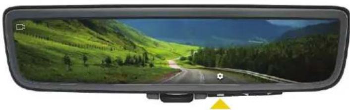
Display Mode: To activate display mode, pull the toggle switch toward the driver. This illuminates the display to provide a real-time, wide-angle video feed from the rearward-facing camera. Activate the display menu by pressing “Select” while in display mode. Pressing “Select” one or more times will navigate through the menu options to the right.
Note: Changes may not be saved if the FDM is switched to mirror mode.
Warning: The menus may block visibility. It is not recommended to use the menu to change settings unless the vehicle is OFF or in PARK.
Operation
Mirror Display

natural_image
Top-down view of a black rectangular rear mirror with a yellow triangular pointer at the base (no text or symbols visible)Push toward the windshield Pull toward the driver

natural_image
Viewfinder rear mirror displaying a scenic mountain road through green hills and trees (no text or symbols visible)Display Adjustments
Select Brightness
natural_image
Viewfinder rear mirror displaying a scenic mountain road through green hills and forested valleys (no text or symbols visible)Camera angle Color intensity

natural_image
Viewfinder rearview mirror displaying a scenic mountain road through green hills and forested valleys (no text or symbols visible)Move the camera image displayed in the mirror up and down

natural_image
Viewfinder rear mirror displaying a scenic mountain road through green hills (no text or symbols visible)Change the display brightnessActivate "Select"

natural_image
Viewfinder rear mirror displaying a scenic mountain road through green hills, with no visible text or symbols on the road or background.Change the intensity of red and blue color levels in the display (this feature can compensate for vehicles with window tint)
Troubleshooting
Mirror shows the video display and reflection of vehicle interior. Mirror has excessive glare in display mode.
Switch mirror back into mirror mode by pushing toggle switch forward. Then readjust mirror head so that driver has a clear rearward view. When placed back into display mode, the mirror head will be tilted upward, removing the interior reflection.
Mirror display is hazy, gray, or foggy.
Check rear glass to ensure it is clean. During certain weather conditions the rear vehicle glass can become foggy with condensation. Switch to mirror mode until camera view is clear again. Turning on the rear defroster will usually solve this issue.
Mirror display appears obstructed or out of focus.
Switch to mirror mode until it is safe to examine the camera and rear of vehicle for obstructions, dirt, water droplets, etc.
Mirror display appears grainy at nighttime.
In order to display the best possible image, the camera will automatically adjust its frame rate during dark conditions. A lower frame rate can make the display appear grainy. The camera is still operating as intended.
36 MONTH LIMITED WARRANTY
Voxx Electronics Corporation (the Company) warrants to the original purchaser of this product that should this product or any part thereof, under normal use and conditions, be proven defective in material or workmanship within 36 months from the date of original purchase, such defect(s) will be repaired or replaced with new or reconditioned product, (at the Company's option) without charge for parts or repair labor. A transmitter for a vehicle security or remote start system is warranted for 12 months from the date of original purchase.
To obtain repair or replacement within the terms of this Warranty, the product is to be delivered with proof of warranty coverage (e.g. dated bill of sale), authorization number, specification of defect(s), transportation prepaid, to an approved warranty station. This warranty is not transferable.
This Warranty does not cover damage to the vehicle's electrical system or costs incurred for the installation, removal or reinstallation of the product. This Warranty does not cover batteries, broken LCD transmitter display screens, nor apply to any product or part thereof which, in the opinion of the Company, has suffered or been damaged through alteration, improper installation, mishandling, misuse, abuse, neglect, accident, or by removal or defacement of the factory serial number/bar code label(s).
This Warranty is in lieu of all other express warranties or liabilities. ANY IMPLIED WARRANTIES, INCLUDING ANY IMPLIED WARRANTY OF MERCHANTABILITY, SHALL BE LIMITED TO THE DURATION OF THIS WRITTEN WARRANTY. ANY ACTION FOR BREACH OF ANY WARRANTY HEREUNDER INCLUDING ANY IMPLIED WARRANTY OF MERCHANTABILITY MUST BE BROUGHT WITHIN A PERIOD OF 24 MONTHS FROM DATE OF ORIGINAL PURCHASE. IN NO CASE SHALL THE COMPANY BE LIABLE FOR ANY CONSEQUENTIAL OR INCIDENTAL DAMAGES FOR BREACH OF THIS OR ANY OTHER WARRANTY. No person or representative is authorized to assume for the Company any liability other than expressed herein in connection with the sale of this product.
The company does not warrant that this product cannot be compromised or circumvented. THE EXTENT OF THE COMPANY'S LIABILITY UNDER THIS WARRANTY IS LIMITED TO THE REPAIR OR REPLACEMENT PROVIDED ABOVE AND, IN NO EVENT, SHALL THE COMPANY'S LIABILITY EXCEED THE PURCHASE PRICE PAID BY PURCHASER FOR THE PRODUCT WITHOUT INSTALLATION LABOR.
Some states do not allow limitations on how long an implied warranty lasts or the exclusion or limitation of incidental or consequential damage so the above limitations or exclusions may not apply to you. This Warranty gives you specific legal rights and you may also have other rights which vary from state to state.
Voxx Electronics Corporation, 2351 J. Lawson Blvd., Orlando, Florida 32824

ongratulations and thank you for purchasing a Gentex brand Full Display Mirror (FDM®). This intelligent rear vision kit consists of a unique display-integrated mirror and custom-designed camera engineered specifically for automotive rear vision.
The FDM offers bimodal functionality. In mirror mode, it functions as a standard auto-dimming rearview mirror. But with the flip of the toggle switch, the mirror enters display mode, and a clear, bright, LCD display appears through the mirror's reflective surface, providing a wide, unobstructed rearward view. While in mirror mode during nighttime driving, the FDM also automatically detects glare from trailing vehicle headlights and darkens to the precise level necessary to eliminate the glare and preserve driver vision.
GENTEX CORPORATION

natural_image
Abstract geometric pattern composed of black squares and lines on white background (no text or symbols)
© 2019 Gentex Corporation
Gentex®, Full Display Mirror® and FDM® are all trademarks of Gentex Corporation.
GENTEX
CORPORATION
A Smarter Vision®
BY INSTALLING AND/OR USING THIS PRODUCT YOU ARE AGREEING TO THE TERMS AT:
www.gentex.com/aftermarket-terms

550-0737 Rev AAA

Brand : AUDIOVOX
Model : Gentex GENFDM3LN
Category : Dashboard camera