
Voxx VXMTG13 - Dashboard camera AUDIOVOX - Free user manual and instructions
Find the device manual for free Voxx VXMTG13 AUDIOVOX in PDF.


| Product Type | Dashboard Camera |
| Brand | Audiovox |
| Model | Voxx VXMTG13 |
| Dimensions (approx.) | 2.5 x 1.5 x 1.2 inches (63 x 38 x 30 mm) |
| Weight (approx.) | 2.1 oz (60 g) |
| Power Supply | 12V DC via cigarette lighter adapter |
| Battery | Built-in rechargeable lithium-ion battery (approx. 200 mAh) |
| Video Resolution | Full HD 1080p (1920 x 1080) at 30 fps |
| Field of View | 140° wide angle lens |
| Loop Recording | Yes, overwrites oldest files |
| G-Sensor | Built-in for impact detection and automatic file protection |
| Night Vision | Infrared LEDs for low-light recording |
| Display | 2.0 inch TFT LCD screen |
| Storage | MicroSD card (up to 32 GB, Class 10 recommended) |
| Mounting | Suction cup mount for windshield |
| Care and Cleaning | Wipe lens with soft, dry cloth; avoid liquids |
| Safety | Do not obstruct driver's view; ensure secure mounting |
| Spare Parts and Repairability | Contact Audiovox support for replacement mounts or chargers; non-user-serviceable internal battery |
| General Information | Operating temperature: -10°C to 60°C; language support: English |
Frequently Asked Questions - Voxx VXMTG13 AUDIOVOX
User questions about Voxx VXMTG13 AUDIOVOX
0 question about this device. Answer the ones you know or ask your own.
Ask a new question about this device
Download the instructions for your Dashboard camera in PDF format for free! Find your manual Voxx VXMTG13 - AUDIOVOX and take your electronic device back in hand. On this page are published all the documents necessary for the use of your device. Voxx VXMTG13 by AUDIOVOX.
USER MANUAL Voxx VXMTG13 AUDIOVOX
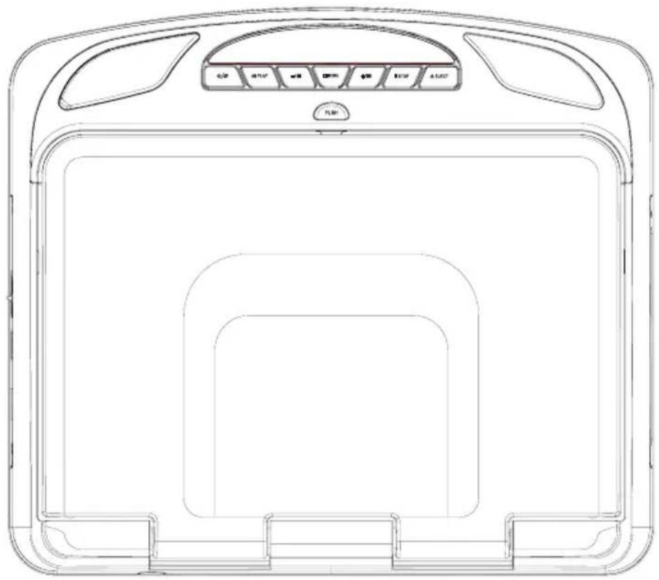
13.3" Overhead LCD Monitor With Built-In DVD Player Installation Guide

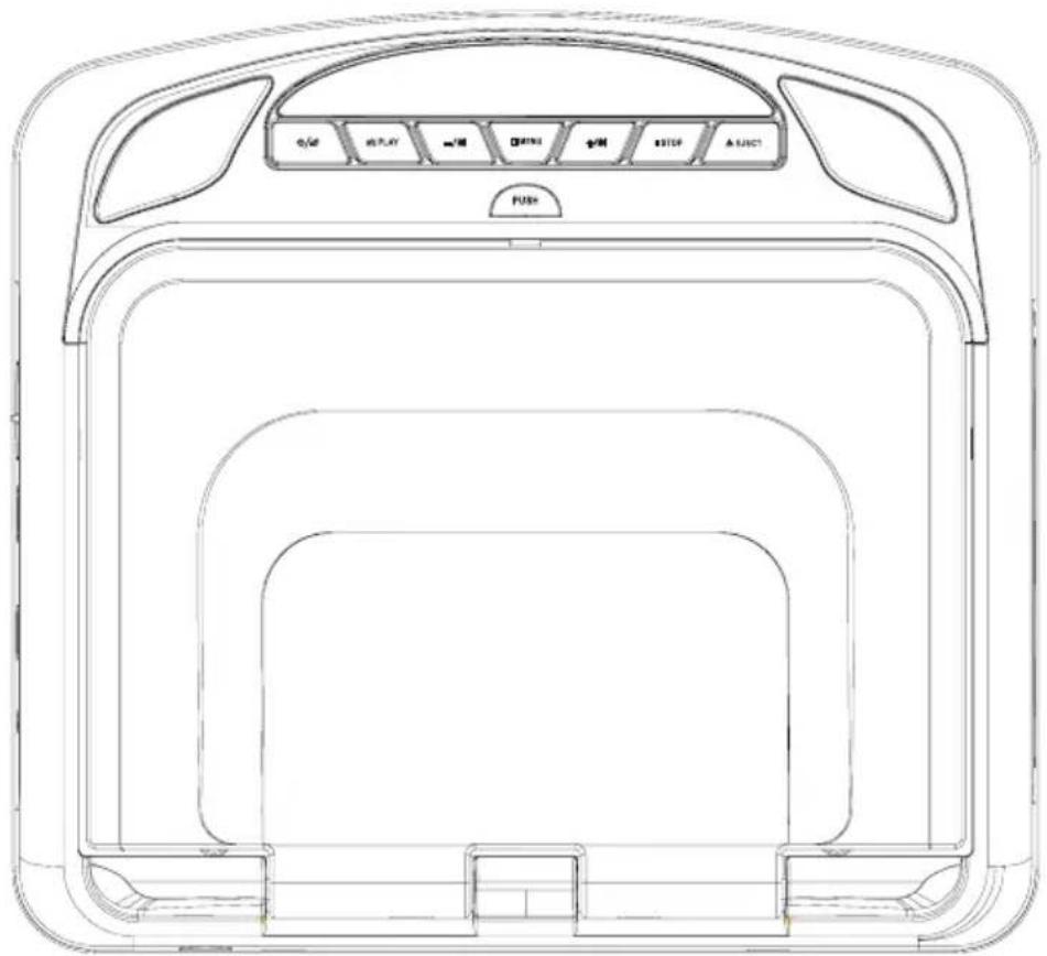
Installation of overhead products requires careful planning and preparation. Be extremely careful when working on a vehicle with side curtain air bags. Do not route wires near any portion of the side curtain air bag assemblies. This includes any anchor points in A, B, C or D pillars of the vehicle. Routing wires in these areas or running wires by the side curtain air bags can prevent the side curtain air bag from fully deploying which can result in personal injury to vehicle occupants. If you have any questions regarding wire routing in a vehicle, please contact Audiovox Technical Support at 1-800-225-6074.
When connecting power and ground in a mobile video installation, ensure that the ACC wire is fused at the point where it is connected to the vehicle ACC wiring. Failure to do so can result in damage to the vehicle if a short circuit develops between the vehicle connection point and the mobile video product.
An LCD panel and/or video monitor may be installed in a motor vehicle and visible to the driver if the LCD panel or video monitor is used for vehicle information, system control, rear or side observation or navigation. If the LCD panel or video monitor is used for television reception, video or DVD play, the LCD panel or video monitor must be installed so that these features will only function when the vehicle is in “park” or when the vehicle's parking brake is applied.
An LCD panel or video monitor used for television reception, video or DVD play that operates when the vehicle is in gear or when the parking brake is not applied must be installed to the rear of the driver's seat where it will not be visible, directly or indirectly, to the operator of the motor vehicle.
Warnings
- Do not use any solvents or cleaning materials when cleaning the video monitor.
- Do not use any abrasive cleaners, they may scratch the screen.
Use only a lightly dampened lint free cloth to wipe the screen if it is dirty.
Lock the LCD screen in the fully closed position when not in use.
Before putting on headphones always adjust the volume setting to the lowest position.
Remember to leave the dome light switch in the off or auto positions when the vehicle is unattended, as the dome lights, if left on, can drain the vehicle's battery.
Do not put pressure on the screen.
Caution children to avoid touching or scratching the screen, as it may become dirty or damaged.
Safety Precaution
For safety reasons, when changing video media, it is recommended that the vehicle is not in motion, and that you do not allow children to unfasten seat belts to change video media or make any adjustments to the system. System adjustments can be accomplished using the remote control, while seat belts remain fastened. Enjoy your entertainment system but remember the safety of all passengers remains the number one priority.
Table Of Contents
Materials Include In This Package....5
Installing The Unit In A Vehicle....7
Installing The Snap-On Shroud 8
Installing The Snap-On Screen Cover....9
Installing The Trim Ring....10
General Vehicle Installation Approach ....11
Vehicle Preparation....12
Connecting The Dome Lights....13
Installing The Mounting Bracket....15
Installing The Unit Video System- Wiring Diagram 16
Installing The Unit Video System- Mounting The Unit......18
Appendix A - Removing The Screen Back Cover....19
Appendix A - Removing The Trim Ring and Shroud ......20
Appendix B - Installing The Optional Thick Trim Ring......21
Troubleshooting 22
Materials Included In This Package
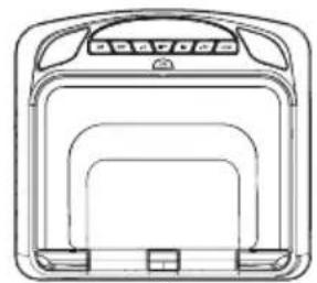
natural_image
Line drawing of a rectangular device with internal compartments and control panel (no text or symbols)1

2

3
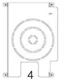
natural_image
Pure technical diagram of a circular component with concentric rings and mounting holes, no text or symbols present.[Non-Text]
5

6

7

8

natural_image
Empty rectangular frame with rounded corners and corner markers (no text or symbols)9

natural_image
Simple line drawing of three stacked rectangular shapes with rounded corners (no text or symbols)10

natural_image
Simple line drawing of a rectangular frame with rounded corners and two small side connectors at the bottom (no text or symbols)11
- 13.3" TFT LCD Overhead Monitor with DVD Player - (1 pc)
- Hardware Package (P/N 540-017) - (1 pkg)
M3 x 5mm Phillips Screws - (12 pcs)
8 x 3/8" Self Drilling Screws - (4 pcs)
M5 x 10mm Phillips Screws - (4 pcs)
M5 x 20mm Phillips Screws - (4 pcs)
M5 x 40mm Phillips Screws - (4 pcs)
Pry Tool and Slide Knob for Dome Light Switch (P/N 540-018) - (1 pc)
CAUTION: The 10mm, 20mm and 40mm screws in the hardware kit are provided to facilitate installation. Use extreme caution when using these screws to avoid damage to vehicle roof or other components, wiring, etc.
- Remote Control w/ Battery (P/N 500-003) - (1 pc)
Materials Included In This Package
- Mounting Bracket (P/N 201-414) - (1 pc)
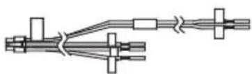
- 6 Pin Power/Dome Light Harness (P/N 112-4270) - (1 pc)
- AUX Pigtail (P/N 112-3227) - (1 pc)
- 5 Pin AV input Harness (P/N 112-4259) - (1 pc)
- 5 Pin AV output Harness (P/N 112-4260) - (1 pc)
- Trim Ring - Shale (P/N 306-250) - (1 pc)
- Pewter (P/N 306-251) - (1 pc)
- Black (P/N 306-252) - (1 pc)
- Snap On Cover (Screen Back) - Shale (P/N 306-253) - (1 pc)
- Pewter (P/N 306-254) - (1 pc)
- Black (P/N 306-255) - (1 pc)
- Snap On Cover (Shroud) - Shale (P/N 306-411) - (1 pc)
- Pewter (P/N 306-412) - (1 pc)
- Black (P/N 306-413) - (1 pc)
- Installation Guide & Owner's Manual (Not Shown) - (1 of each)
Optional Accessories : 1. Wireless Headphones w/ Batteries
Installing the Unit In A Vehicle
Tools Required
-
2 Phillips Screwdriver
-
1 Phillips Screwdriver
- Utility or Razor Knife
- Wire Strippers
- Upholstery hook tool (for removal of panels as necessary)
- Electrical Tape
- Masking Tape
- Marker pen – to mark headliner, to mark trim ring if used
-
Scribe (to mark trim ring if used)
-
Multimeter to verify 12 volt DC and continuity (Do not use a test light or logic probe)
-
Miscellaneous:
-
Electrical Connectors (to connect to vehicle power source, requirements will vary from vehicle to vehicle)
- DVD Disc, USB Content and HDMI device (to verify system operation after installation)
Preparation
Place the unit on a soft surface to avoid damaging the plastic.
Installing the Snap On Covers
The Unit is supplied with black, shale and pewter plastics to allow for a custom installation. Choose the desired color and install as follows.
1. Housing Housing | 2.~ Snap On Cover (Shroud)1 Pewter, 1 Shale, 1 Black Snap On Cover (Shroud)1 Pewter, 1 Shale, 1 Black | 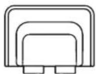 Snap On Cover(Screen Back Cabinet)1 Pewter, 1 Shale, 1 Black Snap On Cover(Screen Back Cabinet)1 Pewter, 1 Shale, 1 Black | 4.[7DS4]Slide Knob |
5.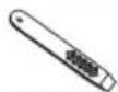 Pry Tool Pry Tool |
Installing the snap-on shroud
Installing the Shroud
*NOTE: Work on a soft surface to avoid damaging the plastic.
-
Remove the double sided tape backing from the two strips on the center section of the shroud.
-
Hook the shroud over the dome light and align the shroud tabs (1) with the eight openings around the rim of system (2).
-
Slide the shroud down until the shroud completely covers the system and that all eight tabs snap into all eight openings around the system (1) & , (2).
-
Apply pressure to the center section of the shroud in the area of the double sided tape to ensure that the tape adheres.
-
Locate the Slide Knob (3) in the hardware package and press it onto the dome light switch (4) on the side of the system.

Installing the Snap-On Screen Cover
Installing the Screen Cover
-
Open the LCD screen.
-
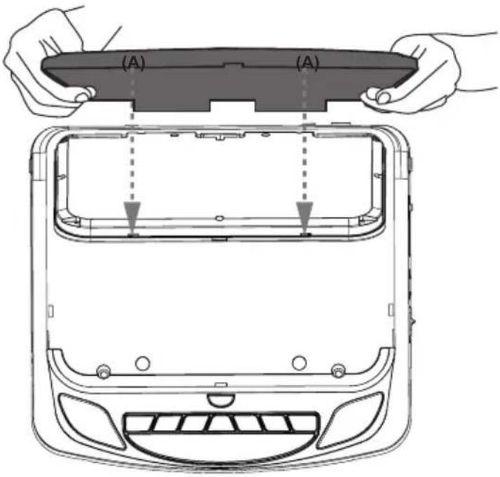
Hook the two tabs "A" (as shown) on the bottom edge of the screen.
-
Carefully snap the opposite side over the hinge.
NOTE: If the wrong color Shroud and Screen Cover is installed, refer to Appendix A of this manual for instructions to change the Shroud and Screen Cover color.
Installing the Trim Ring
The trim ring is attached to the video monitor using the perimeter screw bosses. It is important that the screws used in this installation are not over tightened, and that the video monitor and trim ring are mounted in such a way that the assembly does not distort (or bend) when the mounting screws are tightened.
There are two Trim Ring options for mounting the Unit, one is to use the supplied Trim Ring for all vehicles with flat headliner mounting areas (no contour) or a thick Trim Ring (not supplied) that can be cut to fit the contour of a headliner that is not flat (see Appendix B of this manual).
NOTE: The trim rings supplied with this unit are not designed to be trimmed.
Installing the Trim Ring
- Turn the system over on a surface with protective covering to prevent scratches.
- Place the trim ring onto the system. Align the pins on the trim ring with the holes in the metal chassis plate.

flowchart
graph LR
    A["Trim Ring"] --> B["System"]
    B --> C["Trim Ring on System"]
- Locate the eight (8) M3 x 5mm screws in the hardware kit.
- Using a screwdriver, install the eight (8) M3 x 5mm screws into the locations marked "A" shown in the figure below.
NOTE: Use caution tightening screws as the threads may strip in the overhead assembly.
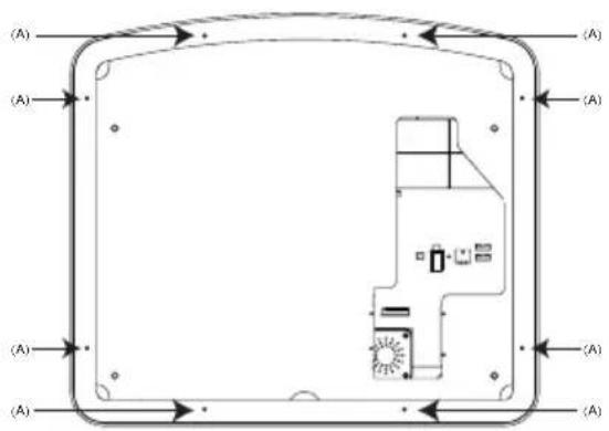
TRIM RING SCREW
(A) M3 X 5mm Screw (QTY 8)

General Vehicle Installation Approach
- Decide upon system configuration and peripheral options that will be installed (ie...External Video Gaming System).
- Review all manuals to become familiar with electrical requirements and connections.
- Decide upon mounting locations of all components and method of mounting.
- Prep the vehicle by removing any interior trim necessary to gain access to vehicle's wiring as well as all areas where interconnecting wire harnesses will need to be located. If any access holes need to be cut into the vehicle (headliner, other trim components etc.), this should be done now as well.
- Route the wiring harnesses throughout the vehicle as necessary including the wiring for any additional peripheral devices being added to this system. (as well as the wiring instructions for the individual components and accessory options being installed). Be sure that all wiring is protected from sharp edges and is routed in such a manner that wiring is not pinched when all components and interior trim are fully installed. Be sure to leave enough slack in the wiring at each component to allow working room. Avoid routing wiring near or over airbag wiring or airbags.
- Remove all A/V system components from their packaging and place them loosely in the vehicle at their respective locations.
- Connect all components together (electrically) and verify proper operation of all system functions.
Note: Testing of the system is best performed BEFORE the Overhead Monitor is mounted to the supplied bracket and any optional accessories are permanently mounted. - After verifying proper operation of the system proceed to mount each component.
- When all components are mounted recheck the function of the entire system again to ensure that no wiring was pinched or connected improperly during final installation.
Vehicle Preparation
- Locate an accessory +12v power source with a good ground. These wires can be found at the ignition switch or fuse-box.
Power Source
- +12v when the key is in the ACC and run positions.
- 0v when the key is OFF.
NOTE: Always fuse the ACC +12V at the source where it is connected to the vehicle.
- Some vehicles come equipped with a factory fuel saver mode that places the vehicle in an "Environmental Friendly" mode that shuts down the engine when the vehicle is not in motion. This system is equipped with a built-in voltage stabilizer to provide the necessary voltage to the system when a "Stop/Start" fuel saver mode in engaged. In some instances (vehicle dependent on how low the voltage drops when engaged), an additional voltage stabilizer may be required to overcome this vehicle feature and maintain the needed voltage to maintain system operation.
- The mounting method and location will vary from vehicle to vehicle, the only focus of this manual is to provide proper installation guidance for this system.
- Generally, the best location for the video monitor is where the vehicle's factory dome light is installed. The monitor should be located in such a manner that it can be comfortably viewed by rear seat passengers.
NOTE: Never install the monitor in a place within the driver's view. This is not only dangerous, but it is also illegal in many states.
- Once the mounting location of the monitor has been determined, additional preparation work may be necessary, depending on the vehicle structure and installation method. Some of the steps that may be required are:
a. Removal of the vehicle's dome light.
b. Cutting an opening in the headliner to install the mounting bracket.
c. If the optional Thick Trim Ring will be used, it may have to be trimmed to fit the contour of the vehicle's headliner. Refer to Appendix B Installing the Optional Thick Trim Ring.
Connecting the Dome Lights
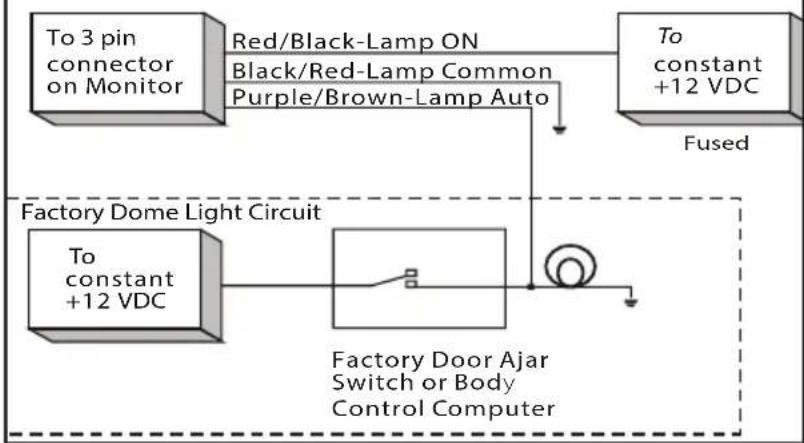
The dome lights in the video monitor require three connections to the vehicle's wiring. There are two common types of dome light circuits used, positive switched systems or negative switched systems. Positive switched systems supply voltage to the interior lights to turn ON; negative switched systems apply ground to illuminate the bulbs.
To determine which system you have to locate the wires at the dome light:
- On a positive switched system, with all the doors closed and the lights out, both wires at the dome light will rest at ground. When the light is activated, one of these wires will switch to +12 VDC. This is the vehicle's switching wire Lamp auto.
- On a negative switched system, with all the doors closed and the lights out, both wires at the dome light will rest at +12 VDC. When the light is activated, one of these wires will switch to ground. This is the vehicle's switching wire Lamp auto.
For positive switched systems, connect the Purple / Brown (Lamp Auto) wire to the vehicle's switched wire. Then connect the Red / Black (Lamp ON) wire to a fused constant 12 volt source and the Black / Red (Lamp Common) wire to a good ground. Positive switched systems are commonly found on Ford vehicles.
For negative switched systems, connect the Purple / Brown (Lamp Auto) wire to the vehicle's switched wire. Then connect the Red / Black (Lamp On) wire to a good ground and the Black / Red (Lamp Common) wire to a fused constant 12 volt source. Negative switched systems are commonly found on General Motors and import vehicles.
NOTE: Some vehicles which incorporate transistorized control of the dome light circuit, may require that the Purple / brown (Lamp Auto) wire be connected to the door pin switch wire, as the additional current draw of the monitor's lights may not be supported by the output of the vehicle's body control computer.
After wiring the dome lights make sure the dome lights operate properly with doors opening and closing and that they are not always on. Do not leave the dome lamp switch on the DVD overhead in ON position as this will drain the battery over time.
Positive Switched Dome Lighting
flowchart
graph TD
    A["To 3 pin connector on Monitor"] --> B["Red/Black-Lamp ON"]
    B --> C["Black/Red-Lamp Common"]
    B --> D["Purple/Brown-Lamp Auto"]
    E["To constant +12 VDC"] --> F["Fused"]
    G["Factory Dome Light Circuit"] --> H["To constant +12 VDC"]
    H --> I["Factory Door Ajar Switch or Body Control Computer"]
Negative Switched Dome Lighting

flowchart
graph TD
    A["Factory Door Ajar Switch or Body Control Computer"] --> B["Fused"]
    B --> C["To constant +12 VDC"]
    C --> D["Red/Black-Lamp on Black/Red-Lamp common Purple/Brown-Lamp Auto"]
    D --> E["To constant +12 VDC"]
    E --> F["Ground"]
    style A fill:#f9f,stroke:#333
    style B fill:#ccf,stroke:#333
    style C fill:#cfc,stroke:#333
    style D fill:#fcc,stroke:#333
    style E fill:#cff,stroke:#333
Installing the Mounting Bracket
Installing the Mounting Bracket
-
Once all the pre-wiring is complete, locate:
-
Mounting Bracket
• (4) #8 x 3/8" Self-Drilling Screws -
Carefully align the Mounting Bracket in the location it is to be installed with direction arrow facing the front of the vehicle (make sure there is nothing between the Mounting Bracket and Roof Cross-Member).
NOTE: The headliner may need to be cut to install the bracket. When cutting the headliner, make sure no wires above the headliner are cut.
- While holding the Mounting Bracket in place, install the 4- #8 x 3/8" Self-Drilling Screws.
CAUTION: Be sure that the Self-Drilling Screws do not pierce the outer roof skin when fully fastened to the Roof Cross-Member.
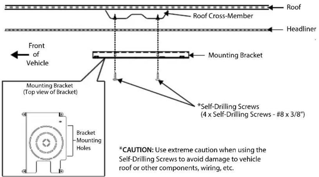
WARNING: Any use of a mounting substrate other than the supplied bracket may result in performance issues. The supplied bracket was designed to ensure this Mobile Video System is properly installed without adding any strain or stress to the system which could result in unit operation problems.
Installing the Unit Video System-Wiring Diagram
- Connect the 6 pin harness to the unit and make the connections to the vehicle.
- Connect the red and black power wires of the Power Harness to vehicle's electrical system by connecting into an accessory hot line and a good ground. Soldering all power connection is the suggested technique that should be used to ensure a problem free connection.
- If connecting to an external source, connect the 5 Pin AV Input Harness (112-4259 Blue Connector) to provide AV signal input to the system.
- If connecting to an external source, connect the if used 5 Pin AV Output Harness (112-4260 White Connector) to provide AV signal output from the system.
- Verify all system functions before final mounting of the finished assembly.
Input Source Options
- Internal User Accessible: DVD/USB/HDMI/AUX AV Inputs
- External Hidden: AV Input via supplied harness 112-4259 AV Output via supplied harness 112-4260
NOTE: The antenna has been designed for optimal performance. When installing the unit, position the antenna for best reception.
Installing the Unit Video System-Wiring Diagram
Wiring Diagram

Installing the Unit Video System-Mounting the Unit
Installing the System
-
Make all electrical connections.
-
Attach the Unit to the mounting bracket using four M5 screws.
CAUTION: The M5 screws are supplied in three different lengths (10mm, 20mm and 40mm) to facilitate proper installation. Use extreme caution when using these screws to avoid damage to vehicle roof or other components, wiring, etc.
CAUTION: Do not trap any bulk wiring or other accessories such as filters between the supplied bracket and the unit. Any such items can block air flow in addition to placing pressure on the top of the unit which could lead to performance issues.
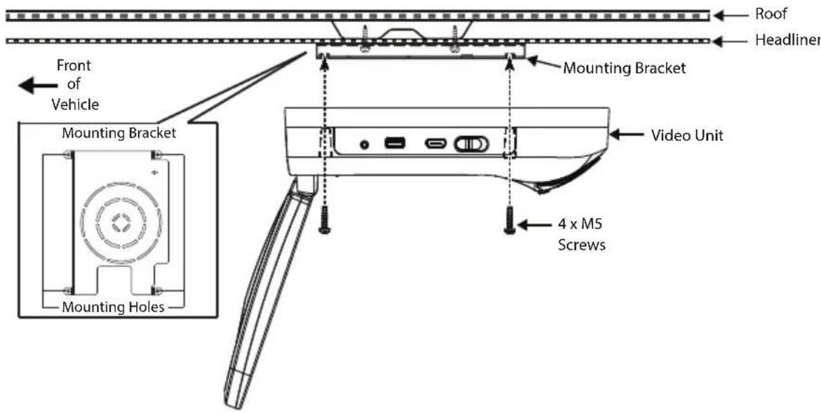
Appendix A - Removing the Screen Back Cover
This section is intended for situations where the color of the Shroud, Screen Cover and Trim Ring need to be changed after the unit is setup for installation.
NOTE: Work on a soft surface to avoid damaging the plastic.
Removing the Screen Back Cover
- Starting from the back of the unit, carefully insert the supplied pry tool between the Housing and Screen Back Cover.
- Press the pry tool to release the Screen Back Cover.
- While lifting the Screen Back Cover, slide the pry tool around to the attaching areas and press the pry tool to release the Screen Back Cover.
- Remove the Screen Back Cover and discard.

Appendix A - Removing the Trim Ring and Shroud
Removing the Trim Ring
- Remove the Trim Ring screws ((8) M3 x 5mm screws).
NOTE: Do not Discard Screws! These screws are used to attach the new Trim Ring.
- Remove the Trim Ring and discard.

TRIM RING SCREW
(8) M3 X 5mm Screws
Removing the Shroud
- Using the supplied pry tool, remove the slide knob from the dome light switch located on the side of the system.
NOTE: Do not Discard knob! The knob is reused.
- Open the screen and insert the supplied pry tool between the Housing and Shroud and disengage the tape on the center section of the shroud.
- Press the pry tool to disengage the attaching Shroud clips.
- Continue disengaging the attaching areas around the unit removing the Shroud and discard.

natural_image
Three-step illustration showing a hand holding a device, with arrows indicating sequence (no text or symbols)Appendix B - Installing the Optional Thick Trim Ring
This section covers only special installation considerations for the optional thick trim ring installation. Consideration for when an installation requires use of our Optional thick trim ring.
Important NOTES before installing the thick trim ring:
- There should be a gap between the headliner and the outer flange of the video monitor.
- Apply masking tape to the outside of the thick trim ring.
- Mark the cut line to follow the necessary contour of the roof. The suggested method of marking is as follows:
a. First mark the narrowest point of the trim ring on the masking tape. Be careful to consider not only vertical location, but fore-aft location.
b. Using the handle of a screwdriver, make a "transfer marking tool". See diagram below. Place the tool against the roof and the marker against the masking tape on the trim ring. Trace the cut to be made around the entire perimeter of the trim ring.
-
Cut the trim ring using a sharp utility knife or shears. Make the cut in several passes over the marked line, each time cutting a little deeper. It is not necessary to cut completely through the plastic, the cut only need be over 50% of the wall thickness of the plastic. By bending the cut back and forth several times, the plastic will break cleanly at the cut.
-
Check the fit of the trimmed console and make any minor adjustments necessary.

THICK TRIM RING PART NUMBERS
Shale - 1187270PL
Pewter- 1187271PL
Black-1187272PL
Tape marker to screwdriver handle. Starting at your mark for the lowest point, trace the contour of the roof around the perimeter of the trim ring.
Troubleshooting
| SYMPTOM: | REMEDY: |
| No power at video monitor | Verify +12 VDC on the Red wire at 6 Pin Power/Dome Light Harness behind the video monitor.Verify a ground connection with a continuity test from a known good ground to the black wire. |
| Power but no video or sound | Verify that the Source is on and playing back compatible media content. |
| Disc will not play or wrong region is displayed | Check to ensure the disc was put in with the correct side for playback (Label side up/shiny side down).NOTE:The DVD system only plays digital video discs, audio CDs and MP3s.Both the unit and the disc are coded by region. If the regional codes don’t match, the disc can’t be played. This DVD player is set to Region 1. |
| IR Wireless Headphones do not work | Check if batteries are installed correctly.Make sure that the headphone batteries are fresh.Check if Power Button lights up when pressed.If Power Button does not light up when pressed, change batteries.If using Dual Channel Wireless Headphones, make sure the correct channel is selected.Make sure the IRT power is ON. Press the IRT ON/OFF button on the remote control and IRT ON or IRT OFF is displayed. |
Troubleshooting
| SYMPTOM:FM Transmitter does not work | REMEDY:Check if radio is ON and in FM mode.Check that radio is tuned to the same frequency as the unit is set to.Select another FM channel.Reposition the Unit Wireless FM antenna for better reception.OptionalModuleFMDIRBwillallowtheinternal FM Transmitter to become a hardwired FM modulator. This option will provide the best FM connection to the vehicle radio. |
| Remote Control does not work | Check if the battery is installed correctly.Make sure that the remote control battery is fresh.The remote control is a dual function remote control, make sure M1/M2 is selected correctly. |
| HDMI source does not work with smartphone | A special adapter is required to connect a smartphone to the HDMI input. Contact the smartphone service provider for ordering information on the appropriate adapter. |

For Customer Service
Visit Our Website At
www.voxxelectronics.com
Product Information, Photos,
FAQ's, Owner's Manuals
AMVXMTG13/VXMTG13
13.3" Overhead LCD Monitor With Built-In DVD Player Owner's Manual


- Warnings
- Safety Precaution
- Table Of Contents
- Materials Included In This Package
- x 3/8" Self Drilling Screws - (4 pcs)
- Installing the Unit In A Vehicle
- Tools Required
- Phillips Screwdriver
- Phillips Screwdriver
- Preparation
- Installing the Snap On Covers
- Installing the snap-on shroud
- Installing the Shroud
- Installing the Snap-On Screen Cover
- Installing the Screen Cover
- Installing the Trim Ring
- General Vehicle Installation Approach
- Vehicle Preparation
- Power Source
- Connecting the Dome Lights
- Installing the Mounting Bracket
- Installing the Unit Video System-Wiring Diagram
- Installing the Unit Video System-Mounting the Unit
- Installing the System
- Appendix A - Removing the Screen Back Cover
- Removing the Screen Back Cover
- Appendix A - Removing the Trim Ring and Shroud
- Removing the Trim Ring
- Removing the Shroud
- Appendix B - Installing the Optional Thick Trim Ring
- Troubleshooting
- AMVXMTG13/VXMTG13
Brand : AUDIOVOX
Model : Voxx VXMTG13
Category : Dashboard camera