
XBS-5000-R - Automatic barrier AccessPRO - Free user manual and instructions
Find the device manual for free XBS-5000-R AccessPRO in PDF.


| Product Type | Electronic Device (Uncategorized) |
| Brand | AccessPRO |
| Model | XBS-5000-R |
| Dimensions (approx.) | 12 x 8 x 2.5 inches (30 x 20 x 6 cm) |
| Weight (approx.) | 3.3 lb (1.5 kg) |
| Power Supply | AC 100-240V, 50/60 Hz, 0.5A |
| Power Consumption | 15W (typical) |
| Main Functions | Operation, programming, connectivity, display |
| User Interface | Buttons, LED indicators, LCD screen |
| Cleaning Instructions | Wipe with a soft, dry cloth; avoid liquids |
| Maintenance | Keep firmware updated; store in dry place |
| Safety Warnings | Do not expose to moisture; use only supplied adapter |
| Spare Parts Availability | Contact manufacturer or authorized dealers |
| Repairability | Service by qualified personnel only |
| Operating Temperature | 32°F to 104°F (0°C to 40°C) |
| Storage Temperature | -4°F to 140°F (-20°C to 60°C) |
| Warranty | 1 year limited warranty |
Frequently Asked Questions - XBS-5000-R AccessPRO
User questions about XBS-5000-R AccessPRO
0 question about this device. Answer the ones you know or ask your own.
Ask a new question about this device
Download the instructions for your Automatic barrier in PDF format for free! Find your manual XBS-5000-R - AccessPRO and take your electronic device back in hand. On this page are published all the documents necessary for the use of your device. XBS-5000-R by AccessPRO.
USER MANUAL XBS-5000-R AccessPRO
Automatic barrier operation manual

natural_image
Silhouette of a barrier with a diagonal stripe and serrated base (no text or symbols)XBSBOARD
Please read this manual carefully before installation and operation
INDUSTRIAL
by AccessPRO
Warning
- Before installing and operating the automatic barrier please read this manual.
- Do not install this product on areas with vibration, high temperature, high humidity, flammable areas, explosives, with dust or corrosive gas.
- Because there is electricity with high voltage inside the product, non trained staff shouldn't open the product, this is to avoid an electric shock. We recommend hiring a professional to perform the installation
- The manufacturer will not assume responsibility on damage caused by unauthorized changes on the original design of the barrier.
- An "air-break" switch must be connected with the connector on the power supply input.
- Before powering and turning the controller manually adjust the barrier on its middle position (45°).
- Disconnect the power supply before manually operating the barrier.
- Make sure the path is not obstructed when the barrier is operating.
- Security devices such as photocells and air break switches are highly recommended. Check and test them periodically to ensure proper operation
- Properly handle accessories including plastic bag and screws to avoid hazards such as accidents and suffocation.
- Save this manual for future reference.
Description
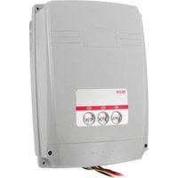
Panel Description

INDUSTRIAL
by AccessPRO
Input Voltage
| Input voltage | AC 130 V 50 / 60 Hz |
| Consumption on “stand-by” | < 2 W |
| Power | 750 W |
| Operating temperature | -20 °C ~ 50 °C |
| Storage temperature | -30 °C ~ 70 °C |
| Relative Humidity | < 90% |

Open/Increase Value Stop/OK/Save


Close/Decrease Value
Main Features
2.1 Digital positioning, high precision and simple configuration.
2.2 Auto diagnostic and smart auto protection.
2.3 Timed automatic closing function.
2.4 Safety/protection function performed by external sensors.
2.5 Remote control.
2.6 Counting mode.
INDUSTRIAL
by AccessPRO
Main Features
2.1 Digital positioning, high precision and simple configuration.
2.2 Auto diagnostic and smart auto protection.
2.3 Timed automatic closing function.
2.4 Safety/protection function performed by external sensors.
2.5 Remote control.
2.6 Counting mode.
INDUSTRIAL
by AccessPRO
Electrical Connections

INDUSTRIAL
by AccessPRO
Aperture adjustment limits
Limit aperture, limit closing, the controller initially installed will operate normally through the following configuration steps
Note: For the initially installed controller, manually adjust the barrier on a medium position or 45^ before turning it on.
Configuration Steps

flowchart
graph TD
    A["Turn barrier ON"] --> B["Press and hold the "R" button for more than 3 seconds, then press the remote control button till "P-1" caption appears on the display"]
    B --> C["Press the "Y" button twice and observe the barrier."]
    C --> D{Is the barrier opening?}
    D -->|No| E["Turn the barrier OFF"]
    E --> F["Invert the motor cables L1 & L2"]
    F --> G["Turn barrier ON"]
    G --> H["Press and hold the "Y" button till the barrier is vertical"]
    H --> I["Press the "R" button once and "P-2" will be shown"]
    I --> J["Press the "B" button once"]
    J --> K["Press and hold the "B" button till the barrier is horizontal"]
    K --> L["Press the "R" button 5 times"]
    L --> M["End"]
INDUSTRIAL
by AccessPRO
Adjust precise limits
Note:
If you expect the barrier to stop after the original established position, please press the "Y" button. If you expect the barrier to stop before the original established position, please press the "B" button.
Configuration steps
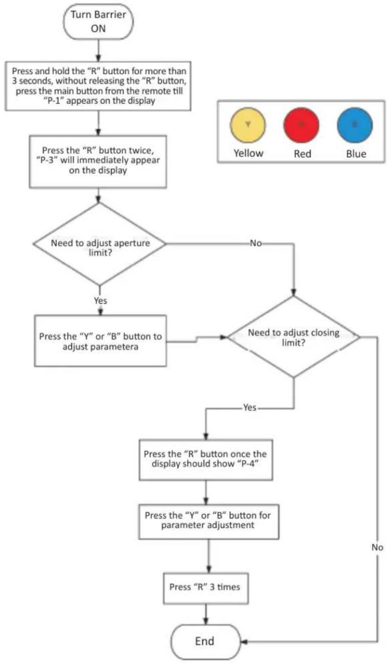
flowchart
graph TD
    A["Turn Barrier ON"] --> B["Press and hold the "R" button for more than 3 seconds, without releasing the "R" button, press the main button from the remote till "P-1" appears on the display"]
    B --> C["Press the "R" button twice, "P-3" will immediately appear on the display"]
    C --> D{Need to adjust aperture limit?}
    D -->|No| E{Need to adjust closing limit?}
    D -->|Yes| F["Press the "Y" or "B" button to adjust parametera"]
    E --> G{Need to adjust closing limit?}
    G -->|Yes| H["Press the "R" button once the display should show "P-4""]
    G -->|No| I["End"]
    H --> J["Press the "Y" or "B" button for parameter adjustment"]
    J --> K["Press "R" 3 times"]
    K --> L["End"]
INDUSTRIAL
by AccessPRO
Automatic closing configuration with delay
Function description: The barrier will automatically close after an established time starting when the barrier is completely open.
Note1: The factory setting is "0" meaning that the functions is disabled.
Note2: The maximum delay values is 99 seconds.
Configuration steps
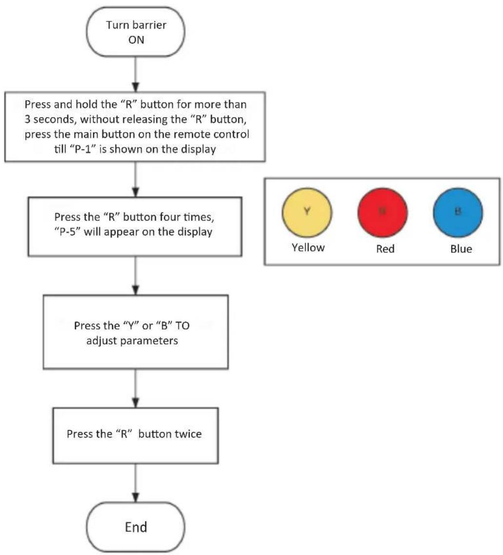
flowchart
graph TD
    A["Turn barrier ON"] --> B["Press and hold the "R" button for more than 3 seconds, without releasing the "R" button, press the main button on the remote control till "P-1" is shown on the display"]
    B --> C["Press the "R" button four times, "P-5" will appear on the display"]
    C --> D["Press the "Y" or "B" TO adjust parameters"]
    D --> E["Press the "R" button twice"]
    E --> F["End"]
INDUSTRIAL
by AccessPRO
Counting configuration mode
Function description: If there is several simple entries, the barrier will automatically close once the vehicles cross the magnetic loop.
Configuration steps

flowchart
graph TD
    A["Turn barrier ON"] --> B["Press and hold the "R" button for more than 3 seconds, without releasing the "R" button, press the main button on the remote control till "P-1" is shown on the display"]
    B --> C["Press the "R" button five time, "P-6" will appear on the display"]
    C --> D["Press the "Y" button once"]
    D --> E{Do you wish to activate counting mode?}
    E -->|No| F["Press the "B" button once"]
    E -->|Yes| G{Does ON appear on the display?}
    G -->|No| H["Press the "Y" button once"]
    G -->|Yes| I["Press "R" button once"]
    F --> J["End"]
    H --> J
INDUSTRIAL
by AccessPRO
Additional Functions - dip switch configuration
| Lamp operation mode | Lamp output works works like a signaling lamp |  | ON1 2 3 | Lamp output in traffic light mode |
 | ||||
| Work mode configuration of security device input | Supports protection devices like photo-cells and mass sensors the feature a COM / NC relay output |  | Acepta dispositivos como fotoceldas y sensores de masa que cuentan con salidas de relevador COM/NO |  |
 |  | |||
| Display work mode Shows barrier operation status | 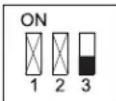 | Shows the encoders actual value. |  | |
 |  | |||
INDUSTRIAL
by AccessPRO
Error code table
| Code | Meaning | Solution |
| Err1 Invalid encoder signal Check signalling | ing cables and connectors. | |
| Err2 Time finished on the barriers operation | Check the mechanical system. | |
| Err3 Motor rotor locked 1. Check the mechanism system. | 2. Check the motor connection cables. | |
| Err7 Photocell triggers Remove the object that blocks the photocell. | photocell. | |
| Err8 Remove the object that blocks the airflow switch triggers | airflow switch. | |
| ErrA Invalid parameter limits | Establish parameter “P-1” & “P-2” again, referred on page 6. | |
- Automatic barrier operation manual
- INDUSTRIAL
- by AccessPRO
- Warning
- Description
- Panel Description
- Main Features
- Aperture adjustment limits
- Adjust precise limits
- Note:
- Automatic closing configuration with delay
- Counting configuration mode
- Additional Functions - dip switch configuration
- Error code table
Brand : AccessPRO
Model : XBS-5000-R
Category : Automatic barrier