XBA-DROPARM - Automatic barrier AccessPRO - Free user manual and instructions
Find the device manual for free XBA-DROPARM AccessPRO in PDF.


| Brand | AccessPRO |
| Model | XBA-DROPARM |
| Product Type | Monitor Arm / Desk Mount |
| Material | Aluminum alloy and steel |
| Weight Capacity | Up to 22 lbs (10 kg) |
| VESA Compatibility | 75x75mm and 100x100mm |
| Mounting Options | Clamp (desk thickness up to 3.3") and grommet mount |
| Height Adjustment Range | 0-18 inches (0-457mm) |
| Arm Reach | Up to 24 inches (610mm) |
| Tilt Range | -90° to +90° |
| Swivel Range | 360° |
| Rotation (Landscape/Portrait) | 180° |
| Cable Management | Integrated cable clips and channels |
| Dimensions (Arm) | 5.5" x 3.5" x 24" (140 x 89 x 610 mm) |
| Net Weight | 6.5 lbs (2.95 kg) |
| Color | Matte black |
| Power Source | None (manual operation) |
| Gas Spring Assistance | Yes, for smooth height adjustment |
| Included Accessories | Clamp, grommet bracket, mounting hardware, cable ties |
| Cleaning Instructions | Wipe with a dry cloth; avoid harsh chemicals |
| Safety Certification | Desk mount tested for stability |
| Warranty | 2 years limited |
| Spare Parts Availability | Contact AccessPRO customer service |
Frequently Asked Questions - XBA-DROPARM AccessPRO
User questions about XBA-DROPARM AccessPRO
0 question about this device. Answer the ones you know or ask your own.
Ask a new question about this device
Download the instructions for your Automatic barrier in PDF format for free! Find your manual XBA-DROPARM - AccessPRO and take your electronic device back in hand. On this page are published all the documents necessary for the use of your device. XBA-DROPARM by AccessPRO.
USER MANUAL XBA-DROPARM AccessPRO
Flying Boom Holder's User Manual
Installation Guide
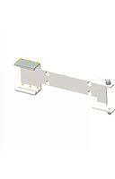
- Using 4 PCS M10X20 bolts and 4 pcs M10 covers to fix the bellowed boom holder on the barrier, see pic. 1.

natural_image
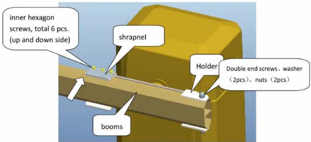
3D rendering of a yellow mechanical component with two white mounting brackets and a central rectangular block (no text or symbols visible)- Before installing the boom, pls unscrew those 6 pcs inner hexagon screws. (see pic2)
Pic. 2
- As per aboved Pic 2, place the booms onto the holder. (make sure all holes to match with each other)
- Install double-end screws, washers and nuts.
5.
INDUSTRIAL
by AccessPRO
- Fasten inner hexagon screws (up and down each 3 pcs). Check bellowed PIC 3 to install the boom and shrapnel to make sure the boom is attaching closely to back side of holder and boom will not shake when working.

natural_image
3D technical illustration of a structural component with yellow components and a gray top plate (no text or symbols)Working illustration
- Bellowed Pic 4 is the normal working situation for the barriers.

natural_image
3D diagram of a mechanical lever with a yellow component and an arrow indicating downward motion (no text or symbols)INDUSTRIAL
by AccessPRO
- When Cars or Vehicles will hit the booms towards the arrow showed direction, the boom will fly away the boom holder, but, still on boom holders. The booms will not be broken.

natural_image
3D diagram of a lever mechanism with a yellow block and white rail, showing an upward arrow (no text or symbols)- After Car pass by or leave, push the booms back to the former position and it will work normally again.
Attention
When booms have not been pushing back to the former correct position.
Please don't open or close the barriers!

Brand : AccessPRO
Model : XBA-DROPARM
Category : Automatic barrier