ECHO-ST - Access Point SilverNet - Free user manual and instructions
Find the device manual for free ECHO-ST SilverNet in PDF.


| Product Type | Wireless Access Point |
| Brand | SilverNet |
| Model | ECHO-ST |
| Dimensions | 180 x 120 x 30 mm |
| Weight | 300 g |
| Power Supply | PoE (802.3af) or DC 12V/1A |
| Wireless Standards | IEEE 802.11ac, dual-band (2.4 GHz & 5 GHz) |
| Maximum Data Rate | 1200 Mbps (300 + 867) |
| Ethernet Ports | 2 x Gigabit Ethernet (1 PoE input, 1 LAN) |
| Security | WPA2, WPA3, WEP, MAC filtering |
| Antennas | Internal dual-band antennas |
| Management | Web interface, mobile app (iOS/Android) |
| Mounting | Wall or ceiling mountable |
| Operating Temperature | 0°C to 40°C |
| LED Indicators | Power, LAN, WLAN, status |
| Firmware Upgrade | Via web interface |
| Maintenance | Clean with dry cloth; avoid liquids |
| Safety | Keep away from water and heat sources |
| Spare Parts | Not applicable (no user-serviceable parts) |
Frequently Asked Questions - ECHO-ST SilverNet
User questions about ECHO-ST SilverNet
0 question about this device. Answer the ones you know or ask your own.
Ask a new question about this device
Download the instructions for your Access Point in PDF format for free! Find your manual ECHO-ST - SilverNet and take your electronic device back in hand. On this page are published all the documents necessary for the use of your device. ECHO-ST by SilverNet.
USER MANUAL ECHO-ST SilverNet
natural_image
Three white industrial air purifiers with visible brand logos and control panel (no readable text or symbols on main body)SIL ECHO BS/ST
User Manual
Version 1.0 (27/06/2017)
Radio frequency Interference Requirements
The operation of this device in the 5.15 GHz to 5.25 GHz frequency range is restricted to indoor use. FCC regulations require this product to be used indoors while operating at 5.15 GHz to 5.25 GHz to reduce the potential for harmful interference. However, the operation of this device in the 5.25 GHz to 5.35 GHz frequency range is allowed for both indoor and outdoor use. High power radars are allocated as primary users of the 5.25 GHz to 5.35 GHz and 5.65 GHz to 5.85 GHz bands. These radar stations can cause interference with and/or damage to this device.
FCC Warning
This equipment has been tested and found to comply with the limits for a Class B digital device, pursuant to Part 15 of the FCC Rules. These limits are designed to provide reasonable protection against harmful interference in a residential installation. This equipment generates, uses, and can radiate radio frequency energy and, if not installed and used in accordance with the instructions, may cause harmful interference to radio communications. No guarantee exists that interference will not occur in a particular installation. If this equipment does cause harmful interference to radio or television reception (determined by turning the equipment off and on), the user is encouraged to try to correct the interference by one or more of the following measures:
- Reorient or relocate the radio/TV receiving antenna.
- Increase the separation between the equipment and the radio/TV receiver.
- Connect the equipment into an outlet on a circuit different from that to which the radio/TV receiver is connected.
- Consult the dealer or an experienced radio/TV technician for help. Modifications made to the product, unless expressly approved by SilverNet Limited, could void the user's authority to operate the equipment.
RF Exposure Requirements
To ensure compliance with FCC RF exposure requirements, the antenna used for this device must be installed to provide a separation distance of at least 20 cm from all persons and must not be co-located or operating in conjunction with any other antenna or radio transmitter. Installers and end-users must follow the installation instructions provided in this user guide.
SILVERNET
CE Statement
The ECHO range is intended to be used by suitably trained individuals or organisations that are familiar with the requirements of the R&TTE directive. In particular the client must ensure that appropriate antennas and transmit power levels are selected to ensure that all power limits are met. Hereby, SilverNet Limited declares that this device is in compliance with the essential requirements and other relevant provisions of the R&TTE Directive 1999/5/EC. However, the use of the following warning symbol

Means that this equipment is subject to restrictions of use in certain countries and selection of the correct country of operation (country code) will ensure that the device operates only on the frequencies permissible within that country. It is also the operator's responsibility to ensure that appropriate licenses have been sought when operating on licensed frequencies, for example UK Band C, 5725-5850 MHz
Copyright Information
Copyright ©2020 all rights reserved. No part of this publication may be reproduced, adapted, stored in a retrieval system, translated into any language, or transmitted in any form or by any means without the written permission of the supplier.
SILVERNET
Contents
Radio frequency Interference Requirements ....2
FCC Warning....2
RF Exposure Requirements 2
CE Statement....3
Copyright Information....3
1. Installing the radio ....6
1.1 Instructions before installing....6
1.2 Installation....7
1.3 Powering up the Radio....10
1.4 Accessing the radio.... 11
2. Software Configuration 12
2.1 Main Page....12
2.1.1 Status-WIRELESS....13
2.1.2 Status-NETWORK....15
2.1.3 Status-SYSTEM....16
2.1.4 Monitor-Throughput 17
2.1.5 Monitor-Interfaces....17
2.1.6 Monitor-ARP List....18
2.1.7 Monitor-STA Stats....18
2.1.8 Monitor-AP Stats....20
2.2 Radio Page 22
2.2.1 Basic Wireless Settings 22
2.2.2 Advanced Wireless Settings 25
2.2.3 WMM Settings 26
2.3 WIRELESS Page....27
2.3.1 AP/AP WDS Mode 27
2.3.2 Station/Station WDS Mode 29
SILVERNET
2.4 NETWORK....30
2.4.1 Bridge Mode 30
2.4.2 WISP/SOHO Router Mode 33
2.5 SERVICES....36
2.5.1 Web Server 36
2.5.2 NTP Client....37
2.5.3 Dynamic DNS....37
2.5.4 Wireless Client Rate Limit 37
2.5.5 MAC Control....39
2.6 SYSTEM 40
2.6.1 Device....40
2.6.2 Ping Watchdog 41
2.6.3 System Accounts....41
2.6.4 Configuration Management 42
2.6.5 Firmware upgrade 43
2.7 Tools....44
2.7.1 Ping 44
2.7.2 Traceroute 44
2.7.3 Site survey....45
2.7.4 Speed Test 45
Contact Us 46
Online Resources....46
SILVERNET
1. Installing the radio
1.1 Instructions before installing
You will need clear Line-Of-Sight for the units to work correctly. Locate a suitable mounting location with a pole between 30 and 60mm. Do not install anywhere that is illegal and please ensure you obey the local regulatory rules.
You may need the following tools,

Screw Driver

Wire stripper
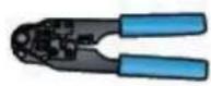
Cable clamp

Diagonal plier
SILVERNET
1.2 Installation
1
natural_image
Diagram showing a mechanical or electrical component with an orange curved arrow indicating motion (no text or symbols present)2
natural_image
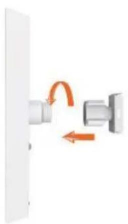
Close-up of a metallic mechanical joint or bracket assembly with a magnified inset showing a detail (no text or symbols visible)- Attach the Ball Joint Mount to the radio by rotating the lock nut clockwise by hand. Do not tighten the nut.
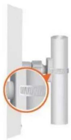
- Open the Metal strap and feed it through the two slots of the Ball Joint Mount, then wrap the Metal Strap around the pole.
3
natural_image
Diagram of a mechanical assembly with a magnified inset showing a component (no text or symbols)4
natural_image
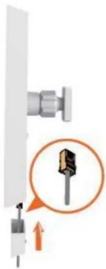
Close-up of a metallic cylindrical mechanical component with a flanged side (no visible text or symbols)- Pull out the port cover and connect an Ethernet cable to the port, then slide the cover back.
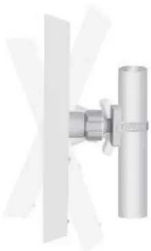
- Loosen the lock nut on the Ball Joint Mount and aim in the direction of the other end of the wireless link. Lock the nut.
SILVERNET
5
natural_image
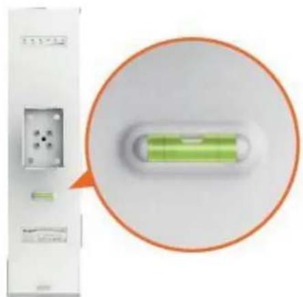
Close-up of a white electronic device with a green internal component and an orange circular annotation highlighting it (no visible text or symbols)- Make sure the air bubble stays in the middle of the level after installation
SILVERNET
natural_image
Illustration of a device with a handle and orange arrows indicating motion or force (no text or symbols)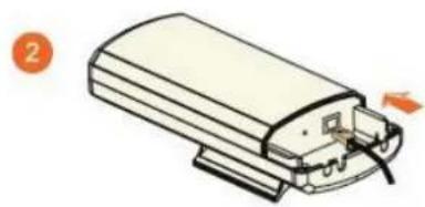
natural_image
Diagram of a device with a handle and internal components, no text or symbols present-
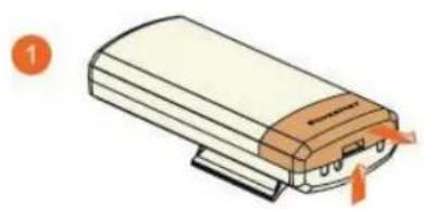
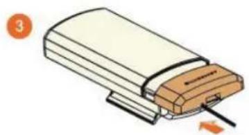
Press the buckle down and move the cover (highlighted) in the direction shown above.
-
Connect your Ethernet cable to the Ethernet port.
natural_image
Illustration of a device with a cable inserted into a housing (no text or symbols)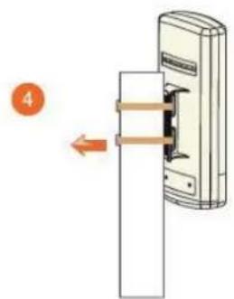
-
Replace the cover (highlighted) with the cable passing through the hole.
-
Mount the radio to a pole with the provided clip
NOTE
If you are using our 5GHz radios these should be connected with a Cat 5 or Cat 6 outdoor shielded grade Ethernet cable.
SILVERNET
1.3 Powering up the Radio
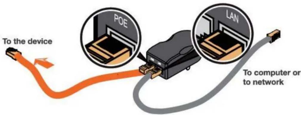
Connect the other end of the Ethernet cable to the PoE port of the provided PoE adapter. Then connect the LAN port of the PoE adapter to a PC or switch using a separate Ethernet cable. Finally, plug the PoE adapter into a standard electrical wall socket.
NOTE
If you use a PoE adapter which is not provided by SilverNet, we cannot provide warranty cover if the radio is damaged.
SILVERNET
1.4 Accessing the radio
- Configure the Ethernet adapter on your computer with a static IP address on the 192.168.1.x subnet (for example, IP address: 192.168.1.100 and subnet mask:
255.255.255.0
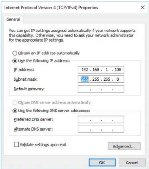
- Launch your web browser and enter the default IP address of your device (192.168.1.1) in the address field.

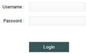
- Enter admin in the Username field and password in the Password field, and click Login.
SILVERNET
2. Software Configuration
2.1 Main Page
Status
![WIRELESS NETWORK SYSTEM Radio Wireless Mode : Access Point WDS Radio Mode : 11an Channel/Frequency : 140 / 5700 Tx Power : 23 dBm Channel Width : 20/40MHz Plus Tx Busy : 0 Region Code : United Kingdom Rx Busy : 0 Max Rate : 300 Mbps Total Busy : 0 TDMA : Disable Wireless1 [Up] SSID : SilverNet1 BSSID : 50:11:EB:10:08:30 Security : NONE Assoc Number : 0 Wireless2 [Down] Wireless3 [Down] Wireless4 [Down]](/content/2026/05/971422/images/5f276b64eab927283491bd7fd1a530cec0a5f23dfbfbd42ecbdf1b708ed6ef7b.jpg)
Figure 2-1 Wireless Status (Access Point WDS Mode)
Status
![WIRELESS NETWORK SYSTEM Radio Wireless Mode : Station WDS Radio Mode : 11an Channel/Frequency : 140 / 5700 Tx Power : 23 dBm Channel Width : 20/40MHz Plus Tx Busy : 0 Region Code : Compliance Test Rx Busy : 0 Max Rate : 300 Mbps Total Busy : 1 TDMA : Disable Station1 [Up] SSID : SilverNet1 BSSID : 50:11:EB:10:08:30 Security : NONE Signal Strength : -50 dBm](/content/2026/05/971422/images/19aaa5ed8fe2d813a66c64f05c4598c1e15148227066fdbe7f9fb61dac157af3.jpg)
Figure 2-2 Wireless Status (Station Mode)
2.1.1 Status-WIRELESS
The Radio status window displays a summary of the link status information
- Wireless mode: The mode the unit is currently set to, there are 4 modes the unit can run in. AP Mode, Station Mode, AP WDS Mode and Station WDS Mode.
- Radio mode: The working mode of the radio, which supports 802.11a/an which are two separate wireless transmission standards.
- Channel/Frequency: The radio's current working channel and working frequency.
- Channel Width: Displays the spectral width of the radio channel. A 40 MHz channel in a minimal interference environment will give up to twice the bandwidth of a 20 MHz channel.
- Country Code: set the country to which the unit is operating this will affect the channels you can use and the power of the radio in order to comply with the countries regulations.
- Tx Power: The transmission power of the radio. The higher your transmission power the more signal strength you will receive on a link.
Max Rate: The max transmission rate of the radio. Different channel bandwidth's have different max rates. A 40 MHz channel max rate is 300Mbps. The higher this rate on both ends of the link the better the transmission of the link. - TDMA: The status of TDMA - 'enabled' or 'disabled'.
Station status box shows the unit working in Station Mode.
| Station1 [Up] | |||
| SSID : | SilverNet1 | BSSID : | 50:11:EB:10:08:30 |
| Security : | NONE | Signal Strength : | -49 dBm |
Figure 2-3 Wireless Station Status
- Up/Down: UP means the Station has successfully connected with the AP. Down means there is no link.
- SSID: This is the name of the wireless network the AP is transmitting
SILVERNET
- BSSID: BSSID is the Mac address of the remote device. Use this to lock stations to AP's.
- Signal Strength: When there is a link between an AP and Station there will be a signal strength value. This is displayed as a negative so the smaller the value the better the signal strength.
■ Security: This is the level of security on the device
Wireless 1 (2, 3 and 4 only appear in the AP). The device can support up to 4 wireless services 1 to 4.
| Wireless1 [Up] | |||
| SSID : | Silvernetwireless | BSSID : | 50:11:EB:10:08:30 |
| Security : | WPA2AES | Assoc Number : | 0 |
| Wireless2 [Down] | |||
| Wireless3 [Down] | |||
| Wireless4 [Down] | |||
Figure 2-4 Wireless Access Point Status
- Up/Down: UP states the interface is enabled and providing wireless services. Down means it is disabled.
- SSID: This is the name of the wireless network the AP is transmitting
- BSSID: BSSID is the Mac address of the remote device. Use this to lock stations to AP's.
- Signal Strength: When there is a link between an AP and Station there will be a signal strength value. This is displayed as a negative so the smaller the value the better the signal strength.
■ Security: This is the level of security on the device - Assoc Number: current amount of stations connected to the AP.
2.1.2 Status-NETWORK
| WIRELESS | NETWORK | SYSTEM | ||
| Network Mode | ||||
| Mode : | Bridge | |||
| Management IP : | DHCP | |||
| LAN | ||||
| Bridge Name : | vbr1 | VLAN Description : | vlan1 | |
| IP Mode : | DHCP | IP Address : | 192.168.1.2 | |
| Port List : | eth0 ath0 | Bridge STP : | Disable | |
| Ethernet Interface | ||||
| eth0 : | 100Mbps/Full | |||
Figure 2-5 Network
Network Mode
- Mode: The device supports 3 different network modes Bridge Mode, SOHO Router Mode and WISP Mode.
A brief introduction to those modes:
- Bridge Mode: Bridge Mode is a 2-layer network mode. The unit ETH port and wireless interface are working at layer-2.
- SOHO Router Mode: This mode is typically a network router mode. The ETH port works as a WAN interface by connecting it to another network via an ETH port such as the Internet or personal network.
NOTE
The network mode can only be set as SOHO Router Mode when the unit is in AP Mode or AP WDS Mode.
- WISP Mode: This mode is opposite to the SOHO Router mode. It uses the wireless interface as a WAN to connect to a public network and the ETH port operates as a 2-layer access port.
NOTE
The network mode can only be set as WISP Mode when the unit is in Station Mode or Station WDS Mode.
LAN
SILVERNET
- Bridge Name: The name of the bridge interface
■ VLAN Description: The name of the VLAN interface
IP Mode : Will show as "static" or "DHCP" depending on the selected mode
IP address : The IP address of the device - Port List: The active ports on the device
- Bridge STP: Wil show as "Enabled" or "disabled"
2.1.3 Status-SYSTEM
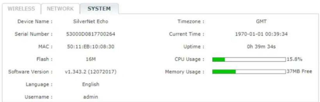
Figure 2-6 System label of status
■ Device Name: Device name or model name
- Serial Number: Device serial NO.
■ MAC: The MAC address of the device
- Flash: The flash memory of the device
■ Software Version: Current software version
- Language: Current web language
- Username: Username when login
■ Time zone: Current time zone
- Current time: Current time
- Uptime: How long the device has been on for
- CPU Usage: Shows the CPU usage as a percentage
■ Memory Usage: Shows the memory usage
2.1.4 Monitor-Throughput
Monitor
Throughput | Interfaces | ARP | STA Stats | Routes | Log
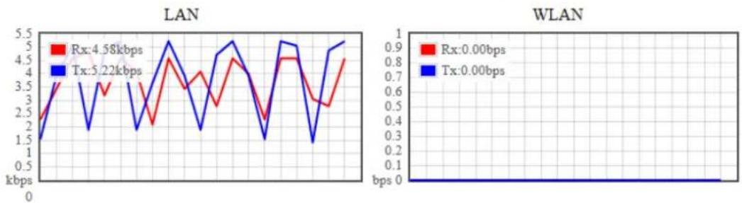
line
| Network | Rx (kbps) | Tx (kbps) | |---------|-----------|-----------| | LAN | 4.58 | 5.22 | | WLAN | 0.00 | 1.0 |Figure 2-7 Monitor-Throughput
2.1.5 Monitor-Interfaces
Interfaces list counts the send-receive information of all interfaces.
Monitor
Throughput | Interfaces | ARP | STA Stats | Routes | Log
| Interface | MAC | Tx Bytes | Tx Packets | Tx Error | Rx Bytes | Rx Packets | Rx Error |
| eth0 | 50:11:EB:10:08:30 | 2.08M | 8031 | 0 | 1.36M | 9602 | 0 |
| vbr1 | 50:11:EB:10:08:30 | 2.03M | 8032 | 0 | 1.17M | 9602 | 0 |
| ath0 | 50:11:EB:10:08:30 | 36.73K | 198 | 0 | 0.00K | 0 | 0 |
Figure 2-8 Monitor-Interfaces
- Interface : Listing all interfaces and interface names.
- MAC Address : Listing MAC address of all interfaces.
- Tx Bytes : Sending bytes number.
- Tx Packet : Sending packets.
- Tx Err : Sending error packet.
- Rx Bytes : Receiving bytes.
- Rx Packet: Receiving packet.
- Rx Err: Receiving error packet.
SILVERNET
2.1.6 Monitor-ARP List
ARP List counts the ARP information of device. As Figure 2-9.
Monitor
Throughput | Interfaces | ARP | STA Stats | Routes | Log
IP
192.168.1.143
MAC
E0:DB:55:AB:3D:B6
Interface
vbr1
Figure 2-9 Monitor-ARP List
- IP: IP address of device.
■ MAC: MAC address corresponding to IP address of device. - Interface: Interface of the IP address of device.
■ Type: Interface hardware type of learning ARP.
2.1.7 Monitor-STA Stats
When the unit is set to AP WDS Mode, the list shows STA info of current clients connected as Figure 2-10
Monitor
Throughput | Interfaces | ARP | STA Stats | Routes | Log
MAC
SSID Device Name Signal Type Distance IP Address Connect Time Action
50:11:EB:10:07:D8
SilverNet1 SilverNet Echo
44 11an 150m
192.168.1.1 00 - 01:03:08
kick
Figure 2-10 Monitor-STA Stats
SILVERNET
| MAC: | 50:11:EB:10:07:D8 | Connection Time: | 00 - 01:04:00 | ||
| AID: | 1 | Bandwidth: | 20/40MHz Plus | ||
| SSID: | SilverNet1 | PS Mode: | Active | ||
| Mode: | 11an | Auth Mode: | OPEN | ||
| RSSI: | 44 | Encryption: | NONE | ||
| VLAN: | 1 | Listen Interval: | 10 | ||
| Distance | 150m | ||||
| Tx/Rx Packets: | 13843/15614 | ||||
| Tx/Rx Bytes: | 2.53M/3.28M | ||||
| Tx/Rx Rate: | 300 Mbps/300.1 Mbps | ||||
| Tx/Rx Statistic: | |||||
| Rates: | Tx: | Rx: | |||
| 6.5 | 0 | 0 | |||
| 13.5 | 0 | 0 | |||
| 27 | 0 | 0 | |||
| 40.5 | 0 | 0 | |||
| 54 | 0 | 0 | |||
| 81 | 0 | 0 | |||
| 108 | 0 | 0 | |||
| 121.5 | 0 | 0 | |||
| 162 | 0 | 2 | |||
| 216 | 8 | 67 | |||
| 243 | 47 | 783 | |||
| 270 | 186 | 1018 | |||
| 300 | 13601 | 13708 | |||
| Add to Whitelist | Add to Blacklist | Kick | Refresh | Close | |
Figure 2-11 Station Details
- BSSID : BSSID of station.
- Mode: The mode of Station Radio.
AID: connecting ID of Station.
■ Signal: AP detected RSSI of the Station. - Assoc Time: Uptime of STA.
- Tx/Rx Packets: send-receive packets between AP and Station. Tx means sending packets, Rx means receiving packets.
- Tx/Rx Bytes: send-receive bytes between AP and STA. Tx means sending bytes, Rx means receiving bytes.
- Tx/Rx Rate: The rate the packets are sent-received between AP and Station.
2.1.8 Monitor-AP Stats
When the unit is in Station Mode, the list shows information of the connected AP, as Figure 2-12
Monitor
Throughput | Interfaces | ARP | AP Stats | Routes | Log
| SSID: | SilverNet1 | BSSID: | 50:11:EB:10:08:30 |
| Device Name: | SilverNet Echo | Distance: | 150m |
| Mode: | 11an | Channel: | 140 |
| RSSI: | 52 | Assoc Time: | 00 - 01:05:32 |
| Tx/Rx Packets: | 15941/15111 | Tx/Rx Bytes: | 3.33M/2.90M |
| Tx/Rx Rate: | 300 Mbps/300.1 Mbps | Security: | NONE |
Figure 2-12 Monitor-AP Stats
- SSID: SSID name of the AP that the Station is connecting to.
■ BSSID: BSSID address of the AP that the Station is connecting to.
■ Device Name: The name of the device
■ Distance: The estimated distance
■ Mode: The Radio work mode of the AP that the Station is connecting to.
- Channel: The channel of the AP that the Station is connecting to.
■ Signal: station detected AP RSSI.
- RSSI: The Receive signal strength
- Assoc Time: Up time after the station has connected to AP.
- Tx/Rx Packets: send-receive packets between AP and Station. Tx means sending packets, Rx means receiving packets.
- Tx/Rx Bytes: send-receive bytes between AP and STA. Tx means sending bytes, Rx means receiving bytes.
- Tx/Rx Rate: The rate the packets are sent-received between AP and Station.
■ Security: The security mode the device is using
2.1.9 Monitor-Routes
Routes list shows current routing relationship of devices, as Figure 2-13.
Monitor
Throughput | Interfaces | ARP | STA Stats | Routes | Log
| Destination | Netmask | Gateway | Interface |
| 192.168.1.0 | 255.255.255.0 | 0.0.0.0 | vbr1 |
Figure 2-13 Monitor-Routes
- Destination: Destination address
- Netmask: The subnet mask
- Gateway: The address of the router on the network if applicable.
- Interface: The interface relating to this routing info.
SILVERNET
2.2 Radio Page
The Radio Page is mainly used for setting up the wireless LAN parameters
Basic Settings
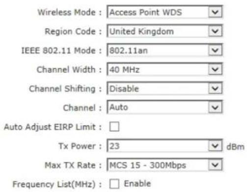
Figure 2-17 Radio Page
2.2.1 Basic Wireless Settings
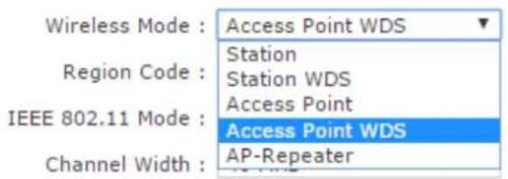
Figure 2-18 Wireless Mode
- Wireless Mode: The mode of the WLAN. There are 4 modes the unit can run in. AP Mode, Station Mode, AP WDS Mode and Station WDS Mode. The default is AP WDS Mode.
SILVERNET
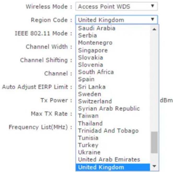
Figure 2-19 Country Code
■ Region code : The default set region code is United Kingdom.

Figure 2-20 IEEE 802.11 Mode
- IEEE 802.11 Mode: The default mode is 802.11an.
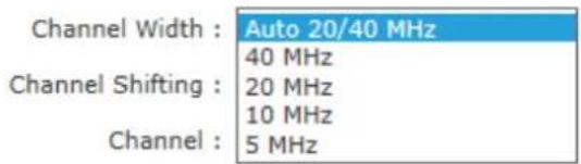
Figure 2-21 Channel Width
- Channel Width: The default mode is 20/40MHz.
SILVERNET
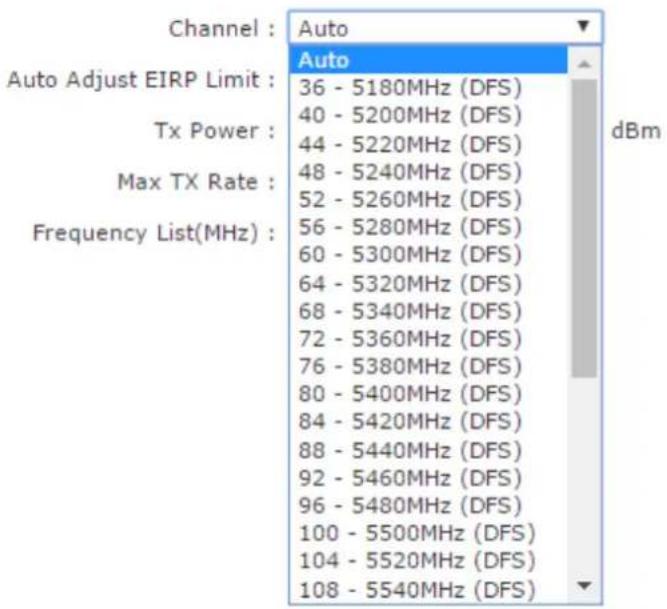
Figure 2-22 Channel
- Channel: This is set to auto channel by default.
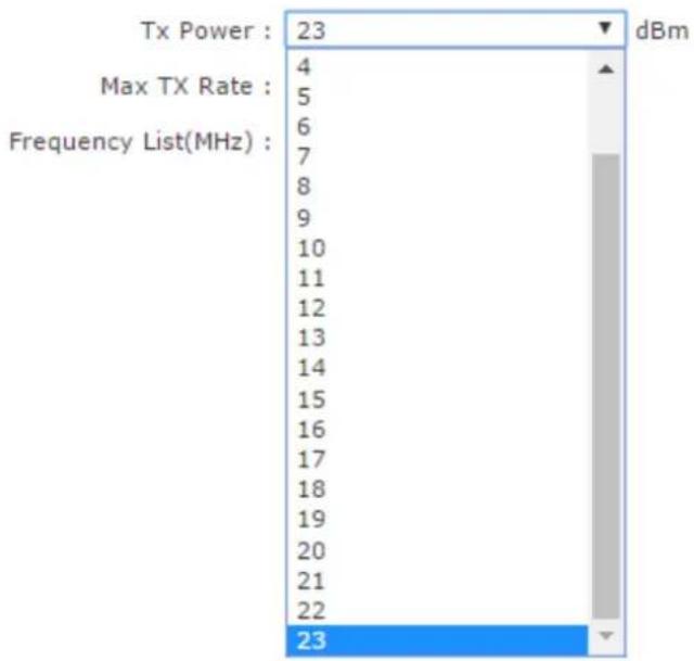
bar
| Category | Value | |---|---| | Tx Power : | 23 | | Max TX Rate : | 4 | | Max TX Rate : | 5 | | Max TX Rate : | 6 | | Max TX Rate : | 7 | | Max TX Rate : | 8 | | Max TX Rate : | 9 | | Max TX Rate : | 10 | | Max TX Rate : | 11 | | Max TX Rate : | 12 | | Max TX Rate : | 13 | | Max TX Rate : | 14 | | Max TX Rate : | 15 | | Max TX Rate : | 16 | | Max TX Rate : | 17 | | Max TX Rate : | 18 | | Max TX Rate : | 19 | | Max TX Rate : | 20 | | Max TX Rate : | 21 | | Max TX Rate : | 22 | | Max TX Rate : | 23 | | Frequency List(MHz) : | | | Frequency List(MHz) : | 23 | dBmFigure 2-23 Tx Power
- Tx Power : The default is 24dBm.
WARNING
Tx power has a different limit for each country. When changing the Tx power the user should follow the regulatory rules.
Transmission power can influence signal strength of the wireless communication. When it transmit distance is long, please increase transmit power intermittently to ensure stronger signal. signal strength.
SILVERNET
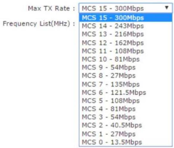
Figure 2-24 Max TX Rate
- Max TX Rate: 2.4GHz/5GHz radio are 2X2 devices, the max support is MCS=15 which is also the default setting.
2.2.2 Advanced Wireless Settings
Advanced Settings
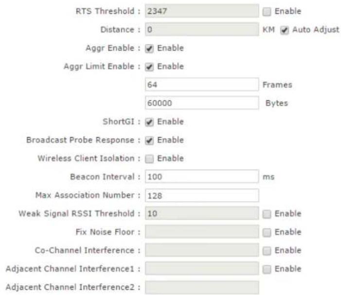
Figure 2-25 RTS Threshold
- RTS Threshold: The default setting for the RTS threshold is 2347. However this is not enabled by default.
- Fragmentation Threshold : This is not set by default
SILVERNET
- Distance: ACK _timeout is enabled by default you can set distance between AP and STA allowing the link to be more stable when it is transmitting in long distance, proper adjustment can improve throughput.
- Aggr Enable : Enable to start function of A-MPDU this is set to enable by default.
- Aggr limit Enable: used o set the sending limit function of A-MPDU, this is set to enable by default. The max Aggr packet is 64 units. The max Aggr length is 60000 bytes.
2.2.3 WMM Settings
WMM Settings
Enable
AP EDCA Parameter :
AC Type
| AC_BK | 7 |
| AC_BE | 3 |
| AC_VI | 1 |
| AC_VO | 1 |
ECWmin
| 4 |
| 4 |
| 3 |
| 2 |
ECWmax
| 10 |
| 6 |
| 4 |
| 3 |
TXOP Limit
| 0 |
| 0 |
| 97 |
| 47 |
No ACK
STA EDCA Parameter :
AC Type
| AC_BK | 7 |
| AC_BE | 3 |
| AC_VI | 2 |
| AC_VO | 2 |
ECWmin
| 4 |
| 4 |
| 3 |
| 2 |
ECWmax
| 10 |
| 10 |
| 4 |
| 3 |
TXOP Limit
| 0 |
| 0 |
| 94 |
| 47 |
Figure 2-26 WMM Settings
WMM Settings is used to set AP EDCA parameter and ST EDCA parameter.
- AC Type: Access control, the Enhance Distributed Channel Access (EDCA) has 4 AC types. Each AC type has a specific set of parameters that they follow.
- AIFSN : Arbitration Inter-Frame Space Number. This allows for AC types to be given higher or lower priority.
- ECWmin/max : CW means content window. This can be set according to the traffic expected in each AC. Wider window is set for higher traffic.
- TXOP Limit : TXOP means Tx opportunity. This is a bounded time window in which a unit can send as many frames as possible.
- No ACK: No ACK frames do not have to be acknowledged used to avoid retransmission.
SILVERNET
2.3 WIRELESS Page
The wireless Page is used to set up the WLAN of the AP or the relevant parameters for the Station allowing the station to connect to the AP
2.3.1 AP/AP WDS Mode
When the unit is set as AP/AP WDS Mode, Wireless Page is shown as Figure 3-12.
1. Wireless Settings
- Wireless1/2/3/4 : The unit can be ser with 4 wireless services, name correctly so they can be distinguished from one another.
- Wireless Availability: Weather the wireless service is enabled or disabled by default the status of Wireless1 is enabled, and Disabled for all others.
- Hide SSID : This can be disabled or enabled. This function allows the link to be hidden from all other wireless equipment. By default this is disabled.
- SSID: In this textbox is where you would type the SSID.
Wireless Settings
Wireless1
Wireless2
Wireless3
Wireless4
Wireless Availability : ● Enable Ⓞ Disabled
Figure 2-27 Wireless Page
SILVERNET
2. Wireless Security
- Security: This is where the security settings of the link can be changed the default setting is WPA2 PSK. WEP security type, as shown Figure 2-27.
Wireless Security
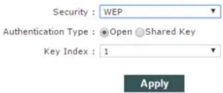
Figure 2-28 WEP Security Type
- Authentication Type : Set authentication method, the default is set to open.
■ WEP Key Length : Set WEP key length, the default is 64 bit.
Key Type : Set key type, the default is ASCII type.
■ WEP Key : Enter WEP key.
Key Index : Choose key index, the default is 1.
WPA/WPA2 security type, as shown Figure 2-28.
Wireless Security
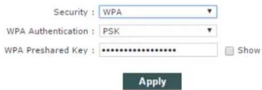
Figure 2-29 WPA security type
Wireless Security
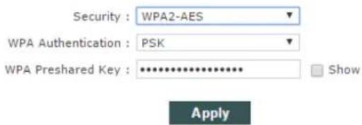
Figure 2-30 WPA2 security type
WPA Authentication: Set WPA/WPA2 authentication method
■ WPA Preshard Key : Set PSK key of WPA/WPA2.
2.3.2 Station/Station WDS Mode
Wireless settings when the unit is set as Station/Station WDS Mode, Wireless is shown as Figure 2-30.
Wireless Settings
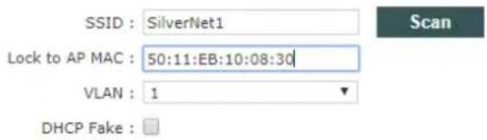
Figure 2-31 Wireless Setting Page
1. Wireless Settings
- SSID: Enter the same SSID as you have in the AP. IF you just enter the SSID and do not lock to AP MAC the station will connect to the strongest signal of the same SSID.
- Lock to AP MAC: Here you will enter the Mac of the partner radio making the radios have to meet two conditions before they connect.
- Scan: The scan button is used to scan for SSID's and available channels, as Figure 2-31.
Scan List :
Note: Site Survey can only scan the channel/frequency supported by current region code.
| MAC Address | SSID | Device Name | Auth_mode | Encryption | Signal / Noise, dBm | Frequency, GHz | Channel | |
| 1. 50:11:EB:10:08:30 | SilverNet1 | SilverNet Echo | -45 / -95 | 5.7 | 140 | Lock to AP | ||
| 2. AC:84:C9:A6:88:CD | BTHub6-WFZC | WPA2 WPS | CCMP | -88 / -95 | 5.18 | 36 | Lock to AP | |
| Scan |
Figure 2-32 Scan List
■ MAC Address: The BSSID address of the wireless service.
- SSID: The BSSID name of the wireless service, also called ESSID.
- Auth_mode: Authentication method of the wireless service.
■ Encryption: The encryption type of the wireless service.
- Signal/Noise: Ssignal strength of the wireless service.
- Frequency : The frequency of the wireless service.
- Channel: The channel of the wireless service.
- Lock to AP: If this button is pressed the unit would lock to the BSSID of this wireless service.
2. Wireless Security
The unit would automatically choose the right encryption type you would need to manually go and
SILVERNET
input the pre shared key to establish connection.
2.4 NETWORK
NETWORK Page is used for setting up the relevant parameters of the network mode. The unit supports
Bridge Mode, SOHO Router Mode and WISP Mode.
SOHO Router Mode and WISP Mode have the same settings page; here is introduction about Bridge
Mode and WISP Mode.
2.4.1 Bridge Mode
Setting of Bridge Mode is shown as Figure 2-32.
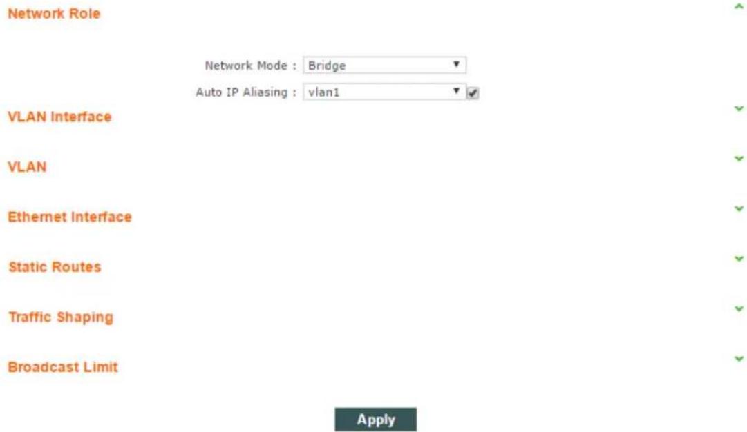
Figure 2-33 Bridge Mode
1. Network Role
■ Network Mode: set current network mode.
- Auto IP Aliasing: When this is enable the unit will be recoverable by the IP address set up in whichever Vlan interface the user inputs into the drop down menu
2. VLAN
- ID: The added VLAN ID.
SILVERNET
■ Describe: The description of a VLAN.
- Untagged Port: Untagged ports of this VLAN.
- Tagged Port: Tagged ports of this VLAN.
- Edit: Edit corresponding VLAN
- Delete: Delete corresponding VLAN.
3. VLAN Interface
ID: VLAN ID.
- Interface: corresponding VLAN interface of VLAN ID.
■ Mode: Access of the IP of the corresponding VLAN interface.
IP/ Mask: IP address and netmask of corresponding VLAN interface.
- Gateway: Gateway of corresponding VLAN interface.
- DHCP: Open DHCP server function of corresponding VLAN interface.
- MTU: MTU of corresponding VLAN interface.
- Edit: Edit corresponding VLAN interface.
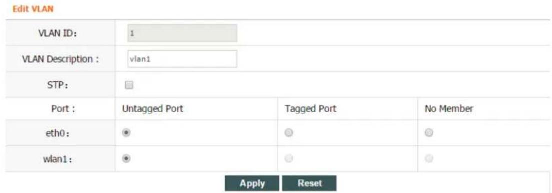
Figure 2-34 Edit VLAN
- VLAN Description: edit the description of the VLAN
- Port: When set to untagged all traffic can flow through the port tagged and untagged. When set to tagged only traffic with the corresponding Vlan ID can pass through the port.
Edit VLAN DHCP Server Not Connected.
| IP : | Static DHCP None | ||
| IP Address : | 192.168.1.2 | Primary DNS : | |
| Netmask : | 255.255.255.0 | Secondary DNS : | |
| Gateway IP : | |||
| MTU: | 1500 | ||
| DHCP Server: | |||
Figure 2-35 Edit VLAN Interface
IP Address: Set static IP address.
■ Netmask: Set netmask of static IP address.
- Gateway IP: Set static gateway address.
■ Primary DNS IP: Set static main DNS address.
■ Secondary DNS IP: Set static backup DNS address.
MTU: Set MTU, the default is 1500 bytes.
- IP Start: Set start IP address of DHCP server
IP End: Set end IP address of DHCP server
- Netmask: Set netmask of DHCP server
- Lease Time: Set lease time of DHCP server
2.4.2 WISP/SOHO Router Mode
WISP/SOHO Router Mode is shown as Figure 2-35.
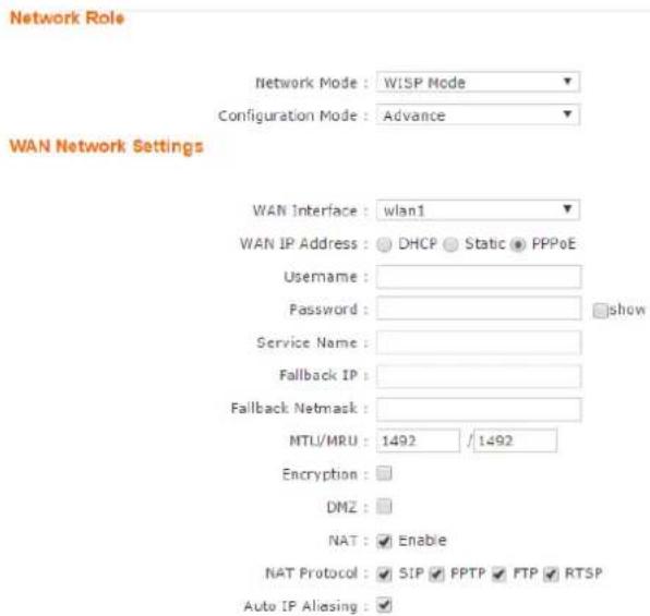
Figure 2-36 Setting Page
1. Network Role
■ Network Mode: Used to set network mode.
2. WAN Network Settings
- WAN IP Address: The WAN IP address can be obtained in three different ways, Static, DHCP and PPPoE negotiation. WISP Mode uses PPPoE to obtain wan IP address
- Username: Set PPPoE connection username.
- Password: Set PPPoE connection password.
■ Service Name: Set PPPoE connection service name. - Fallback IP: Set fallback IP address after PPPoE negotiation failed.
- Fallback Netmask: Set fallback netmask of IP address after PPPoE negotiation failed.
MTU/MRU: Set MTU and MRU PPPoE negotiation. - Encryption: Set MPPE Agreement is enabled when PPPoE negotiation is using Microsoft Point-to-Point Encryption Agreement.
NAT: Set NAT service to "enabled" or "disabled" with the checkbox.
DMZ: Set DMZ service of "enabled" or "disabled" with the checkbox
NAT Protocol: Device supports the following NAT services of SIP, RSTP, FTP and PPTP.
SILVERNET
Static Routes

Figure 2-38 Static Routes
Static Routes is one kind of special routes, manually configured by the administrator.
- Enable: Set the static routes service to enable or disabled.
- Target Network IP: Set the target network IP address.
- Netmask: set the netmask.
- Gateway IP: Set the gateway IP.
- Comment: Comment can be added for corresponding static routes.
■ Action: Add, delete, and edit static routes.
Port Forwarding
| Enabled | Private IP | Port | Type | Source IP/mask | Public IP/mask | Public Port | Comment | Action |
| TCP▼ | Add |
Figure 2-39 Port Forwarding
Port Forwarding comes into effect when network mode is SOHO Router/WISP.
■ Enable: Set the port forwarding to enable or disabled.
- Private IP: Set the forwarded intranet host IP address.
- Private Port: Set the forwarded intranet host protocol a port number.
- Type: Set the forwarded intranet host protocol to either TCP or UDP.
- Source IP/Mask: Set the visiting host source IP and mask.
- Public IP/Mask: Set the forwarded extranet host IP and mask.
■ Public Port: Set the extranet port for intranet host forwarding.
- Comment: Add a comment for corresponding forwarding.
■ Action: Add, delete, and edit corresponding forwarding.
SILVERNET
Traffic Shaping
No DHCP Client.

Figure 2-40 Traffic Shaping
Traffic Shaping is used to limit ingress and egress bandwidth on the Ethernet port and the wireless interface.
- Enable: set traffic shaping service to enable or disabled for the corresponding interface.
- Ingress: ingress traffic is traffic on the ingressing interface.
- Egress: egress traffic is traffic on the forwarding interface.
- Rate,kbit/s: Set limited max rate.
- Burst,kBytes: Set burst byte length.
■ Action: Add, delete, and edit corresponding rules.
SILVERNET
2.5 SERVICES
Services Page is used for setting safe access, access management and so on, as Figure 2-40.
Web Server
NTP Client
Dynamic DNS
Wireless Client Rate Limit
Black&White List
Apply
Figure 2-41 Services
2.5.1 Web Server
Web Server is used to set server port and session timeout of web server.
Web Server

Figure 2-42 Web Server
- Server Port: Set server port of web service, the default is 80.
- Session Timeout: Set web session timeout, the default is 15 minutes.
SILVERNET
2.5.2 NTP Client
NTP means Network Time Protocol. NTP can set the time as the same on all units.
NTP Client

Figure 2-44 NTP Client
- NTP Client: Set NTP Client service as enable or disabled, the default is set to disabled.
- NTP Server: Set IP address or domain name of NTP Server.
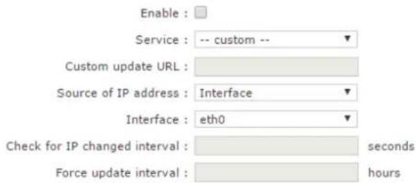
2.5.3 Dynamic DNS
Dynamic DNS
2.5.4 Wireless Client Rate Limit
Wireless Client Rate Limit
Disabled All Clients Classified Clients
All Clients:
CIR(Outbound): 0
CIR(Inbound): 0
CIR: Committed Information Rate(kbps)
Figure 2-46 Client Rate Limit-All Clients
- CIR: CIR means Committed Information Rate in other words bandwidth rate limit, kbps is the unit of measure.
- Outbound: Set the outbound rate limit value this is the limited rate of Transmitting.
- Inbound: Set the inbound speed limit value this is the limited rate of the receiving RF.
SILVERNET
Wireless Client Rate Limit
Disabled All Clients Classified Clients
11n Clients:
CIR(Outbound): 0
CIR(Inbound): 0
11a/11g Clients:
CIR(Outbound): 0
CIR(Inbound): 0
11b Clients:
CIR(Outbound): 0
CIR(Inbound): 0
CIR: Committed Information Rate(kbps)
Figure 2-47 Client Rate Limit-Classified Clients
■ 11n Clients: Set the inbound and outbound rate limit of 802.11n clients.
■ 11a/11g Clients: Set the inbound and outbound rate limit of 802.11a/802.11g clients.
■ 11b Clients: Set the inbound and outbound rate limit of 802.11b clients.
SILVERNET
2.5.5 MAC Control
MAC Control means to restrict Internet access by computer MAC address, and manage access and visit of users by supporting blacklist or white list. Don't open MAC control in the case of the default, that is to say, all computers can visit Internet without limit, as Figure 2-51.
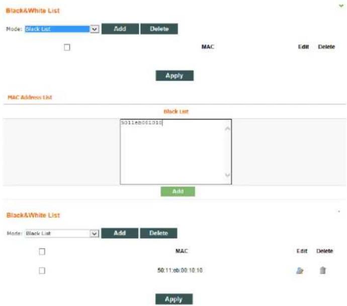
Figure 2-52 MAC Control
- Mode: This can be set to either Blacklist or Whitelist, this will deny or allow specific MAC addresses.
• Mac Address List: Input MAC address, Add.
2.6 SYSTEM
System Page is mainly used for settings relating to device management, as Figure 2-49.
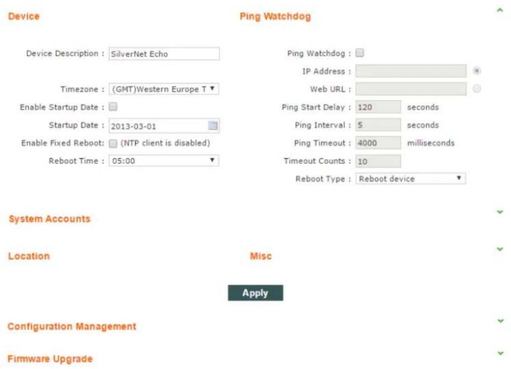
Figure 2-53 System Page
2.6.1 Device
Device
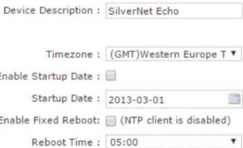
Figure 2-54 Device
■ Device Description: Set the device description.
■ Enable Startup Date: Set to enable startup date, the default is disabled.
SILVERNET
- Startup Date: Set the device startup date.
- Time zone: Set the device time zone.
2.6.2 Ping Watchdog
Ping Watchdog
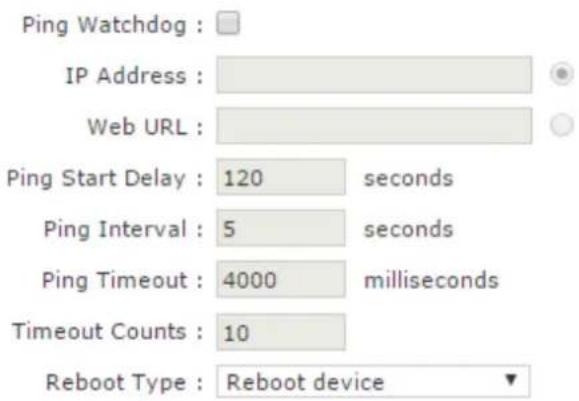
Figure 2-55 Ping Watchdog
2.6.3 System Accounts
System Accounts
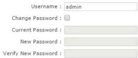
Figure 2-56 System Accounts
- Username: Set the admin username.
■ Current Password: Input current password.
■ New Password: Set a new password. - Verify New Password: Verify the new password.
SILVERNET
2.6.4 Configuration Management
Location
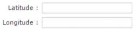
Figure 2-57 Location Page
- Latitude: Set device latitude.
- Longitude: Set device longitude.
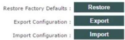
Configuration Management
Reboot : Reboot
Figure 2-58 Configuration Management
Restore Factory-default Settings
Note: Restore factory-default settings will reset the settings to factory-default after the device reboots.
Figure 2-59 Restore Factory-default settings
import the configuration file
Note: Restore configuration will delete the current settings and reboot the device.
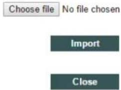
Figure 2-60 Import the configuration file
SILVERNET
Device Reboot
Note: Any configuration changes that have not been saved will be lost after the system reboots.
Reboot after save
Reboot
Cancel
Figure 2-61 Device Reboot
- Restore Factory defaults: Restore to factory default.
- Export Configuration: Export current configuration.
- Import Configuration: Import configuration into device.
■ Reboot: Reboot device.
2.6.5 Firmware upgrade
Firmware Upgrade
Version : v1.343.1 (21062017)
Update File : Choose file No file chosen
Save Configuration : √
Flash : 16M
Upgrade
Figure 2-62 Firmware Upgrade
Firmware upgrade is used for upgrading software of the device.
■ Version: displays the current version of firmware.
- Update File: Choose update file.
SILVERNET
2.7 Tools
2.7.1 Ping
The ping test is usually used for measuring the network latency and performance.
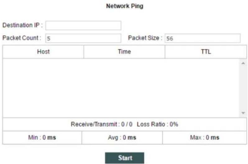
Figure 2-63 Network Ping
- Destination IP: The target IP address.
- Packet Count: Number of the pings.
- Packet Size: Define the ping/ICMP packet size, the larger size of the packet the higher latency for the ping.
2.7.2 Traceroute
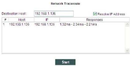
Figure 2-64 Network Traceroute
- Destination host: The target IP address/domain for tracing.
- Resolve IP Address: Allows IP address to be entered
2.7.3 Site survey
Scan List :
Note: Site Survey can only scan the channel/frequency supported by current region code.

| MAC Address | SSID | Device Name | Auth_mode | Encryption | Signal / Noise, dBm | Frequency, GHz | Channel | |
| 1. 50:11:EB:10:08:30 | SilverNet1 | SilverNet Echo | -45 / -95 | 5.7 | 140 | Lock to AP | ||
| 2. AC:84:C9:A6:88:CD | BTHub6-WFZC | WPA2 WPS | CCMP | -88 / -95 | 5.18 | 36 | Lock to AP | |
| Scan | ||||||||
Figure 2-65 Scan List
■ MAC Address: BSSID address of the wireless service.
- SSID: BSSID name of wireless service, also called ESSID.
- Auth_mode: Authentication method of the wireless service.
■ Encryption: Encryption type of the wireless service.
- Signal/Noise: Signal strength and noise of wireless service.
■ Frequency : The frequency of the wireless service.
■ Channel: The channel of the wireless service.
2.7.4 Speed Test
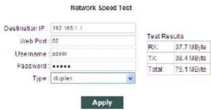
Figure 2-66 Network Speed Test
- Destination IP : The target IP address is often the IP of the opposite radio.
- Web Port: Default is 80
- Username: Default is admin
- Password: Default is admin
■ Type: Transmit/receive/duplex speed performance of wireless
■ Test Result: The end of test results.
SILVERNET
Contact Us
SilverNet Ltd
2 Vermont Place
Tongwell
Milton Keynes
MK15 8JA
Online Resources
If you need any further assistance go to our website download centre:
www.silvernet.com/downloadcentre/
View our troubleshooting guide:
http://www.silvernet.com/support/frequently-asked-questions/
Use our online ticket support:
www.silvernet.com/support/
Email us at support@silvernet.com
www.silvernet.com
CE Mark Warning

SILVERNET
This is a class B product. In a domestic environment, this product may cause radio interference, in which case the user may be required to take adequate measures.
- SIL ECHO BS/ST
- User Manual
- Radio frequency Interference Requirements
- FCC Warning
- RF Exposure Requirements
- SILVERNET
- CE Statement
- Copyright Information
- Contents
- Radio frequency Interference Requirements ....2
- Installing the radio ....6
- Software Configuration 12
- Radio Page 22
- WIRELESS Page....27
- NETWORK....30
- SERVICES....36
- SYSTEM 40
- Tools....44
- Contact Us 46
- Online Resources....46
- Installing the radio
- Instructions before installing
- Installation
- NOTE
- Powering up the Radio
- Accessing the radio
- Software Configuration
- Main Page
- Status-WIRELESS
- Status-NETWORK
- Network Mode
- LAN
- Status-SYSTEM
- Monitor-Throughput
- Monitor-Interfaces
- Monitor-ARP List
- Monitor-STA Stats
- Monitor-AP Stats
- Monitor-Routes
- Radio Page
- Basic Wireless Settings
- WARNING
- Advanced Wireless Settings
- Advanced Settings
- WMM Settings
- WMM Settings
- WIRELESS Page
- AP/AP WDS Mode
- Wireless Settings
- Wireless Settings
- Wireless1
- Wireless Security
- Wireless Security
- Station/Station WDS Mode
- Scan List :
- NETWORK
- Bridge Mode
- Network Role
- VLAN
- VLAN Interface
- WISP/SOHO Router Mode
- WAN Network Settings
- Static Routes
- Port Forwarding
- Traffic Shaping
- SERVICES
- Web Server
- NTP Client
- Dynamic DNS
- Wireless Client Rate Limit
- Wireless Client Rate Limit
- MAC Control
- SYSTEM
- Device
- Device
- Ping Watchdog
- Ping Watchdog
- System Accounts
- System Accounts
- Configuration Management
- Location
- Configuration Management
- Restore Factory-default Settings
- import the configuration file
- Device Reboot
- Firmware upgrade
- Firmware Upgrade
- Tools
- Ping
- Traceroute
- Host IP Responses
- Site survey
- Speed Test
- Contact Us
- SilverNet Ltd
- Online Resources
- If you need any further assistance go to our website download centre:
- CE Mark Warning
Brand : SilverNet
Model : ECHO-ST
Category : Access Point