SIL 4.9 MICRO 95-PCP - Wi-Fi Router SilverNet - Free user manual and instructions
Find the device manual for free SIL 4.9 MICRO 95-PCP SilverNet in PDF.


| Product Type | Point-to-Point Wireless Link (Outdoor Radio) |
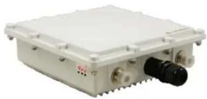
| Model | SIL MICRO 95-PCP |
| Brand | SilverNet |
| Frequency Band | 5 GHz |
| User Data Throughput | 95 Mbps |
| Range | Up to 2 km (point-to-point) |
| Antenna | Built-in dual antenna, 15 dBi gain |
| Security | WEP, WPA, WPA2, AES-256 encryption |
| Management | Web GUI, SilverView NMS |
| Power Supply | Power over Ethernet (PoE) via included injector |
| Enclosure | Weatherproof, compact design |
| Mounting | High-quality lightweight mounting brackets included |
| Cable Length (max) | 100 m from PoE injector to network device |
| Compliance | CE, FCC (typical for such devices) |
| Operating Temperature | -20°C to 60°C (typical outdoor) |
| Default SSID | silvernetwireless |
| Default Password | silvernetwireless (WPA2 key) |
| Default IP Address (Device 1) | 192.168.0.228 |
| Default IP Address (Device 2) | 192.168.0.229 |
| Default Admin Username | admin |
| Default Admin Password | password |
Frequently Asked Questions - SIL 4.9 MICRO 95-PCP SilverNet
User questions about SIL 4.9 MICRO 95-PCP SilverNet
0 question about this device. Answer the ones you know or ask your own.
Ask a new question about this device
Download the instructions for your Wi-Fi Router in PDF format for free! Find your manual SIL 4.9 MICRO 95-PCP - SilverNet and take your electronic device back in hand. On this page are published all the documents necessary for the use of your device. SIL 4.9 MICRO 95-PCP by SilverNet.
USER MANUAL SIL 4.9 MICRO 95-PCP SilverNet
Wireless Application Setups
PRO RANGE
■ Operates at the 5GHz RF band
■ Practical data-rate : 95 Mbit/Sec of user data throughput. Duplex
Gigabit interface 240/500/1000 Mbit/Sec of user data throughput
■ Point-To-Point up to 1KM, 2KM, 6KM, and 60KM
- Compact design
■ Weatherproof
■ High quality lightweight mounting brackets supplied
■ Power over Ethernet
■ Up to 256 AES Security

natural_image
Close-up of a metallic padlock with blue cables, no visible text or symbolsSecure Transmission
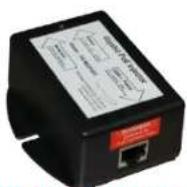
Gigabit PoE Injector

natural_image
Metal mechanical bracket assembly with mounting bracket set (no text or symbols on the component itself)Point To Point Advantages

natural_image
City skyline with modern skyscrapers and a grassy park in the foreground, featuring orange circular graphics overlay (no readable text or symbols)Maximum Bandwidth Highest Stability
PRO RANGE – 95Mbps
PICO-1KM

• 12dBi Built in Dual Antenna
95Mbps
- Point-to-Point
• Equipped with POE
WEP, WPA, WPA2
WEB Management
MICRO-2KM
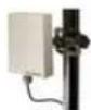
• 15dBi Built in Dual Antenna
95Mbps
- Point-to-Point
- Equipped with POE
WEP, WPA, WPA2
WEB Management
LTE-6KM
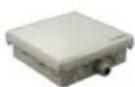
• 18dBi Built in Dual Antenna
95Mbps
- Point-to-Point
• Equipped with POE
WEP, WPA, WPA2
WEB Management
MAX-60KM
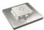
• 23dBi Built in Dual Antenna
95Mbps
- Point-to-Point
• Equipped with POE
• WEP, WPA, WPA2
• WEB Management
PRO RANGE - 240Mbps
MICRO 240 - 2KM
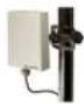
• 15dBi Built in Dual Antenna
• 240Mbps
- Point-to-Point
• Equipped with POE
• WEP, WPA, WPA2
• WEB Management
LITE 240-6KM
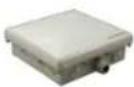
18dBi Built in Dual
Antenna
240Mbps
- Point-to-Point
• Equipped with POE
WEP, WPA, WPA2
• WEB Management
MAX 240 - 60KM
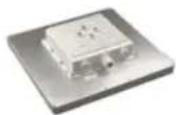
• Dual 23dBi Built in
Dual Antenna
• 240Mbps
- Point-to-Point
• Equipped with POE
WEP, WPA, WPA2
- WEB Management
PRO RANGE - 500Mbps
LITE 500 - 6KM
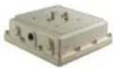
• 18dBi Built in Dual Antenna
500Mbps
- Point-to-Point
• Equipped with POF
• WEP, WPA, WPA2
• WEB Management
MAX 500 - 60KM
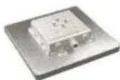
• Dual 23dBi Built in Dual Antenna
500Mbps
- Point-to-Point
• Equipped with POE
• WEP, WPA, WPA2
• WEB Management
PRO RANGE – 1000Mbps
MAX 1000 - 20KM
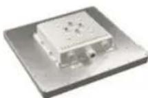
- TRI 18dBi Built in Antenna
1000Mbps - Point-to-Point
• Equipped with POE
WEP, WPA, WPA2 - WEB Management
Point to Point System Antenna Beamwidths
30^
20^
10^
2KM
MICRO
6KM
LITE
60 KM
MAX
= Radio
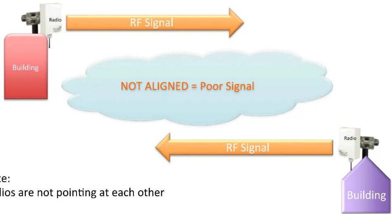
Antenna Alignment is Important
flowchart
graph LR
    A["Building"] -->|RF Signal| B["Building"]
    B -->|RF Signal| A
    note["NOT ALIGNED = Poor Signal"]
    note --> note1["e: ios are not pointing at each other"]
Note:
Radios are not pointing at each other
Antenna Alignment is Important
flowchart
graph LR
    A["Building"] -->|RF Signal| B["RF Signal"]
    B -->|ALIGNED = Good signal| C["Building"]
    style A fill:#FFD700,stroke:#333
    style C fill:#8B24A6,stroke:#333
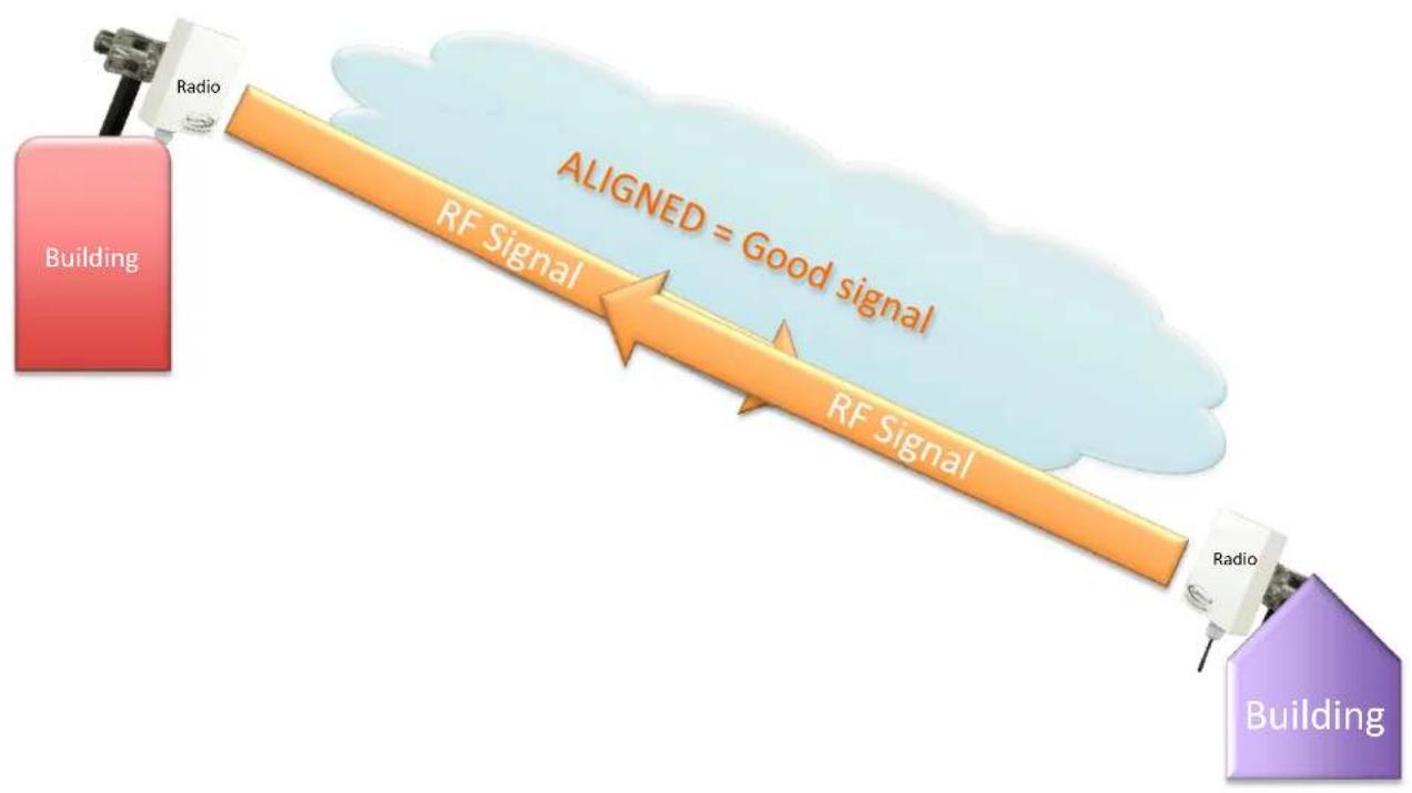
Antenna Alignment is Important
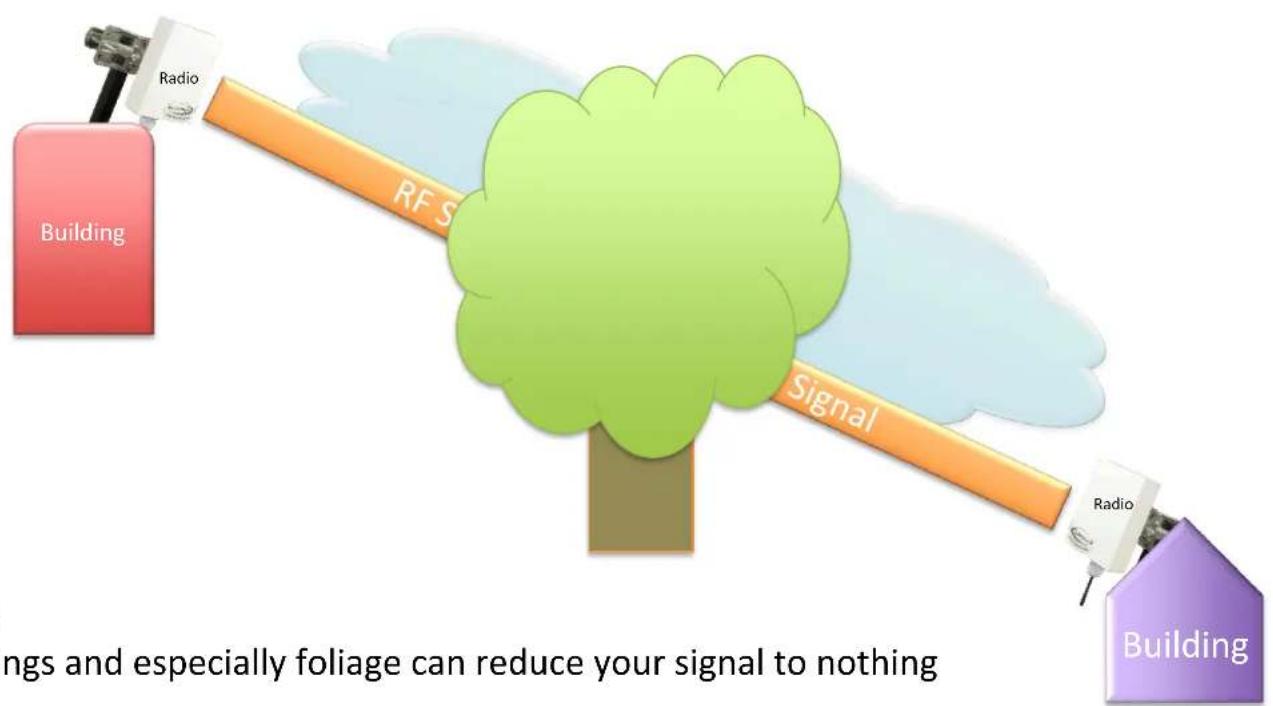
Note:
Buildings and especially foliage can reduce your signal to nothing
Point to Point Wireless Link for a Network
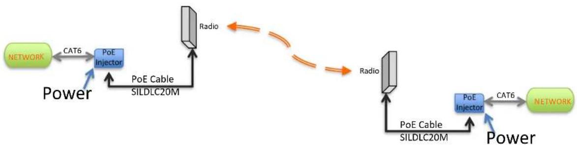
Note: Maximum Cable length to a network device from the radio is 100m
The PoE injector can be fitted anywhere within this length it only adds power to the cable for the radio.
Radios can be powered from a PoE switch, 100m maximum network cable length rules still apply.
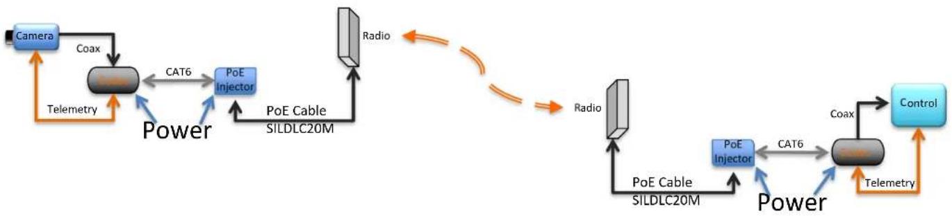
Point to Point wireless Link Single analogue camera via ip encoder and decoder
flowchart
graph TD
    A["Camera"] -->|Telemetry| B["Power"]
    B -->|CAT6| C["PoE Injector"]
    C -->|PoE Cable SILDLC20M| D["Radio"]
    D --> E["Control"]
    E -->|Telemetry| F["Power"]
    F -->|CAT6| G["PoE Injector"]
    G --> H["PoE Cable SILDLC20M"]
    H --> I["Radio"]
    I --> J["Control"]
    J --> K["Telemetry"]
    K --> L["Power"]
    L --> M["Coax"]
    M --> N["Control"]
Note for IP cameras :
■ The codec is not required at the camera end
■ Usually the Control is IP so no codec is required here either
■ Telemetry will pass seamlessly
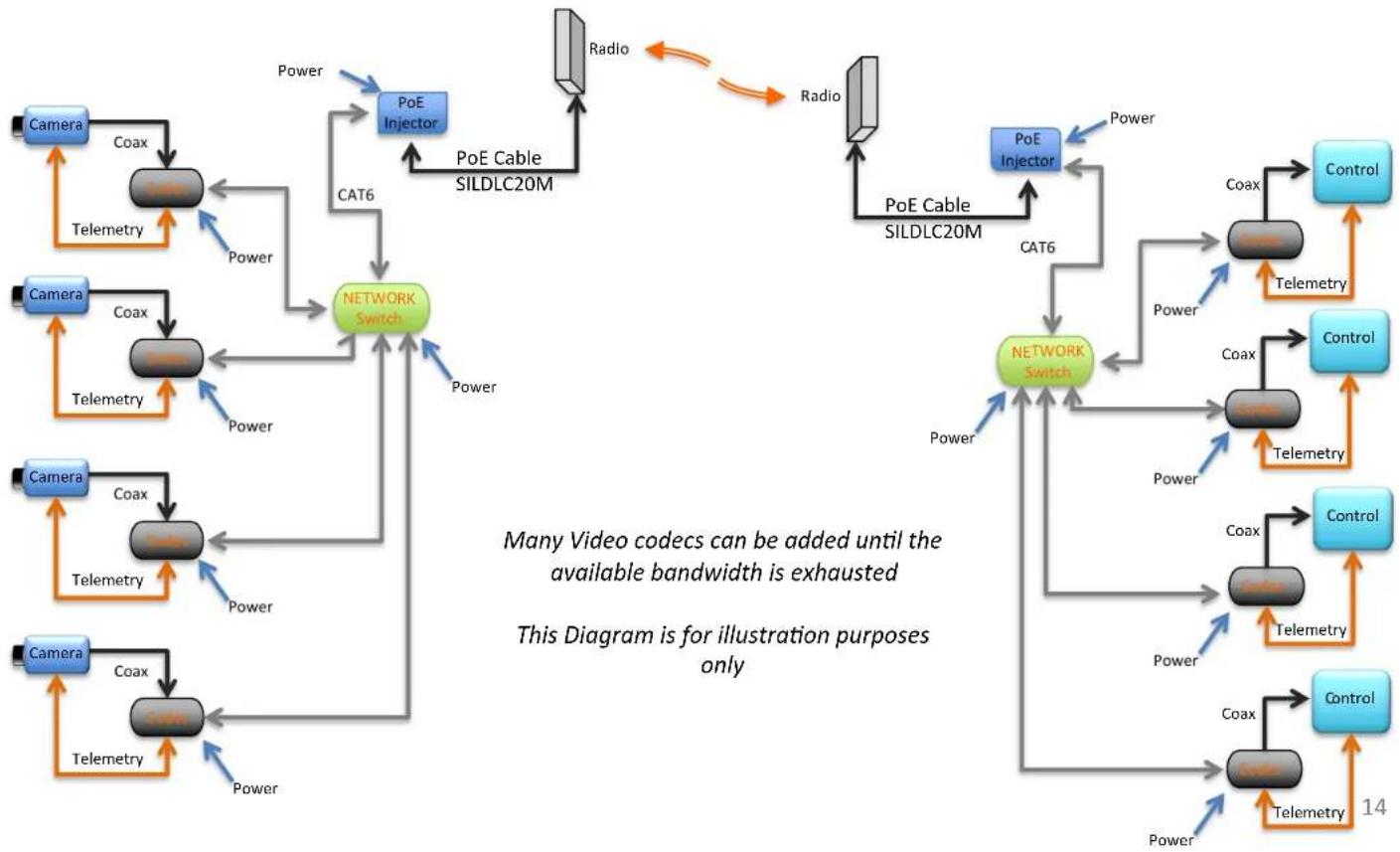
Point to Point Wireless Link Multiple analogue cameras via IP encoder and decoder
flowchart
graph TD
    subgraph_Network_Switch["Network Switch"]
        A["Camera"] -->|Coax| B["Coax"]
        B --> C["Telemetry"]
        C --> D["Network"]
        E["Camera"] -->|Coax| F["Telemetry"]
        F --> G["Telemetry"]
        G --> H["Network"]
    end

    subgraph_Control_Switch["Control"]
        I["Control"] --> J["Control"]
        J --> K["Telemetry"]
        K --> L["Network"]
        M["Control"] --> N["Control"]
        N --> O["Telemetry"]
        O --> P["Network"]
    end

    A -->|Power| Q["PoE Injector"]
    Q --> R["POE Cable SILDLC20M"]
    R --> S["Radio"]
    S --> T["Radio"]
    T --> U["PoE Cable SILDLC20M"]
    U --> V["Network Switch"]
    V --> W["Power"]
    W --> X["Telemetry"]
    X --> Y["Network Switch"]
    Y --> Z["Power"]
    Z --> AA["Telemetry"]
    AA --> AB["Network Switch"]

    subgraph_Video_Codes["Many Video codecs can be added until the available bandwidth is exhausted"]
        AC["This Diagram is for illustration purposes only"]
    end
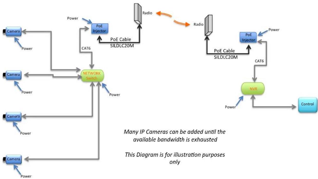
Point to Point Wireless Link with Multiple IP cameras
flowchart
graph TD
    A["Camera"] -->|Power| B["Network Switch"]
    C["Camera"] -->|Power| B
    D["Camera"] -->|Power| B
    E["Camera"] -->|Power| B
    F["Radio"] -->|Power| G["SILDLC20M Cable"]
    H["POE Injector"] -->|CAT6| B
    I["POE Cable"] -->|Radio| G
    J["POE Injector"] -->|CAT6| K["NVR"]
    L["Control"] --> K
    style B fill:#99ccff,stroke:#333
    note bottom
        Many IP Cameras can be added until the available bandwidth is exhausted
        This Diagram is for illustration purposes only
    end
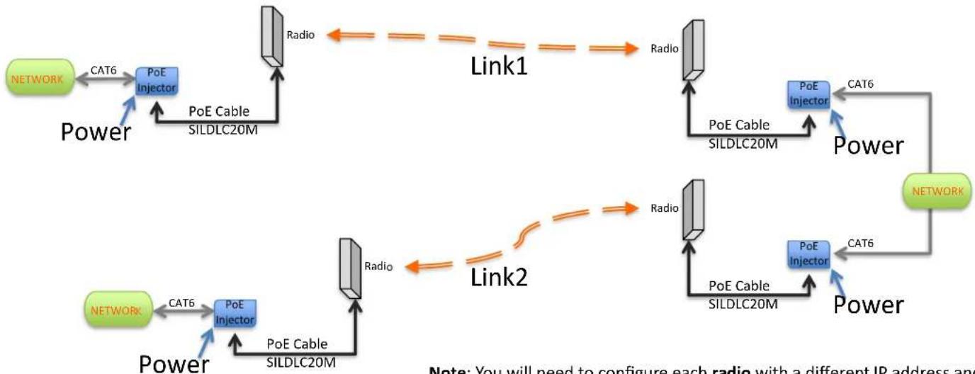
Point to point Wireless Link Repeater for a Network
flowchart
graph TD
    A["NETWORK"] -->|CAT6| B["PoE Injector"]
    B -->|PoE Cable SILDLC20M| C["Radio"]
    C --> D["Link1"]
    D --> E["Radio"]
    E --> F["PoE Injector"]
    F -->|CAT6| G["POWER"]
    G --> H["NETWORK"]
    H -->|CAT6| I["PoE Injector"]
    I --> J["Power"]
    J --> K["Link2"]
    K --> L["Radio"]
    L --> M["PoE Injector"]
    M --> N["Power"]
    N --> O["Network"]
    O --> P["PoE Injector"]
    P --> Q["Power"]
    Q --> R["Network"]
Note: You will need to configure each radio with a different IP address and each link with a different wireless name.
For example:
Link1 IP addresses 192.168.0.200 / 201 and SSID = LINK1
Link2 IP addresses 192.168.0.202 / 203 and SSID = LINK2
and so on. You can do this via quick config in our SilverView software or the web gui of each radio.
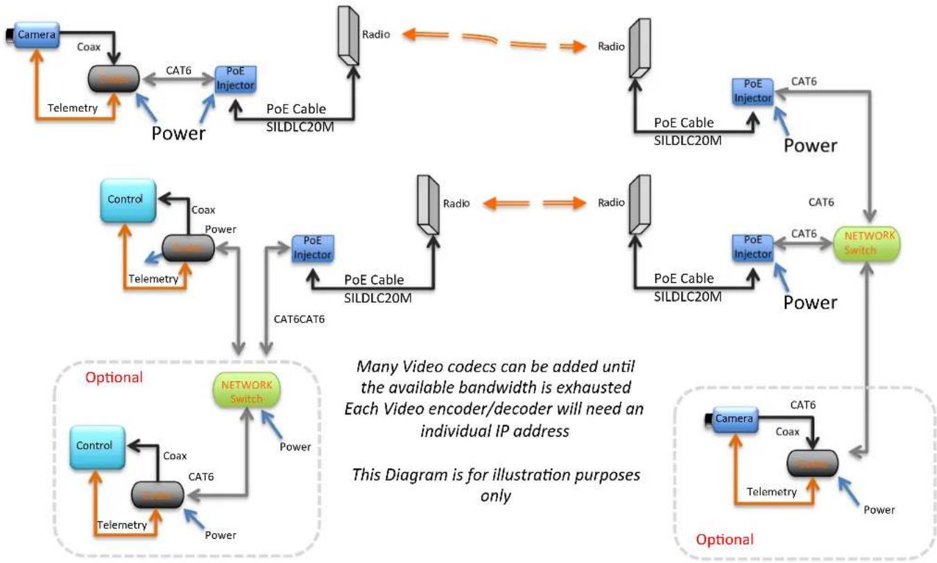
Point to Point wireless link Repeater Single analogue camera via IP encoder and decoder
flowchart
graph TD
    subgraph Power
        A["Camera"] -->|Coax| B["Power"]
        B -->|CAT6| C["PoE Injector"]
        C --> D["Radio"]
        D --> E["Network Switch"]
        E --> F["Optional"]
    end

    subgraph Power_Cable
        G["Control"] -->|Telemetry| H["Power"]
        H --> I["PoE Injector"]
        I --> J["Radio"]
        J --> K["Network Switch"]
        K --> L["Optional"]
    end

    subgraph Power_Cable_SILDLC20M
        M["PoE Injector"] --> N["Power"]
        N --> O["Network Switch"]
        O --> P["Optional"]
    end

    subgraph Power_Cable_SILDLC20M_PoE
        Q["PoE Cable SILDLC20M"] --> R["Power"]
        R --> S["Network Switch"]
        S --> T["Optional"]
    end

    subgraph Power_Cable_SILDLC20M_PoE_Cable
        U["PoE Cable SILDLC20M"] --> V["Power"]
        V --> W["Network Switch"]
        W --> X["Optional"]
    end

    style Power_Cable_SILDLC20M_PoE_Cable_SILDLC20M_1 fill:#f9f,stroke:#333
    style Power_Cable_SILDLC20M_PoE_Cable_SILDLC20M_2 fill:#f9f,stroke:#333
    style Power_Cable_SILDLC20M_PoE_Cable_SILDLC20M_3 fill:#f9f,stroke:#333
    style Power_Cable_SILDLC20M_PoE_Cable_SILDLC20M_4 fill:#f9f,stroke:#333
    style Power_Cable_SILDLC20M_PoE_Cable_SILDLC20M_5 fill:#f9f,stroke:#333
    style Power_Cable_SILDLC20M_PoE_Cable_SILDLC20M_6 fill:#f9f,stroke:#333
    style Power_Cable_SILDLC20M_PoE_Cable_SILDLC20M_7 fill:#f9f,stroke:#333
    style Power_Cable_SILDLC20M_PoE_Cable_SILDLC20M_8 fill:#f9f,stroke:#333
    style Power_Cable_SILDLC20M_PoE_Cable_SILDLC20M_9 fill:#f9f,stroke:#333
    style Power_Cable_SILDLC20M_PoE_Cable_SILDLC20M_10 fill:#f9f,stroke:#333
SilverNet Hardware
What's in the box?
- LINK – PICO, MICRO, LITE, MAX
■ 2 x Radios (Built in Antennas)
■ 2 x PoE Injectors (Gigabit for 240, 500,1000)
■ 2 x Mounting Brackets
Ordering a Point to Point Link
PICO 95 up to 1KM, 95Mbps SIL PICO 95-PCP
MICRO 95
up to 2KM, 95Mbps
SIL MICRO 95-PCP
MICRO 240
up to 2KM, 240Mbps
SIL MICRO 240-PCP
LITE 95
up to 6KM, 95Mbps
SIL LITE 95-PCP
LITE 240
up to 6KM, 240Mbps
SIL LITE 240-PCP
LITE 500
up to 6KM, 500Mbps
SIL LITE 500-PCP
MAX 95
up to 60KM, 95Mbps
SIL MAX 95-PCP
MAX 240
up to 60KM, 240Mbps
SIL MAX 240-PCP
MAX 500
up to 60KM, 500Mbps
SIL MAX 500-PCP
Now Add:
10, 20, 50, 90 m Downlink cable – SIL DLCXXM
*1 Per Radio
PURCHASE SILVERNET PRODUCTS VIA OUR DISTRIBUTION AGENTS
For further details about your nearest distributor please contact us for a list of approved SilverNet Distributors
Point To Multipoint Advantages

Reduced Cost Shared Bandwidth
PRO RANGE – 500Mbps
BASE 500 90 - 2KM
- 90° Sector Antenna
500Mbps - Point-to-Point
■ Equipped with POE
■ WEP, WPA, WPA2 - WEB Management
BASE 500 360 - 1KM
■ 360° Sector Antenna
500Mbps
- Point-to-Point
- Equipped with POE
■ WEP, WPA, WPA2
■ WEB Management
BASE 500 - MP
■ Dual Ntype Ports for external Antenna
500Mbps
- Point-to-Point
- Equipped with POE
■ WEP, WPA, WPA2
■ WEB Management
SilverNet Hardware
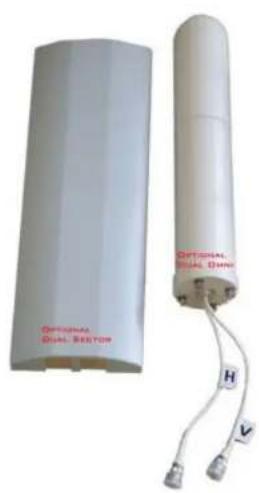
BASE 500 Optional Antenna
- 360° Omni Antenna – Up To 1500m CLOS
• 90° Sector Antenna- Up To 5Km CLOS - 120^ Sector antenna – Up To 5Km CLOS
Sector Antenna
natural_image
Two white electronic devices with red labels: one labeled 'OPTIONAL DUAL SECTOR' and the other 'OPTIONAL DUAL OWNER', connected by wires (H and V).Omni Antenna
natural_image
White rectangular electronic device with black connectors and a metallic connector (no visible text or symbols)Antenna connectors
BASE 500 Antenna Beamwidth and Range
120^
Sector
Antenna
360°
Omni
Antenna
1.5KM
Radius
5KM
Range
The BASE 500 can be
fitted with either a 360°
Omni or a 120°/90°
Sector antenna
depending on your
requirements.
90°
Sector
Antenna
= Radio
Multipoint System Omni Antenna
360°
Omni
1.5KM
NOT ALIGNED = Poor Signal
Radius
The BASE is fitted with a 360^ Omni, however the Omni cannot be tilted so all remote radios need to be mounted at a similar height.
Sector antennas can be tilted.
Radio
= Radio
Point to Multipoint Wireless Link For a Network
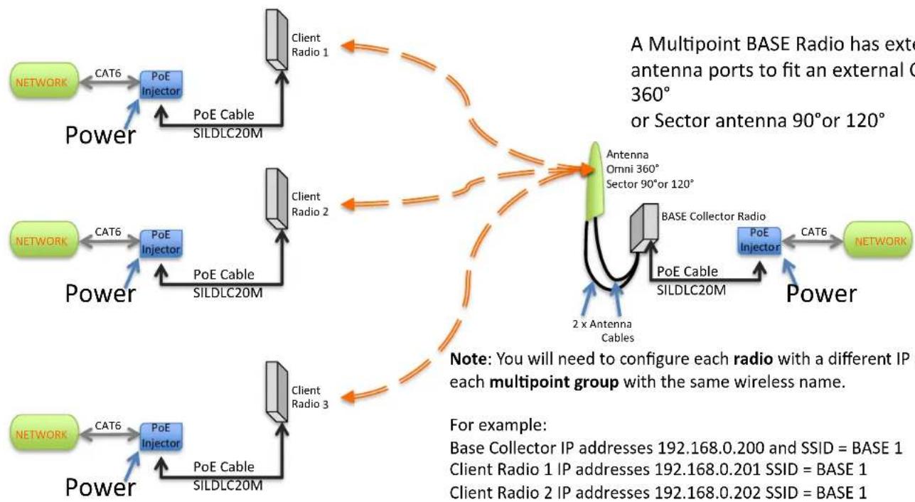
flowchart
graph TD
    subgraph Power
        A["NETWORK"] -->|CAT6| B["PoE Injector"]
        B --> C["Client Radio 1"]
        C --> D["Client Radio 2"]
        D --> E["Client Radio 3"]
        E --> F["Network"]
    end

    subgraph Power
        G["NETWORK"] -->|CAT6| H["PoE Injector"]
        H --> I["Client Radio 2"]
        I --> J["Client Radio 3"]
        J --> K["Network"]
    end

    subgraph Power
        L["NETWORK"] -->|CAT6| M["PoE Injector"]
        M --> N["Client Radio 3"]
        N --> O["Client Radio 2"]
        O --> P["Network"]
    end

    note1["A Multipoint BASE Radio has exte antenna ports to fit an external C 360° or Sector antenna 90° or 120°"]
    note2["Note: You will need to configure each radio with a different IP and each multipoint group with the same wireless name."]
    note3["For example: Base Collector IP addresses 192.168.0.200 and SSID = BASE 1\nClient Radio 1 IP addresses 192.168.0.201 SSID = BASE 1\nClient Radio 2 IP addresses 192.168.0.202 SSID = BASE 1"]
You can do this via quick Config in our SilverView software or the web gui of each radio.
Point to Multipoint wireless Link Multiple analogue cameras via ip encoder and decoder
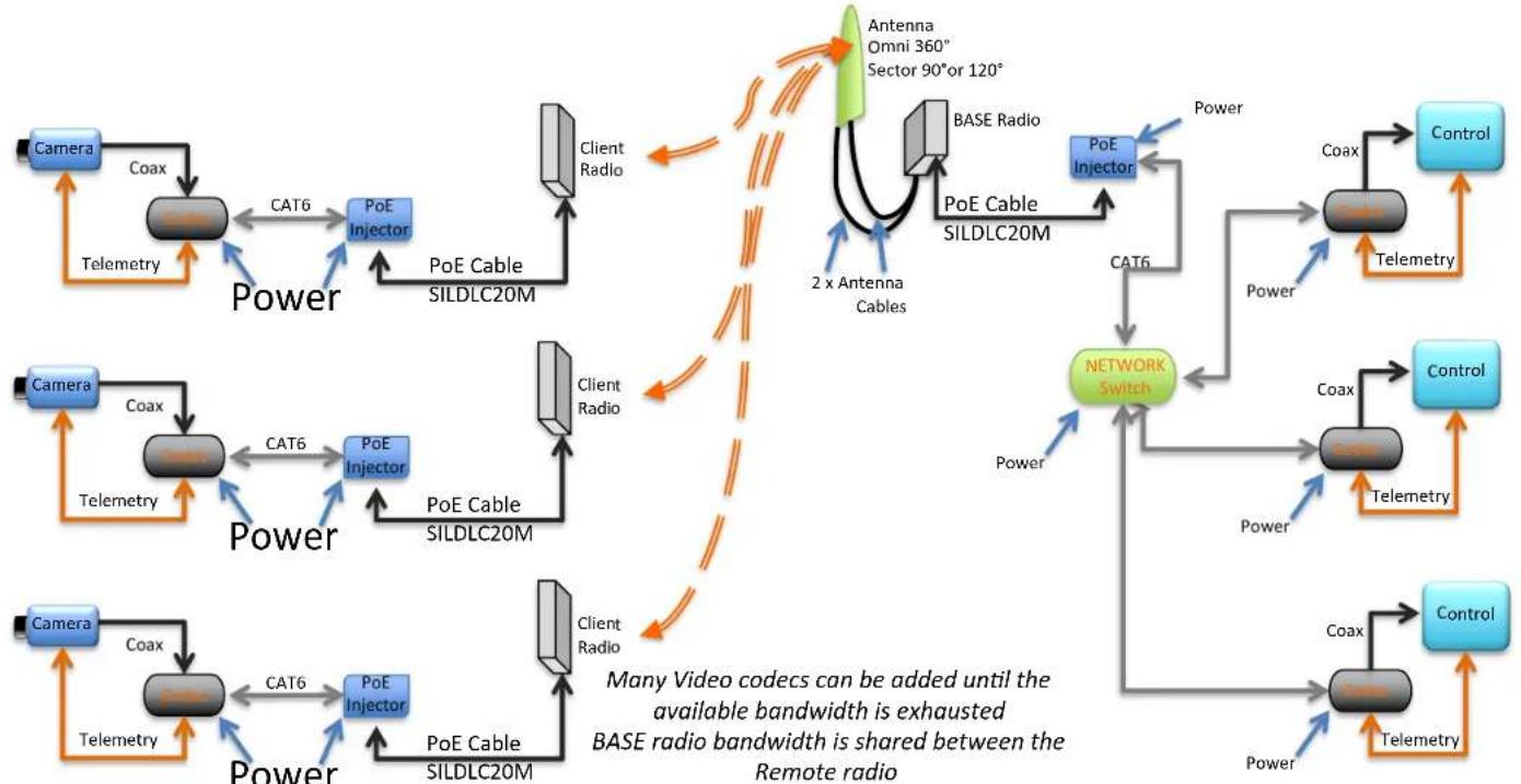
flowchart
graph TD
    subgraph Power
        A["Camera"] -->|Coax| B["Power"]
        B -->|CAT6| C["PoE Injector"]
        C --> D["Client Radio"]
        D --> E["POE Cable SILDLC20M"]
        E --> F["Network Switch"]
        F --> G["Control"]
    end

    subgraph Power
        H["Camera"] -->|Coax| I["Power"]
        I -->|CAT6| J["PoE Injector"]
        J --> K["Client Radio"]
        K --> L["POE Cable SILDLC20M"]
        L --> M["Network Switch"]
        M --> N["Control"]
    end

    subgraph Power
        O["Camera"] -->|Coax| P["Power"]
        P -->|CAT6| Q["PoE Injector"]
        Q --> R["Client Radio"]
        R --> S["POE Cable SILDLC20M"]
        S --> T["Network Switch"]
        T --> U["Control"]
    end

    subgraph Power
        V["Antenna Omni 360° Sector 90° or 120°"] --> W["POE Cable SILDLC20M"]
        W --> X["Network Switch"]
        X --> Y["Control"]
    end

    style Power fill:#f9f,stroke:#333
    style Power fill:#ccf,stroke:#333
    style Power fill:#cfc,stroke:#333
    style Power fill:#fcc,stroke:#333
    style Power fill:#ffc,stroke:#333
    style Power fill:#cff,stroke:#333
    style Power fill:#ffc,stroke:#333
    style Power fill:#ffc,stroke:#333
    style Power fill:#ffc,stroke:#333
    style Power fill:#ffc,stroke:#333
    style Power fill:#ffc,stroke:#333
    style Power fill:#ffc,stroke:#333
    style Power fill:#ffc,stroke:#333
    style Power fill:#ffc,stroke:#333
    subgraph NetworkSwitch
        X
        Y
    end

    note right of F: Many Video codecs can be added until the available bandwidth is exhausted. BASE radio bandwidth is shared between the Remote radio.
    note right of F: Many Video codecs can be added until the available bandwidth is exhausted. BASE radio bandwidth is shared between the Remote radio.
This Diagram is for illustration purposes only
SilverNet Hardware
What's in the box?
- BASE 500 90
■ 1 x Radio with integrated 90° Sector antenna
■ 1 x PoE Injector (Gigabit)
■ 1 x Mounting Brackets Set
BASE 500 360
■ 1 x Radio with integrated 360° Sector antenna
■ 1 x PoE Injector (Gigabit)
■ 1 x Mounting Brackets Set
SilverNet Hardware
What's in the box?
BASE 500
■ 1 x Radio (Antenna Required)
■ 1 x PoE Injector (Gigabit)
■ 1 x Mounting Brackets Set
Options
■ 360° Omni Antenna
■ 90° Sector Antenna
■ 120° Sector Antenna
■ 2, 4, 8 m Antenna cable x 2
■ 10, 20, 50, 90m Downlink cable
Ordering a Point to Multipoint AP/BASE
BASE 500
External Antenna, 500Mbps
SIL BASE 500
BASE 500 90
90° Sector Antenna, 500Mbps
SIL BASE 500 90
BASE 500 360
360° Omni Antenna, 500Mbps
SIL BASE 500 360
BASE 500 options:
A. 2, 4, 8 meter Antenna cable (2 req) - SIL4CABXM
B. 10, 20, 50, 90 meter Downlink cable – SIL DLCXXM
C. 360° Omni Antenna - SIL OAN 5812
90° Sector Antenna – SIL SAN 5820-90
120° Sector Antenna - SIL SAN 5819-120
Ordering a Point to Multipoint CLIENT
MICRO 95 up to 2KM, 95Mbps SIL MICRO 95
MICRO 240
up to 2KM, 240Mbps
SIL MICRO 240
LITE 240
up to 6KM, 240Mbps
SIL LITE 240
LITE 500
up to 6KM, 500Mbps
SIL LITE 500
Remove - PCP from the part code for a single radio
Now Add:
10, 20, 50, 90 m Downlink cable – SIL DLCXXM
*1 Per Radio
Monitoring Software
Download for FREE from our website Download Centre
![SilverView File Tools Help IP Address > Name Type Version Mode SSID Channel Throughput Quality 132.168.0.229 11x MICRO 11x.300 v2 2.23.1 [001210] WOS AP altremewireless 5563 111.6468 132.168.0.228 11x MICRO 11x.300 v2 P 2.23.1 [001210] WOS altremewireless 5563 104.1695 Statistics Configure Quick Config Non Icon Channel Scan Set IP Address Reboot Remove Selected Unit Remove All Non-Active Units Silver Test v2.2.2 Throughput Your current IP Address: 132.163.0.99](/content/2026/06/1194694/images/187ce1364141ef4e5a6607eaef0b0dc526816d2c007a22b1afe6c6d2acf4b50f.jpg)
SilverView
Makes easy, even easier!
■ Real Time Monitoring
■ See Throughput
- Link Quality
■ See your IP address
■ Built in Data tester
■ Throughput test your link
■ Test multiple data streams
■ Test tcp, udp and multicast traffic
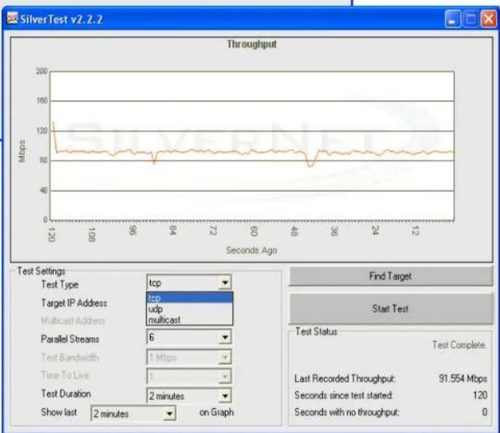
line
| Seconds Ago | Throughput (Mbps) | | ----------- | ----------------- | | 120 | 120 | | 108 | ~85 | | 96 | ~85 | | 84 | ~85 | | 72 | ~85 | | 60 | ~85 | | 48 | ~85 | | 36 | ~85 | | 24 | ~85 | | 12 | ~85 |Need Help?
Defaults:
Wireless SSID silvernetwireless
Wireless Encryption key: silvernetwireless
Wireless Encryption type: AES
IP Address of Device 1 : 192.168.0.228
IP Address of Device 2 : 192.168.0.229
Subnet Mask of Devices : 255.255.255.0
Admin Username : admin
Admin Password : password
If you need any further assistance go to our website download centre:
www.silvernet.com/downloadcentre/
- Read the easy as 1-2-3 setup guide
- View our troubleshooting guide: www.silvernet.com/support/FAQ.php
- Read the Manual: www.silvernet.com/downloadcentre/Userguides/11n-Manual.pdf
- use our online ticket support: www.silvernet.com/support/
- email us at support@silvernet.com
- call our support team on 08712233067
Note:
More information and SilverView NMS please go to our website download centre:
www.silvernet.com/downloadcentre/
Contact Us

0800 652 1629

sales@silvernet.com

www.silvernet.com
- Wireless Application Setups
- PRO RANGE
- Point To Point Advantages
- PRO RANGE – 95Mbps
- PICO-1KM
- MICRO-2KM
- LTE-6KM
- MAX-60KM
- PRO RANGE - 240Mbps
- MICRO 240 - 2KM
- LITE 240-6KM
- MAX 240 - 60KM
- PRO RANGE - 500Mbps
- LITE 500 - 6KM
- MAX 500 - 60KM
- PRO RANGE – 1000Mbps
- Point to Point System Antenna Beamwidths
- Antenna Alignment is Important
- Point to Point Wireless Link for a Network
- Point to Point wireless Link Single analogue camera via ip encoder and decoder
- Note for IP cameras :
- Point to Point Wireless Link Multiple analogue cameras via IP encoder and decoder
- Point to Point Wireless Link with Multiple IP cameras
- Point to point Wireless Link Repeater for a Network
- Point to Point wireless link Repeater Single analogue camera via IP encoder and decoder
- SilverNet Hardware
- Ordering a Point to Point Link
- PURCHASE SILVERNET PRODUCTS VIA OUR DISTRIBUTION AGENTS
- Point To Multipoint Advantages
- PRO RANGE – 500Mbps
- BASE 500 90 - 2KM
- BASE 500 360 - 1KM
- BASE 500 - MP
- BASE 500 Optional Antenna
- BASE 500 Antenna Beamwidth and Range
- Multipoint System Omni Antenna
- Point to Multipoint Wireless Link For a Network
- Point to Multipoint wireless Link Multiple analogue cameras via ip encoder and decoder
- What's in the box?
- - BASE 500 90
- BASE 500 360
- BASE 500
- Options
- Ordering a Point to Multipoint AP/BASE
- BASE 500 options:
- Ordering a Point to Multipoint CLIENT
- Monitoring Software
- Download for FREE from our website Download Centre
- SilverView
- Makes easy, even easier!
- ■ Real Time Monitoring
- ■ Built in Data tester
- Need Help?
- Contact Us
Brand : SilverNet
Model : SIL 4.9 MICRO 95-PCP
Category : Wi-Fi Router