Micro 95 - Wi-Fi repeater SilverNet - Free user manual and instructions
Find the device manual for free Micro 95 SilverNet in PDF.


| Product Type | Wi-Fi Repeater |
| Brand | SilverNet |
| Model | Micro 95 |
| Frequency Band | 2.4 GHz |
| Wireless Standards | IEEE 802.11 b/g/n |
| Maximum Speed | 300 Mbps |
| Dimensions (L x W x H) | 70 x 50 x 30 mm |
| Weight | 50 g |
| Power Supply | AC 100-240V, 50/60Hz, built-in plug |
| Power Consumption | 5 W (max) |
| Buttons | WPS, Reset |
| LED Indicators | Power, WLAN, LAN (if available) |
| Antenna Type | Internal |
| Security | WPA/WPA2-PSK, WEP |
| Operation Modes | Repeater, Access Point |
| Installation | Plug and play via WPS or web interface |
| Operating Temperature | 0°C to 40°C |
| Humidity | 10% to 90% non-condensing |
| Cleaning | Wipe with a soft, dry cloth |
| Repairability | Not user-serviceable; contact SilverNet support |
Frequently Asked Questions - Micro 95 SilverNet
User questions about Micro 95 SilverNet
0 question about this device. Answer the ones you know or ask your own.
Ask a new question about this device
Download the instructions for your Wi-Fi repeater in PDF format for free! Find your manual Micro 95 - SilverNet and take your electronic device back in hand. On this page are published all the documents necessary for the use of your device. Micro 95 by SilverNet.
USER MANUAL Micro 95 SilverNet
WIRELESS-NETWORK-SOLUTIONS
PRO RANGE 95
natural_image
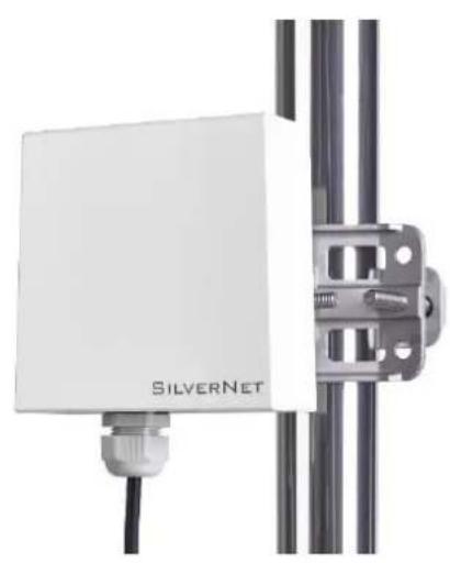
Exterior view of a SilverNet sensor device mounted on a vertical metal frame (no text or symbols visible beyond the brand name)PICO 95
natural_image
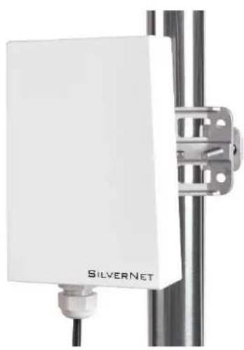
White SilverNet sensor mounted on a metal frame (no visible text or symbols beyond brand name)MICRO 95
natural_image
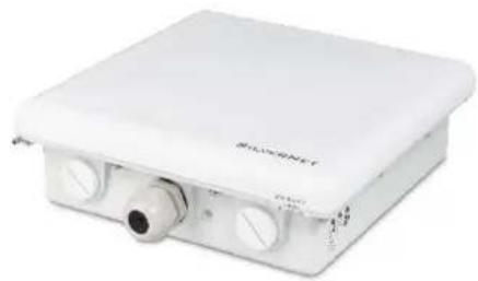
White electronic device with ports and a cylindrical connector (no visible text or symbols)LITE 95
natural_image
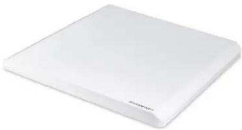
White rectangular electronic device with rounded edges and a small logo on the front face (no visible text or symbols on body)MAX 95
User Manual
TABLE OF CONTENTS
Introduction......4
Supported Products.... 4
Wireless Modes 4
System Requirements.... 4
Packing list....5
The Enclosure and LED indicators 6
Configuration....7
Getting Started 7
Navigation....8
Status Tab 9
Overview.... 10
Realtime Graphs 12
Admin Tab.... 13
System 13
Administration.... 15
SNMP 16
SNMP Trap.... 17
LED Configuration.... 18
Backup/Flash Firmware.... 19
Services Tab 20
Ping Watchdog....20
Auto Reboot 20
Dynamic DNS 21
Network Tab 21
LAN Interface 23
DHCP Server 25
Static Leases 26
Wireless Interface.... 28
Spectrum scans.... 28
Configuration pages.... 29
Device Configuration 30
Advanced settings 33
Wireless Security 37
WEP 38
WPA/WPA2 Authentication.... 38
MAC-Filter 39
Advanced Settings 39
VLANS 41
VLAN Activation.... 41
VLAN Entries 41
VLAN Management Setup 42
Standards.... 43
Declaration of Conformity 43
Warnings....44
Radio frequency Interference Requirements.... 44
Troubleshooting 46
Warranty....46
Contact SilverNet.... 46
Copyright Information....46
Other SilverNet Products.... 47
Pro Range 47
Industrial Network Transmission.... 47
Intelligent Wi-Fi Solutions 47
Industry Leading Technical Support 47
INTRODUCTION
This User Guide describes the firmware version 2.42.25 which is integrated into all Pro Range 95 products provided by SilverNet Ltd.
SUPPORTED PRODUCTS
This manual covers all Pro 95 products listed below:
- PICO 95
- MICRO 95
• LITE 95
• MAX 95
For more information, visit www.silvernet.com
WIRELESS MODES
The Pro Range supports the following wireless modes:
- Station
- Station WDS
- Access Point
- Access Point WDS
SYSTEM REQUIREMENTS
- Windows XP, Windows Vista, Windows 7, Windows 8, Windows 10, Linux, or Mac OS X
- Web Browser: Mozilla Firefox, Apple Safari, Google Chrome, or Microsoft Internet Explorer 9 (or above)
PACKING LIST
Please check the following items in the package before installing the device
Wireless Radio 1 piece
User manual 1 copy
Cable Gland 1 piece
Mounting bracket 1 piece
Power over Ethernet Injector 1 piece
Power cable 1 piece
Set of screws 1 piece
Please contact your distributor immediately for any missing or damaged items.
THE ENCLOSURE AND LED INDICATORS
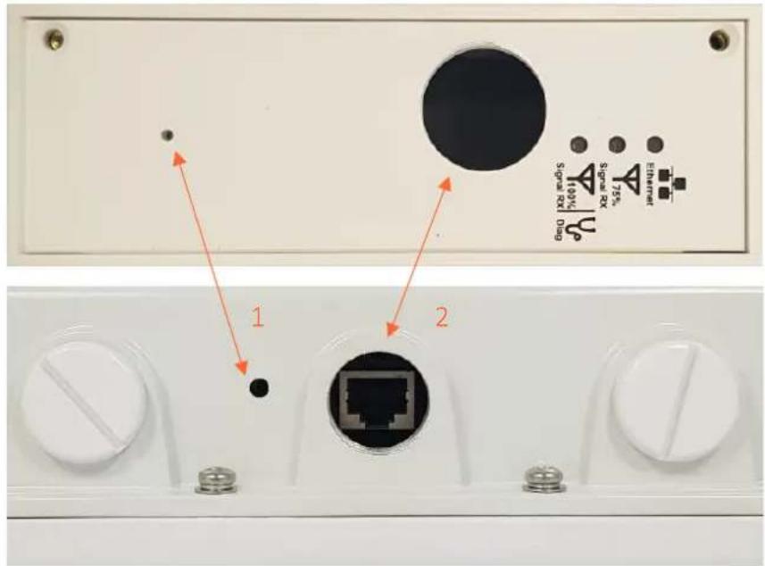
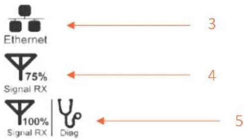
flowchart
graph TD
    A["Ethernet"] -->|3| B["Diag"]
    C["Signal RX 75%"] -->|4| D["Diag"]
    E["Signal RX 100%"] -->|5| F["Diag"]
| Mark | Name | Function |
| 1 | Reset Button | Press to reboot the device manuallyHold to rest the device to factory settings |
| 2 | Ethernet Port (PoE) | 10/100Mbps Ethernet port and PoE power input (48V DC) |
| 3 | Ethernet link LED | "On/Blinking": Power is being supplied and a link has been established to the network."Off": No power and/or the Ethernet port has no connection |
| 4 | 75% Signal Rx LED | "On": Signal Strength is at 75%"Off": Signal Strength not at 75% |
| 5 | 100% Signal Rx LED | "On": Signal Strength is at 100%"Off": Signal Strength not at 100%"Blinking": Device is in diagnostic mode |
CONFIGURATION
GETTING STARTED
To access the Pro Range Configuration Interface, perform the following steps:
- Configure the Ethernet adapter on your computer with a static IP address on the 192.168.0.x subnet (for example, IP address: 192.168.0.100 and subnet mask: 255.255.255.0
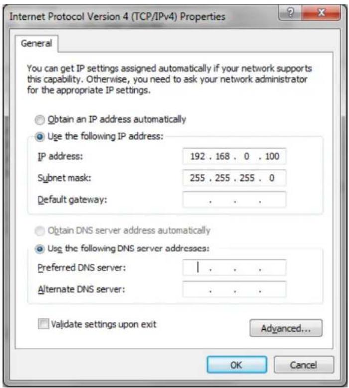
- Launch your web browser and enter the default IP address of your device in the address field.
Pro Range products are pre-configured to IP address 192.168.0.229/192.168.0.228
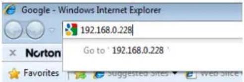
If the unit has been reset, it will go to the default IP address of 192.168.1.1. You will need to change your Ethernet adapter IP address to 192.168.1.x subnet.
- Enter admin in the Username field and password in the Password field and click Login.
NAVIGATION
The Pro Range Configuration Interface contains four main tabs, each with sub tabs which provide a web-based management page to configure a specific aspect of the SilverNet device:
Status Admin Services Network Logout
- Status The "Status Tab" displays device status, system logs, and real-time graphs.
- Admin The "Admin Tab" displays basic system properties, administration, SNMP configuration, LED Configuration, file and firmware management and Reboot.
- Services The "Services Tab" allows you to configure services such as Ping Watchdog, Dynamic DNS and Auto Reboot.
- Network The “Network Tab” configures the network operating mode; This includes LAN Interface settings, Wireless Settings and VLAN Management.
- Logout The "Logout Tab" allows you to logout of the unit.
Apply Settings To apply any settings to the radio, click Save and Apply
STATUS TAB
The Status tab displays a summary of the link status information, current values of the basic configuration settings (depending on the operating mode), network settings and information, and traffic statistics.
![SILVERNET HEDNES 13:42:25 (1000001) | auto.Radish. com Status: Access Services Network Link-up Overview: Software Engine Status Wireless 5GHz Radio MAC Address Mode: Home-4600 Channel: 112 (3,000 MHz) Diluted: 100 MHz MACD: 50 (11,880,000 MHz) Network Name: MACD (IPAC) (IPAC/ANOS) ASK Status: (S) BPS Status: C:\Users\* Annotated Stations [1] MAC Address Network Device Name Last IP Signal Signal/Chains Noise TX Rate RX Rate TX-COQ no information available System Unit Name MACD Unit Model MAC D Pressure Version 10.42 (25.33920145) Kernel Version 3.5.6 Local Free Date Feb 18 17-08-31 2009 Memory Total Available 31045.48 / 6,422.48 (30%) Free 31045.48 / 6,422.48 (30%) Network Network Status Address: 24 218 230 24x MAC Address: 30111188.00/95/27 Protocol: (PAC) RG: 22.12 NO (074793 PktL) TE: 27.04.19B (196303 PktL) EPA: 192.598.268.81/14 ethls.csc ethls.bccm](/content/2026/05/971526/images/e89f1fd0ab365c546f4ae1868e4c434c6c4be81225f793481756d34486b11edb.jpg)
AP status page
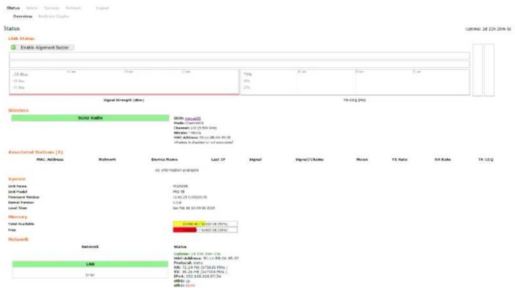
Station status page
The alignment buzzer is only available on the station end of the link
The max number of beeps is 4; this means you have a good link.
OVERVIEW
Wireless This shows you the SSID, operating mode, channel frequency, bitrate, BSSID, encryption status, the ACK (acknowledgment timeout) and the DFS status.
In station mode you will also see TX CCQ, RX Rate and TX Rate.
Associated Stations Displays the MAC address, SSID and signal information of any stations connected to the AP.
System Displays the name of the device, the firmware version and the current system date and time. The date and time are displayed in DAY-MONTH-YEAR HOURS:MINUTES:SECONDS format.
Memory Displays the total amount of memory on the board and shows how much is free in kB (Kilobytes).
Network Displays local device information including the current uptime, MAC address and IP address.
Wireless parameters
SSID Displays the name of the wireless network that the AP is transmitting, the Service Set Identifier (SSID), is what you will see if you scan with your laptop.
Mode This is "Master" if the device is set in AP mode or AP WDS Mode.
This will show as "client" if the device is in station mode or station WDS mode.
Channel Shows the channel number and frequency that the device is using.
Bitrate This is the maximum bitrate supported by the radio.
BSSID Displays the MAC address of the device.
Encryption Displays the wireless encryption used.
ACK Timeout shows the maximum acknowledgment time in microseconds.
DFS Status If DFS is enabled, the device will automatically switch channels if any radar is detected on the current channel it is using.
Associated stations parameters
MAC Address Displays the MAC address of the device
Network States the name of the wireless network
Device Name Shows the name of the device
Last IP Shows the most recent IP address of the associated device as seen by the router
Signal Displays the received signal strength
Signal Chains Shows the received signal strengths of each antenna e.g. -52, -49, -51 dBm. If the device only has 2 antennas you may see one value as -95 dBm.
Noise Displays the received noise power at the AP
TX Rate shows the transmit bitrate of the device.
RX Rate shows the receive bitrate of the device.
TX CCQ Displays the transmission quality in %. A higher percentage means better wireless connection quality.
REALTIME GRAPHS
There are four different graphs, you can view Load, Traffic, Wireless and connection graphs.
Realtime Load
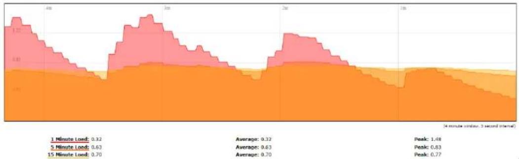
area
| Timeframe | Load Value | | :--- | :--- | | 1 Minute Load | 0.32 | | 5 Minute Load | 0.63 | | 15 Minute Load | 0.70 | | Peak | 1.48 | | Average | 0.32 | | Average | 0.63 | | Average | 0.70 | | Peak | 0.83 | | Peak | 0.77 | (4 minute window, 3 second interval)Realtime Traffic
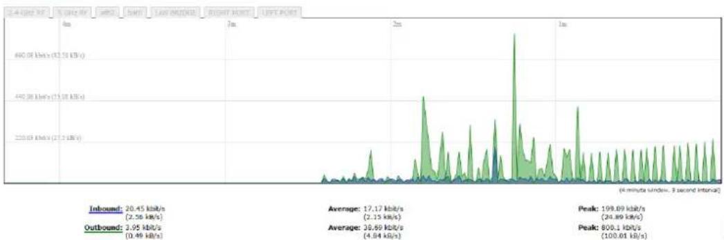
line
| Metric | Value | | -------------- | ----------- | | Inbound | 20.45 kbits/s | | Average | 17.17 kbits/s | | Peak | 198.09 kbits/s | | Outbound | 26.69 kbits/s | | Peak | 800.1 kbits/s |Realtime Wireless
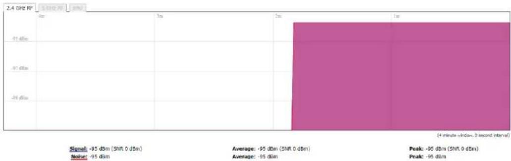
bar
| Signal | -95 dBm (SNR, 0 dBm) | Average | -95 dBm (SNR, 0 dBm) | Peak | -95 dBm (SNR, 0 dBm) | Peak | | :--- | :--- | :--- | :--- | :--- | :--- | :--- | | Noise | -95 dBm | -95 dBm | -95 dBm | -95 dBm | -95 dBm | -95 dBm | (4 minute window, 3 second interval)Realtime Connections
This page gives an overview over currently active network connections.
Active Connections
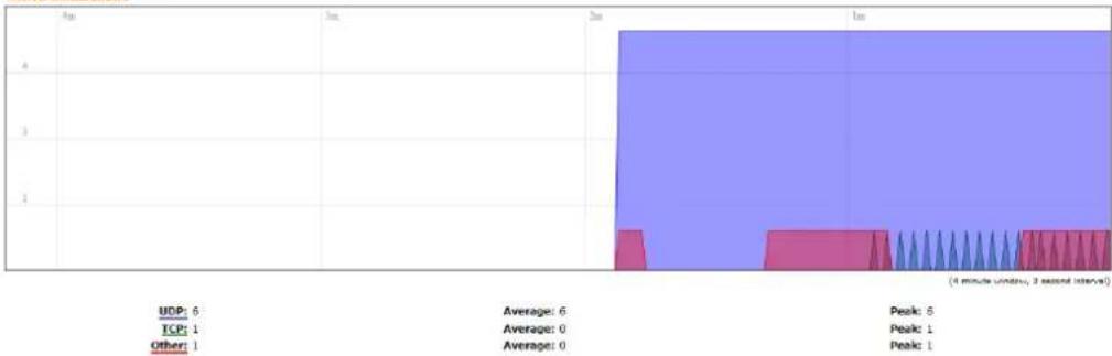
bar
| Category | Value | |---|---| | UDP | 6 | | TCP | 1 | | Other | 1 | | Average | 6 | | Peak | 6 | | Average | 0 | | Average | 0 | | Peak | 1 | | Peak | 1 | (4 minute London, 2 second interval)ADMIN TAB
The Admin tab contains administrative options. This page enables the administrator to configure System Properties, Time Synchronisation, Logging Settings, User Management, Web Administration, SNMP Configuration, LED Configuration, Backup config files / flash new firmware and reboot the device.
SYSTEM
| Status | Admin | Services | Network | Logout | ||
| System | Administration | SNMP | LED Configuration | Backup / Flash Firmware | Reboot | |
System
Here you can configure the basic aspects of your device like its hostname or the timezone.
System Properties

Time Synchronisation

Reset Save Save & Apply
General Settings
Local Time Displays the local time according to the time zone
Host Name Enter a name for your device
Time Zone Select the correct time zone from the drop-down menu
Time Synchronisation
Enable NTP Client Check to enable NTP
NTP Server Enter your preferred time server
NTP Server Candidates These are the sources where you get your time information. We recommend you enter at least three for accurate time synchronisation.
| Status | Admin | Services | Network | Logout | ||
| System | Administration | SNMP | LED Configuration | Backup / Flash Firmware | Reboot |
System
Here you can configure the basic aspects of your device like its hostname or the timezone.
System Properties
| General Settings | Logging |
| System log buffer size | 16 |
| kΩ | |
| External system log server | 0.0.0.0 |
| External system log server port | 514 |
| Log output level | Debug |
| Cron Log Level | Normal |
Logging
System Log Buffer Size Change the size of the log buffer
External System Log Server Input an address that the system log is sent to
External System Log Server Port Input an external server port.
Log Output Level Change the type of log report
Cron Log Level Change the level of log report
ADMINISTRATION
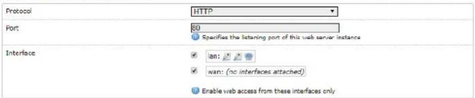
Use this section to change the administrator password and the port you use to access the device. Default is port 80.
Radio Password

Radio Password
Changes the administrator password for accessing the device

Web
Provides administrator tools to control the device
Reset Save Save & Apply
Password Enter a new password
Confirmation Re-enter your new password
Web
Protocol Pick from HTTP and HTTPS.
Port Specify the listening port of the Web server.
Interface You can choose to only enable web access from the ticked interfaces. This is very useful when using a management VLAN.
SNMP
Simple Network Management Protocol (SNMP) is a popular protocol for network management. It is used for collecting information from, and configuring, network devices on an IP network.
| Status | Admin | Services | Network | Logout | ||
| System | Administration | SNMP | LED Configuration | Backup / Flash Firmware | Reboot | |
SNMP
Here you can configure your SNMP V2c and SNMP V3,read and write password
SNMP Information
| Information | |
| Contact | Test |
| Location | Test |
SNMP Configuration
| General Settings | Trap |
| Enable SNMP | |
| SNMP V2c Read Password | public |
| SNMP V2c Write Password | private |
| SNMP V3 Username | admin |
| SNMP V3 Auth Algorithm | MD5 |
| SNMP V3 Auth Password | ********** |
| SNMP V3 Privacy Algorithm | DES |
| SNMP V3 Privacy Password | ********** |
Reset Save Save & Apply
SNMP Information
These identifiers are arbitrary and do not affect the server's function, but they are useful to have. The contact is the person who manages the server. The location is the server's physical location. Each of these parameters can be up to 64 characters.
Contact Enter the name of the person who manages the server.
Location Enter the server's physical location
SNMP Configuration
Enable SNMP Enable SNMP
SNMP V2c Read Password Sets the community string for read-only access (to the carriables on the SNMP agent) by the Network Management Station (NMS). The NMS is the software that runs on the SNMP manager. (default: public)
SNMP V2c Write Password Sets the community string for read-write access by the SNMP manager. (default: private) A community string identifies a group of SNMP agents. It is sent in clear text. It should be changed from the default string "public" or "private". The variables on the SNMP agent can be classified into read-only or read-write variables.
SNMP V3 Username Sets the username for authentication. (default: admin)
SNMP V3 Auth Algorithm Shows the authentication algorithm used e.g. MD5.
SNMP V3 Auth Password Configures the password for user authentication. (default: password)
SNMP V3 Privacy Algorithm Shows the data encryption algorithm used e.g. DES.
SNMP V3 Privacy Password Sets the password for data encryption. (default: password)
SNMP Configuration

SNMP TRAP
Enable SNMP Trap Allows the SNMP agent to notify the SNMP manager of events.
SNMP Trap IP Address Sets the IP address of the SNMP manager which receives the trap messages.
SNMP Trap Port Sets the port number.
LED CONFIGURATION
You can configure the LEDs on the device to light up when received signal levels reach the values defined in the four fields.
LED Configuration
Customizes the behaviour of the device LEDs.
Signal strength indicator interface
| Wireless interface | Master-WDS "silvernetwireless1" (ath1) |
| Signal strength indicator LEDs | |
| LED#1 | -85 |
| LED#2 | -75 |
| LED#3 | -65 |
| LED#4 | -55 |
Signal Strength Indicator Interface Choose the wireless interface (wireless network name) to display LEDs for.
Signal Strength Indicator LEDs Sets the received signal strength thresholds (in dBm), if the signal is above the threshold, the LED will light up.
BACKUP/FLASH FIRMWARE
| Status | Admin | Services | Network | Logout | ||
| System | Administration | SNMP | LED Configuration | Backup / Flash Firmware | Reboot |
Flash operations
Actions
Backup / Restore
Click "Generate archive" to download a tar archive of the current configuration files. To reset the firmware to its initial state, click "Perform reset".
Download backup:
Generate archive
Reset to defaults:
Perform reset
To restore configuration files, you can upload a previously generated backup archive here.
Restore backup:
Choose file No file chosen
Upload archive.
Flash new firmware
Upload a firmware here to replace the running firmware. Check "Keep settings" to retain the current configuration.
Keep settings:
√
Firmware: (current ver: v2.42.22 (17072018))
Choose file No file chosen
Flash firmware.
Backup / Restore
Download Backup Click to save down the configuration file of the device.
Reset to Defaults This will reset the device to the default factory settings (IP address 192.168.1.1)
Restore Backup Select the configuration file you wish to upload and click the restore button.
Flash new firmware
Keep Settings Enable to keep the current settings after firmware upgrade.
Choose File Select the firmware file you wish to upgrade and click upload to begin the update process.
Please be patient, as the firmware upgrade routine can take 5-10 minutes. The device will be un-accessible until the firmware upgrade is completed.
Do not switch off the device! Do not reboot and do not disconnect the device from the power supply during the firmware upgrade process as these actions will damage the device!
Reboot
Perform Reboot This option will perform a reboot of your device.
SERVICES TAB
The Services tab provides useful and enhanced functions to help assist device operations.
Status Admin Services Network Logout
Ping Watchdog Dynamic DNS
Ping Watchdog and Auto Reboot
Configure Ping Watchdog and Auto Reboot Service
Ping Watchdog
| Enable Ping Watchdog | |
| IP Address to Ping | 192.168.1.1 |
| Ping Interval | 5 |
| Startup Delay | 60 |
| Failure Count to Reboot | 5 |
Auto Reboot
| Enable Auto Reboot | |
| Mode | By Time▼ |
| Time (HH:MM 24 Hours) | 12:41 |
Reset Save Save & Apply
PING WATCHDOG
Enable Ping Watchdog Default is disabled. Check the box to enable. This mode lets you choose a network device to ping. If the device does not receive a ping response as per the settings, it will perform a reboot.
IP Address to Ping Target IP address to ping
Ping Interval Default is 5 seconds (minimum). This is Ping test duration.
Startup Delay Default is 60 seconds (minimum). One-time delay after device "start-up" procedure
Failure Count to Reboot Default is 5. This is the number of ping failure counts before the device begins the reboot process.
AUTO REBOOT
Enable Auto Reboot Default is disabled. Check the box to enable. This mode lets you pre-set a timer to automatically force a reboot. Timer can in fixed number of hours or at a specified time of day.
Mode Select by Number of Hours or By Time
By Time Enter the specific time of day in hh:mm (24-hour format) to start the reboot process.
DYNAMIC DNS
Dynamic DNS (DDNS) allows the device to be reached from the internet via a URL by translating a URL like www.silvernet.com to an IP address like 206.190.36.45

Dynamic DNS
Dynamic DNS allows that your router can be reached with a fixed hostname while having a dynamically changing IP address.
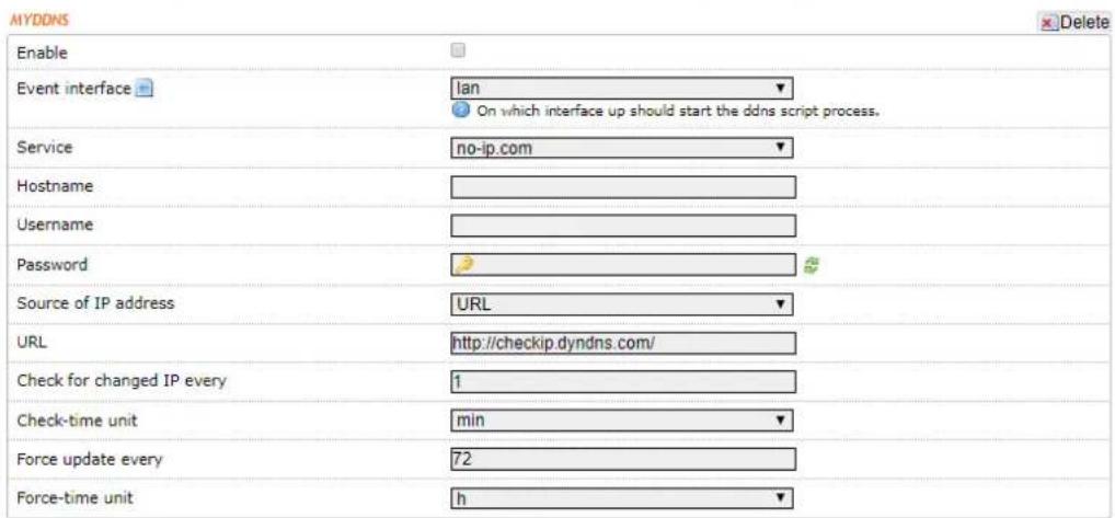
Enable Enables the dynamic DNS.
Event Interface Chooses the interface, e.g. LAN or WAN, to run the DDNS script process.
Service Chooses the DDNS service provider e.g. no-ip.com.
Hostname Specifies the hostname e.g. y0033.no-ip.biz.
Username Sets the username registered for the DDNS service.
Password Sets the password registered for the DDNS service.
Source of IP Address Configures the source of the IP address information. The default is URL.
URL Set the URL of the source of the IP address information, e.g. http://checkip.dyndns.com
Check for changed IP Every The default is to check the IP address every 1 minute.
Check-Time Unit Select Minutes (min) or hours (h) from the dropdown menu.
Force Update Every The default is to force an update every 72 hours.
Force-Time Unit Select Minutes (min) or hours (h) from the dropdown menu.
NETWORK TAB
The Network tab contains everything needed to set up the wireless part of the link. This includes:
- LAN Interface: This allows you to configure the IP Address settings, DHCP Server Settings, Static Leases and STP settings.
- Wireless Settings: This allows you to configure settings such as Country Codes, Channel Selection, ACS Scanning, Antenna Gain, Transmit Power, Interface Configuration, Wireless Security, MAC-filtering, Multipoint Enhancement Settings, Distance Settings, Adaptive Noise Immunity, Chainmask Selection, Dynamic Channel Selection.
• VLANs: This allows you to enable and manage VLANs to your specifications.

Interfaces
Interface Overview
Network
Status
Uptime: 2h 26m 2s
MAC-Address: 50:11:EB:00:74:A3
Protocol: static
RX: 7.78 MB (64881 Pkts.)
TX: 7.20 MB (33149 Pkts.)
IPv4: 192.168.168.70/24
Actions

Note Click the edit button to enter the set-up page for LAN or WAN interface
LAN INTERFACE
Status Admin Services Network Logout
Interfaces
Wireless
VLANs
LAN
Interfaces - LAN
Common Configuration
| General Setup Advanced Settings Physical Settings | |
| Status Uptime: 2h 26m 48sMAC-Address: 50:11:EB:00:74:A3RX: 7.80 MB (65117 Pkts.)TX: 7.23 MB (33266 Pkts.)IPv4: 192.168.168.70/24 | |
| Protocol Static address | |
| IPv4 address 192.168.168.70 | |
| IPv4 netmask 255.255.255.0 | |
| IPv4 gateway | |
| IPv4 broadcast | |
| Use custom DNS servers | |
| Accept router advertisements | |
| Send router solicitations | |
| IPv6 address | |
| IPv6 gateway | |
DHCP Server
General Setup
Ignore interface

Disable DHCP for this interface.
Static Leases
Static leases are used to assign fixed IP addresses and symbolic hostnames to DHCP clients. They are also required for non-dynamic interface configurations where only hosts with a corresponding lease are served. Use the Add Button to add a new lease entry. The MAC-Address identifies the host, the IPv4-Address specifies to the fixed address to use and the Hostname is assigned as symbolic name to the requesting host.
Hostname
MAC-Address
IPv4-Address
This section contains no values yet


Reset
Save

ve & Apply
Common Configuration
General Setup
Protocol Here you can enable DHCP Client or Static (default)
DHCP Client If enabled, your device will get an IP address automatically from the network. There must be a DHCP server on your network for this to work.
Static Allows you to enter a static IP address.
IPv4 Address Enter the IP address you wish to give to the device. You will use this IP address to access the device interface.
IPv4 Netmask Enter the class for the IP address. The default is a class C value of 255.255.255.0
IPv4 Gateway (optional) Enter the gateway IP address of the network the device is connected to.
IPv4 Broadcast (optional) Specifies the IPv4 broadcast address
Use Custom DNS Servers Enter the IP address for the DNS server you wish to use
Accept Router Advertisements Check to enable
Send Router Solicitations Check to enable
IPv6 Address (optional) Enter the IPv6 address you wish to give to the device. You will use this IP address to access the device interface.
IPv6 Gateway (optional) Enter the gateway IPv6 address of the network the device is connected to.
DHCP SERVER
DHCP Server disabled if ticked, un-tick to enable.
DHCP Server
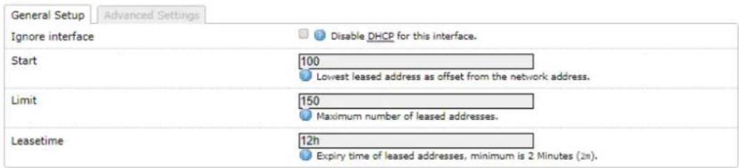
DHCP Server
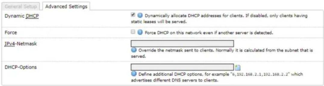
DHCP Server The device will act as a DHCP server hand out IP addresses automatically.
Start Specifies the lowest leased address to be issued
Limit Sets the maximum number of leased addresses
Leasetime States the expiry time of leased addresses
Dynamic DHCP Dynamically allocates DHCP addresses for clients. If disabled, only clients having static leases will be served.
Force Forces DHCP on this network even if another server is detected
IPv4 Netmask Overrides the netmask sent to clients. Normally it is calculated from the subnet that is served.
DHCP Options Defines additional DHCP options, for example "6, 192.168.2.1, 192.168.2.2" which advertises different DNS servers to clients. Normally, connected devices would take this board's IP address as the default gateway. To set an alternative default gateway, add the DHCP option "3, 192.168.2.3" for example.
STATIC LEASES
Static Leases
Hostname
MAC-Address
IPv4-Address
Add
This section contains no values yet
Static Leases Static leases are used to assign fixed IP addresses and symbolic hostnames to DHCP clients. They are also required for non-dynamic interface configurations where only hosts with a corresponding lease are served.
Use the Add Button to add a new lease entry. The MAC-Address identifies the host, the IPv4-Address specifies to the fixed address to use and the Hostname is assigned as symbolic name to the requesting host.
Advanced Settings
Interfaces - LAN
Common Configuration

Override MAC Address Allows you to specify a different MAC address other than the routers original one. This is useful if the ISP uses Mac addresses of routers to identify customers.
Override MTU Sets the maximum transmission unit (MTU), the default being 1500 bytes, we recommend you do not change this unless your ISP requires you to.
Use Gateway Metric Allows you to specify a gateway metric. When a connected device must choose from multiple gateways, the gateway with the smallest/lowest metric is chosen.
Physical Settings
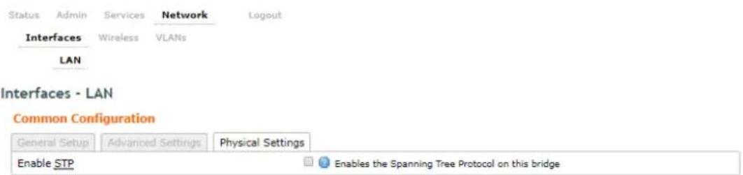
Enable STP Enables the Spanning Tree Protocol on this unit. This is disabled by default
The Spanning Tree Protocol (STP) is a network protocol. The main purpose of STP is to ensure that you do not create loops when you have redundant paths in your network. Loops are deadly to a network.
WIRELESS INTERFACE
Status Admin Services Network Logout
Interfaces Wireless VLANs
wifi0: Master-WDS "silvemetwireless"
Wireless Overview

Associated Stations
| MAC-Address | Network | Signal | Signal/Chains | Noise | TX Rate | RX Rate | TX-CCQ |
| 50:11:EB:00:72:6D | silvernetwireless | -50 dBm | -55,-56,-95 dBm | -95 dBm | 269.8 Mbit/s | 270.1 Mbit/s | 95 % |
SPECTRUM SCANS
Click the Spectrum button to perform a spectrum scan from the AP
| The number of channels scanned for acs report is: 25 Channel | # Access Points | Min RSSI | Max RSSI | |||||
| 5180(36) | 2 | -95 dBm | -95 dBm | -117 dBm | 1% |
| 5200(40) | 1 | -94 dBm | -94 dBm | -117 dBm | 16% |
| 5220(44) | 2 | -83 dBm | -82 dBm | -117 dBm | 1% |
| 5240(48) | 0 | -95 dBm | -95 dBm | -116 dBm | 0% |
| 5260(52) | 0 | -95 dBm | -95 dBm | -115 dBm | 0% |
| 5280(56) | 0 | -95 dBm | -95 dBm | -115 dBm | 0% |
| 5300(60) | 2 | -72 dBm | -72 dBm | -114 dBm | 1% |
| 5320(64) | 0 | -95 dBm | -95 dBm | -114 dBm | 0% |
| 5500(100) | 2 | -82 dBm | -81 dBm | -112 dBm | 1% |
| 5520(104) | 0 | -95 dBm | -95 dBm | -113 dBm | 0% |
| 5540(108) | 1 | -70 dBm | -70 dBm | -113 dBm | 1% |
| 5560(112) | 0 | -95 dBm | -95 dBm | -113 dBm | 1% |
| 5580(116) | 2 | -43 dBm | -43 dBm | -113 dBm | 1% |
| 5600(120) | 0 | -95 dBm | -95 dBm | -112 dBm | 1% |
| 5620(124) | 0 | -95 dBm | -95 dBm | -113 dBm | 1% |
| 5640(128) | 0 | -95 dBm | -95 dBm | -113 dBm | 1% |
| 5660(132) | 0 | -95 dBm | -95 dBm | -113 dBm | 1% |
| 5680(136) | 1 | -31 dBm | -31 dBm | -112 dBm | 1% |
| 5700(140) | 0 | -95 dBm | -95 dBm | -114 dBm | 1% |
| 5720(144) | 0 | -95 dBm | -95 dBm | -114 dBm | 1% |
| 5745(149) | 1 | -36 dBm | -36 dBm | -115 dBm | 1% |
| 5765(153) | 0 | -95 dBm | -95 dBm | -116 dBm | 1% |
| 5785(157) | 1 | -79 dBm | -79 dBm | -116 dBm | 12% |
| 5805(161) | 1 | -63 dBm | -63 dBm | -117 dBm | 1% |
| 5825(165) | 0 | -95 dBm | -95 dBm | -117 dBm | 1% |
This will show you a list detailing the channel number, how many other access points are on that channel and the power/interference levels on those channels.
Wireless Overview

Click the Scan button to perform a spectrum scan from the Station
Status Admin Services Network Logout
Interfaces Wireless VLANs
Join Network: Wireless Scan
| SilverNet1 Channel: 140 | Mode: Master | BSSID: 50:11:EB:10:13:B0 | Encryption: open | Join Network |
| SilverNet1 Channel: 60 | Mode: Master | BSSID: 50:11:EB:10:17:28 | Encryption: open | Join Network |
| silvernetwireless888 Channel: 149 | Mode: Master | BSSID: 50:11:EB:00:6F:62 | Encryption: WPA2 - PSK | Join Network |
| silvernetwireless Channel: 36 | Mode: Master | BSSID: 50:11:EB:00:74:A5 | Encryption: WPA2 - PSK | Join Network |
| silvernetwireless4321 Channel: 161 | Mode: Master | BSSID: 50:11:EB:00:6E:6E | Encryption: WPA2 - PSK | Join Network |
| SilverNet Channel: 116 | Mode: Master | BSSID: 14:1F:BA:7D:80:84 | Encryption: WPA2 - PSK | Join Network |
This will show you a list detailing the channel number, MAC address and encryption method of any devise nearby. You can click the "Join Network" button to connect to a specific AP.
CONFIGURATION PAGES
From the Wireless Overview page, click the edit button to enter the wireless page
Wireless Overview

Associated Stations
| MAC-Address | Network | Signal | Signal/Chains | Noise | TX Rate | RX Rate | TX-CCQ |
| 50:11:EB:00:72:6D | silvernetwireless | -50 dBm | -55,-56,-95 dBm | -95 dBm | 269.8 Mbit/s | 270.1 Mbit/s | 95 % |
DEVICE CONFIGURATION
Device Configuration
| General Setup Advanced Settings | |
| Status | Mode: Master-WDS | SSID: silvernetwireless BSSID: 50:11:EB:00:74:A5 | Encryption: WPA2 PSK (AUTO) Channel: 36 (5.180 GHz) | Tx-Power: 23 dBm Signal: -53 dBm | Noise: -95 dBm Bitrate: 300.0 Mbit/s | Country: No Country |
| Wireless network is enabled | Disable |
| Country Code | No Country |
| Wireless Profile | 802.11a+n |
| Channel Spectrum Width | 40MHz 2nd channel above |
| Channel | Auto |
| Background ACS scan | Automatically scan and switch to best channel after a period of time when no client is connected. |
| Channels To Block From Channel Scan: | Enable Scan List 36 (5.180 GHz) 40 (5.200 GHz) 44 (5.220 GHz) 48 (5.240 GHz) 52 (5.260 GHz) 56 (5.280 GHz) 60 (5.300 GHz) 64 (5.320 GHz) 100 (5.500 GHz) 104 (5.520 GHz) 108 (5.540 GHz) 112 (5.560 GHz) 116 (5.580 GHz) 120 (5.600 GHz) 124 (5.620 GHz) 128 (5.640 GHz) 132 (5.660 GHz) 136 (5.680 GHz) 140 (5.700 GHz) 144 (5.720 GHz) 149 (5.745 GHz) 153 (5.765 GHz) 157 (5.785 GHz) 161 (5.805 GHz) 165 (5.825 GHz) When enabled, each ticked channel will be ignored during the Channel Scan |
| Antenna Gain (dBi) | 0 |
| Transmit Power | Full Max EIRP: 30 |
| Outdoor Channels | Only applicable to European countries |
Status This shows the current wireless connectivity of the device, similar to the "Status Tab".
Country Code Each country has their own power level and frequency regulations. To ensure the device operates under the necessary regulatory compliance rules, you must select the country where your device will be used. The IEEE 802.11 mode, channel and frequency settings, and output power limits will be tuned according to the regulations of the selected country.
Wireless Profile Select to use 802.11ac or 802.11n. The choice of 802.11n is a combination of 802.11a and 802.11n and operates in the 5 GHz frequency band. The 802.11ac is the latest standard that offers even higher data rates and it also operates in the 5 GHz frequency band.
Channel Spectrum Width Displays the spectral width of the radio channel. You can use this option to control the bandwidth consumed by your link. Using higher Channel width increases throughput. Using lower Channel width reduces throughput.
Channel widths available are 5 MHz, 10 MHz, 20 MHz, and 40 MHz
When the 802.11ac wireless standard is used, the 80 MHz band can be selected. An 80 MHz band can carry twice the amount of data of a 40 MHz band.
Channel – Frequency The default, Auto, allows the device to automatically select the frequency. You can specify a frequency from the drop-down list. The frequency range available depends on the country you select in Country Code. Some countries have DFS regulations which may affect and delay the device when attempting to establish a connection. It can take up to 30 minutes to connect.
Background ACS Scan / ACS Scan Interval This will allow the device to automatically scan and switch to a better channel after a period of time when no client is connected. Default time for the scan is every 60 seconds.
ACS provides an easy way to optimise channel arrangement. It provides an optimal solution only if it is used on all APs in a site. Using ACS on a single AP provides a useful but sub-optimal solution. Once an AP has selected a channel, it remains operating on that channel until the user changes the channel or it scans again (after a reboot). The best way to make the AP always choose the best channel is to enable Dynamic Channel Selection (see below)
Channel Blocking Check to enable. Depending on the availability of channels in the country selected, the operator can select which channels to be scanned. This allows the user to block certain channels if they wish.
Antenna Gain Represents the gain relative to an isotropic antenna. A higher antenna gain results in the transmit power more focused towards a certain direction. You can set this depending on the antenna you have, e.g. PICO 12dBi, MICRO 15dBi, LITE 18dBi, MAX 25dBi. When country code is set, the value of the antenna gain will be considered to limit the selectable transmit power, such that the EIRP limits of the country are satisfied.
Transmit Power The maximum transmit power displayed is determined by the country code and the maximum transmit power of the radio.
Outdoor Channels Limits the available channel frequency selections to 5500-5825 MHz if the country is in the European Union (EU). Based on the EU-Rule 2005/513/EC regulation, only this unlicensed frequency band is allowed for outdoor use.
For non-EU countries, Outdoor Channels option is not applicable.
5MHz and 10MHz Channel Spectrum Width
This feature is only available in firmware version 2.32.4 or upwards.
From the Country Code drop down list, choose Half/Quarter Channel.
Click Save & Apply to save the configuration.
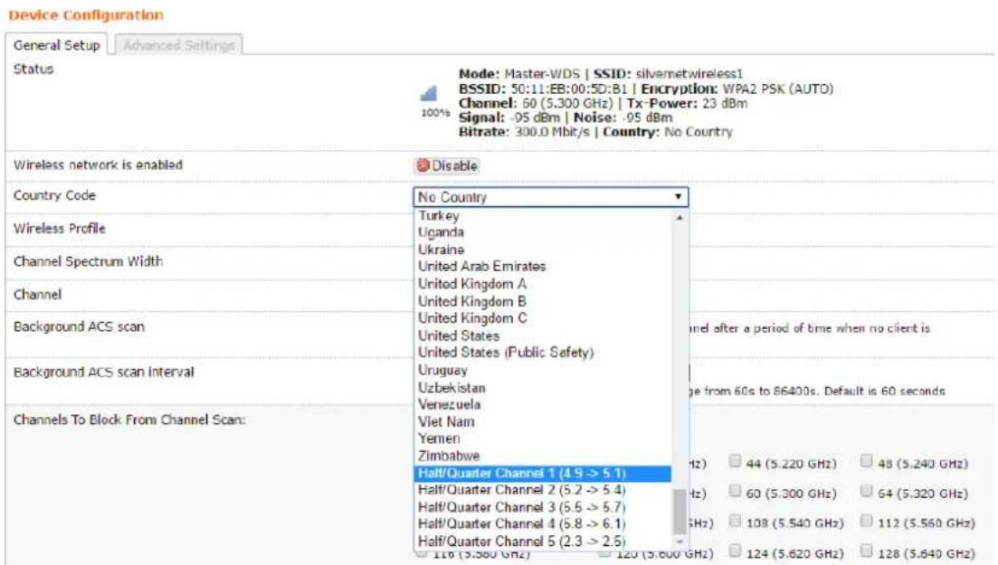
Refresh the page and then you will see 5MHz and 10MHz in Channel Spectrum Width.
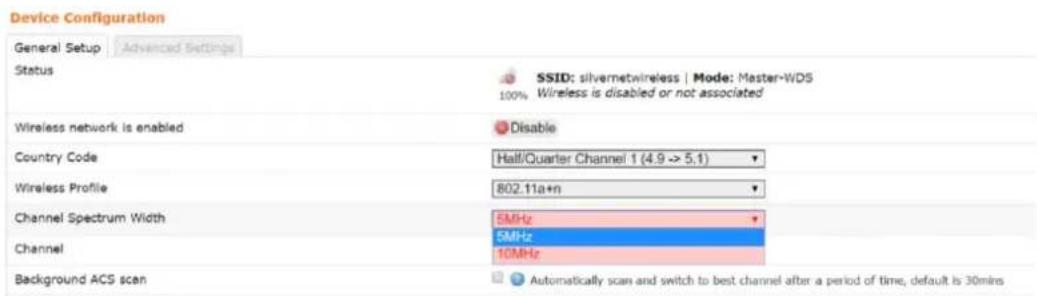
Choose 5MHz or 10MHz. Click Save & Apply to save the configuration.
Using higher bandwidth increases throughput. Using lower bandwidth reduces throughput.
Channel widths available are:
5 MHz - TX 32 - 20/25Mbps
10 MHz - TX 65 - 40/45Mbps
20 MHz - TX 130 - 90/95Mbps
20/40 MHz - TX 300 - 90/95Mbps - Both ways
ADVANCED SETTINGS
Device Configuration
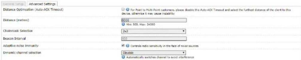
Distance Optimization If checked the distance will be optimised and the values for Slot Time, ACK Timeout, CTS Timeout will be calculated automatically. To specify the distance value, uncheck the box and manually enter the value.
Distance (metres) Specifies the distance between the AP and the station if the previous option is unchecked. Min: 300, Max: 24000 (40MHz), 48000 (20MHz). This value should be set to slightly more than the physical distance between the AP and the farthest station.
Chainmask Selection Available selections are:
- 1x1 Left Chain This will force the radio card to operate with 1 spatial stream on the left port of radio card only.
- 1x1 Right Chain This will force the radio card to operate with 1 spatial stream on the right port of radio card only.
- 2x2 Dual Chain This will enable the radio card to operate with 2 spatial streams on both radio card ports.
Beacon Interval This value indicates the frequency interval of the beacon. A beacon is a packet broadcast by the router which carries the SSID, channel number and security protocols. We recommend using the default setting of 100. In poor reception areas you may turn this down to 50.
Adaptive Noise Immunity Check to enable. When enabled, it automatically adjusts the signal/noise level for best performance. In a low noise environment, it is recommended you turn off this function.
Dynamic Channel Selection This is a feature to monitor traffic and noise levels. If the noise levels exceed the threshold, the AP will disconnect any associated stations and move to a new channel. The stations are expected to re-associate with the AP on their own. Available selections are:
- Look for CW Interference Use this feature to detect and avoid continuous wave (CW) interference.
- Look for WLAN Interference Use this feature to detect and avoid wireless interference
- Look for CW and WLAN Interference Use this feature to detect and avoid continuous wave (CW) interference and Wireless interference.
Interface Configuration
General Setup
Interface Configuration
| General Setup | Wireless Security | MAC-Filter | Advanced Settings |
| Mode | Access Point (WDS) ▼ | ||
| ESSID | silvermetwireless | ||
| Guard Interval | Short ▼ | ||
| Data Rate (Mbps) | Auto ▼ | ||
| Hide ESSID |
Mode Displays the operating mode of the radio interface. The Pro Range supports four operating modes:
- Station
- Station WDS
- Access Point
- Access Point WDS
Station If you have a client device to connect to an AP, configure the client device as Station mode.
The SSID of the AP is used, and it forwards all the traffic to/from the network devices to the Ethernet interface. This mode translates all the packets that pass through to its own MAC address, thus resulting in a lack of transparency.
Station WDS This mode is used to create a transparent bridge and can be connected to a device running in Access Point WDS mode.
NOTE Multiple stations or Stations WDS can connect to an AP WDS.
Access Point If you have a single device to act as an AP, configure it as Access Point mode. The device functions as an AP that connects multiple client devices
Access Point WDS This mode connects to a device running Station WDS mode. It is used to create a transparent bridge.
In most cases, we recommend that you use WDS because it enables transparent Layer 2 traffic. The WDS protocol is not defined as a standard, so there may be compatibility issues between equipment from different vendors.
ESSID If the device is operating in Access Point or Access point WDS mode, specify the wireless network name or SSID (Service Set Identifier) used to identify your WLAN. All the client devices within range will receive broadcast messages from the AP advertising this SSID. If the device is operating in Station mode, specify the SSID of the AP the device is to connect to.
BSSID Sets the MAC address of the AP. This option is available for a device operating as a station. This is useful because there can be multiple APs with the same ESSID. Setting the MAC address would prevent the station from roaming to other APs.
Guard Interval This is the space between symbols being transmitted. The Guard Interval is there to eliminate inter-symbol interference. For long distance connections, select Long to give better performance.
Data Rate Data Rates consist of both the legacy rates and the MCS (Modulation Coding Scheme – Only for 802.11n) rates.
6 – 54Mbps are Legacy Rates
MCSO to MCS7 are 802.11n rates
The MCS settings have different rates depending on the Chainmask Selection (see above for Chainmask Selection) that is used.
| Chainmask Selection | ||
| 1x1 | 2x2 | |
| MCS0 | 13.5Mbps | 27Mbps |
| MCS1 | 27Mbps | 54Mbps |
| MCS2 | 40.5Mbps | 81Mbps |
| MCS3 | 54Mbps | 108Mbps |
| MCS4 | 81Mbps | 162Mbps |
| MCS5 | 108Mbps | 216Mbps |
| MCS6 | 121.5Mbps | 243Mbps |
| MCS7 | 135Mbps | 300Mbps |
When left on auto the data rate will follow an advanced rate algorithm that considers the amount of errors at that data rate and fine tunes to the best data rate it can use.
Hide SSID Once checked, this will disable advertising the SSID of the access point in broadcast messages to wireless stations. This option is only available in Access Point and Access Point WDS mode.
TxCCQ Watchdog check to enable. This will monitor the signal quality of the link and if it falls below a certain threshold the device will reboot.
WIRELESS SECURITY
Interface Configuration

All the wireless security settings are set under this section.
The operation of the Keys is the same for ALL the Wireless modes.
Security The Pro 95 range supports the following wireless security methods:
No Encryption If you want an open network without wireless security, select No Encryption.
WEP Open System WEP (Wired Equivalent Privacy) is the oldest and least secure security algorithm.
WEP Shared Key WEP (Wired Equivalent Privacy) with slightly better authentication.
WPA-PSK WPA (Wi-Fi Protected Access) was developed as a stronger encryption method than WEP. This uses TKIP Temporal Key Integrity Protocol which uses RC4 encryption algorithm.
WPA2-PSK WPA2 was developed to strengthen wireless encryption security and is stronger than WEP and WPA. This is the most secure option. It uses the latest Wi-Fi encryption standard, and the latest AES (Advanced Encryption Standard) encryption protocol.
WPA2-PSK AES+ As above but with 256bit encryption.
WPA-PSK/WPA2-PSK Mixed Mode This enables both WPA and WPA2 with both TKIP and AES. This provides maximum compatibility with any ancient devices you might have.
IEEE802.1X/WPA-EAP This will require the equipment to be authenticated via a RADIUS server. The RADIUS server must support EAP or be chained/proxied to one that does.
IEEE802.1X/WPA2-EAP This will require the equipment to be authenticated via a RADIUS server. The RADIUS server must support EAP or be chained/proxied to one that does.
WEP
Note: Operating with WEP security will limit AP to maximum wireless link speed of 54Mbps only.
Encryption Select the type of encryption you want to use.
Open System (Default) No authentication. We recommend using this option over shared authentication.
Shared Key May not be compatible with all Access Points. Not recommended.
Used Key Slot Select which key to use
Key #1 Enter a security key to use
Key #2 Enter a security key to use
Key #3 Enter a security key to use
Key #4 Enter a security key to use
WPA/WPA2 AUTHENTICATION
The configuration options are the same for WPA and WPA2 authentication. WPA2-PSK is the strongest security method. If all wireless devices on your network support this option, we recommend that you select it.
Interface Configuration

Cipher Specify which of the following to use:
- Auto – Uses the most appropriate algorithm for the network
- CCMP (AES) - Advanced Encryption Standard (AES) algorithm. (default)
- TKIP and CCMP (AES) - Temporal Key Integrity Protocol which uses RC4 encryption algorithm and Advanced Encryption Standard (AES) algorithm.
Key The key is an alpha-numeric password between 8 and 63 characters long.
MAC-FILTER
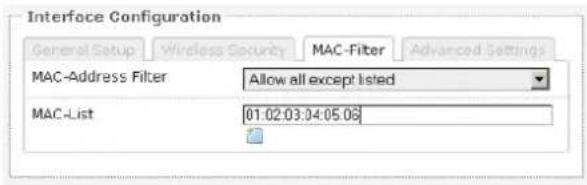
MAC-Address Filter Lets you allow only devices with the listed MAC address to associate with this AP, or lets you block devices with the listed MAC address.
Mac List Adds the MAC address of the remote device to either block or allow.
ADVANCED SETTINGS
Interface Configuration
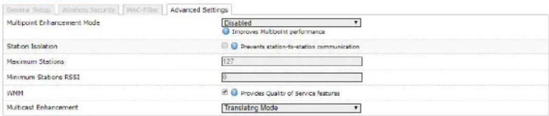
Multipoint Enhancement Mode Check to improve multipoint performance and show the RTS Threshold option. Enabling this will set the RTS to 538.
RTS Threshold This value is set to 2346 as default, which is the maximum 802.11 packet size. We recommend leaving this setting for Point to Point links, however, for Multipoint setups we recommend setting the RTS Threshold lower (538). The AP device sends Request to Send (RTS) frames to a receiving station and negotiates the sending of a data frame. After receiving an RTS, the wireless station responds with a Clear to Send (CTS) frame to acknowledge the right to begin transmission. The CTS contains a hold off time that prevents other clients from sending anything whilst the targeted client sends its data. Setting the RTS lower will improve the stability of a Multipoint setup.
Station Isolation When checked, it prevents station-to-station communication. When Station Isolation is disabled, wireless clients can communicate with one another normally by sending traffic through the AP. When Station Isolation is enabled, the AP blocks communication between wireless clients on the same AP.
Minimum Stations Specifies the maximum number of associated stations
Minimum Station RSSI When enabled, if the signal strength of any device connected to the AP falls below the value in this box, the AP will drop the connection.
WMM Provides Quality of Service (QoS) features. This is checked by default. Wireless multimedia (WMM) enables the classification of the network traffic into 4 main types, voice, video, best effort, and background, in decreasing order of priority. Higher priority traffic has a higher transmission opportunity and would have to wait less time to transmit. As a result, an existing video stream would not be interrupted by additional background processes.
Multicast Enhancement Available selections are:
- Selective Passthrough Use this feature when no multicast traffic is expected to cross the link aside from SSDP traffic (such as ONVIF) from AP to ST.
- Tunnelling Mode Use this feature when multicast traffic is only required across the link from ST to AP.
- Translating mode Use this feature to send out a unicast packet to each of the units on the ST side that are interested in multicast traffic for a particular address.
Multicast Enhancement is designed to limit the proliferation of multicast traffic on a network by only forwarding packets from an AP to an STA if the AP knows there is a unit interested in that traffic on the STA side of the link. All multicast traffic should be passed from an STA to an AP.
If no multicast traffic is expected to cross the link aside from SSDP traffic (such as ONVIF) from AP to STA, Selective Passthrough should be chosen for the Multicast Enhancement setting.
If multicast traffic is only required to travel across the link from STA to AP, Multicast Enhancement Mode should be set to Tunnelling Mode at both ends of a link.
In a situation where multicast traffic is required in both directions, say where a camera is producing a multicast stream and you wish to monitor this via ONVIF, both ends of the link should be set to Tunnelling Mode and an IGMP Querier should be present on the AP side of the network with a query interval of 2 minutes. The IGMP Querier ensures that all multicast capable devices on the local network inform the AP which multicast addresses they are interested in. Most managed switches should have the capability of being an IGMP Querier but in the case where no such switch exists on the network, it is possible to use an additional inexpensive managed switch to provide this functionality.
Multicast enhancement is only available on the Pro Range 95 models.
VLANS
The VLANS tab contains everything needed to set up VLANS.

VLAN ACTIVATION
VLAN ACTIVATION
| Enable VLAN |
Enable VLAN Check to enable VLANS
VLAN ENTRIES
VLAN entries
| VLAN ID | Priority | Protocol | IPv4 address | IPv4 netmask | ath0 | eth0 | eth1 | Description | |||
| Master-WDS "silvernetwireless" | Ethernet Switch (Right Port, PoE input) | Ethernet Adapter (Left Port, PoE output) | |||||||||
| 3355 | 0 | ▼ | Static | 0.0.0.0 | 255 255 257 | off | off | ▼ | off | ▼ | VLAN Network □ Delete |
| 100 | 0 | ▼ | Static | 192.168.1.100 | 255 255 257 | off | lagged | ▼ | off | ▼ | Management □ Delete |
VLAN ID Enter the VLAN ID you wish to use
Priority Set the priority of the VLAN
Protocol Choose static address or DHCP
IPv4 Address Enter the IP address you want to use
IPv4 Netmask Enter the subnet you want to use
Ath0 Choose to leave off, or Tag or Untag the wireless interface
Eth0 Choose to leave off, or Tag or Untag the Ethernet LAN interface
Eth1 Choose to leave off, or Tag or Untag the Ethernet WAN interface
Only the LAN interface is currently used in these devices. Leave as off.
Description Enter a VLAN description
Delete Delete the VLAN
To enable management only through the VLAN ID you have entered you will need to return to the Admin tab. Under the Administration section you will see the interfaces. Choose to only enable web access from the VLAN interface.
Web
Provides administrator tools to control the device

VLAN MANAGEMENT SETUP
VLAN entries

In this example, we will set up a Management VLAN on ID 100.
Once this is done you will only be able to gain access to the web page if you are on the same VLAN ID.
Set up
- Add a new VLAN
- Enter the VLAN ID (100)
- Set the Priority (this can be left at 0)
- Set the protocol to static
- Enter the IP address you wish to use for the device
- Enter the subnet mask
- Set eth0 to tagged eth0 is the ethernet LAN interface
- Edit the description
Once you have configured the above, you will need to tick the Enable VLAN option at the top of the page.
VLAN ACTIVATION

You will now only be able to access the radio on VLAN 100
STANDARDS
DECLARATION OF CONFORMITY
SilverNet Limited declares the following:
Product Name: Pro Range 95
Model No.: PICO 95, MICRO 95, LITE 95, MAX 95 conforms to the following Product Standards:
This device complies with the Electromagnetic Compatibility Directive (89/336/EEC) issued by the Commission of the European Community. Compliance with this directive implies conformity to the following European Norms (in brackets are the equivalent international standards.)
Electromagnetic Interference (Conduction and Radiation): EN 55022 (CISPR 22)
Electromagnetic Immunity: EN 55024 (IEC61000-4-2, 3, 4, 5, 6, 8, 11)
Low Voltage Directive: EN 60 950: 1992+A1: 1993+A2: 1993+A3: 1995+A4: 1996+A11: 1997.
Therefore, this product is in conformity with the following regional standards:
FCC Class B: following the provisions of FCC Part 15 directive,
CE Mark: following the provisions of the EC directive.
SilverNet Limited also declares that:
The wireless card in this product complies with the R&TTE Directive (1999/5/EC) issued by the Commission of the European Community. Compliance with this directive implies conformity to the following:
EMC Standards: FCC: 47 CFR Part 15, Subpart B, 47 CFR Part 15, Subpart C (Section 15.247); CE: EN 300 328-2, EN 300 826 (EN 301 489-17)
Therefore, this product is in conformity with the following regional standards:
FCC Class B: following the provisions of FCC Part 15 directive,
CE Mark: following the provisions of the EC directive.
WARNINGS
RADIO FREQUENCY INTERFERENCE REQUIREMENTS
The operation of this device in the 5.15 GHz to 5.25 GHz frequency range is restricted to indoor use. FCC regulations require this product to be used indoors while operating at 5.15 GHz to 5.25 GHz to reduce the potential for harmful interference. However, the operation of this device in the 5.25 GHz to 5.35 GHz frequency range is allowed for both indoor and outdoor use. High power radars are allocated as primary users of the 5.25 GHz to 5.35 GHz and 5.65 GHz to 5.85 GHz bands. These radar stations can cause interference with and/or damage to this device.
FCC Warning
This equipment has been tested and found to comply with the limits for a Class B digital device, pursuant to Part 15 of the FCC Rules. These limits are designed to provide reasonable protection against harmful interference in a residential installation. This equipment generates, uses, and can radiate radio frequency energy and, if not installed and used in accordance with the instructions, may cause harmful interference to radio communications. No guarantee exists that interference will not occur in a particular installation. If this equipment does cause harmful interference to radio or television reception (determined by turning the equipment off and on), the user is encouraged to try to correct the interference by one or more of the following measures:
- Reorient or relocate the radio/TV receiving antenna.
- Increase the separation between the equipment and the radio/TV receiver.
- Connect the equipment into an outlet on a circuit different from that to which the radio/TV receiver is connected.
- Consult the dealer or an experienced radio/TV technician for help. Modifications made to the product, unless expressly approved by SilverNet Limited, could void the user's authority to operate the equipment.
RF Exposure Requirements
To ensure compliance with FCC RF exposure requirements, the antenna used for this device must be installed to provide a separation distance of at least 20 cm from all persons and must not be co-located or operating in conjunction with any other antenna or radio transmitter. Installers and end-users must follow the installation instructions provided in this user guide.
CE Statement
The Pro Range 95 is intended to be used by suitably trained individuals or organisations that are familiar with the requirements of the R&TTE directive. In particular the client must ensure that appropriate antennas and transmit power levels are selected to ensure that all power limits are met. Hereby, SilverNet Limited declares that this device is in compliance with the essential requirements and other relevant provisions of the R&TTE Directive 1999/5/EC. However, the use of the following warning symbol
CE!
Means that this equipment is subject to restrictions of use in certain countries and selection of the correct country of operation (country code) will ensure that the device operates only on the frequencies permissible within that country. It is also the operator's responsibility to ensure that appropriate licenses have been sought when operating on licensed frequencies, for example UK Band C, 5725-5850MHz.
In the UK, all radios operate under the control of Ofcom. Radio use in the 2.4 & 5GHz bands are deemed to be Licence Exempt with the exception of Band C. Band C (5.725 to 5.825GHz) requires registration with Ofcom under a light licensing scheme. While this band is still effectively licence exempt, Ofcom wants to keep a register of all FWA links and charges a small fee. Any user wishing to set up an outdoor link for FWA needs to apply to Ofcom for a site license; the licence is not hard to obtain and is only £50 which includes registration of up to 50 terminals. For every terminal beyond 50 you should add £1 to the cost of your licence.
Further information on the legal implications of Band C usage can be found on the Ofcom website.
TROUBLESHOOTING
If you are having problems with your links, then please check the following before calling our support team.
Line of Sight - The radios work best when they have line-of-sight. If the radios do not have line-of-sight, then you will get a very poor signal or no signal at all.
Alignment - If the radios are not aligned correctly the signal quality of the radios will suffer and you may not receive the throughput you require. Run SilverView and use the data test tool.
Power - If the units are not powering on then you will need to test the Ethernet cable and re-terminate it if required. We recommend outdoor shielded grade cable for all installations. Please also check that the PSU is plugged in and turned on.
Interference - Our radios use auto-channel select and should avoid interferences as best as possible. Rebooting the radios will allow a re-scan. If you are experiencing interference problems when using the radios, try setting them on a static channel. Try each channel until you find one that gives you a better signal. Use SilverView and run a data test.
WARRANTY
The Pro Range 95 comes with a 2 year warranty as standard. For full terms and conditions of warranty please go to www.silvernet.com/terms-and-conditions/
CONTACT SILVERNET
Email us at support@silvernet.com
Call our support team on 08712233067
www.silvernet.com
COPYRIGHT INFORMATION
Copyright ©2019 all rights reserved. No part of this publication may be reproduced, adapted, stored in a retrieval system, translated into any language, or transmitted in any form or by any means without the written permission of the supplier.
OTHER SILVERNET PRODUCTS
PRO RANGE
natural_image
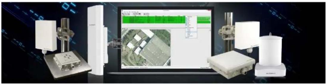
Industrial testing setup with robotic arms, a laptop displaying a 3D map, and a cylindrical device (no visible text or symbols)INDUSTRIAL NETWORK TRANSMISSION
INTELLIGENT WI-FI SOLUTIONS
INDUSTRY LEADING TECHNICAL SUPPORT

- TABLE OF CONTENTS
- INTRODUCTION
- SUPPORTED PRODUCTS
- WIRELESS MODES
- SYSTEM REQUIREMENTS
- PACKING LIST
- THE ENCLOSURE AND LED INDICATORS
- CONFIGURATION
- GETTING STARTED
- NAVIGATION
- Status Admin Services Network Logout
- STATUS TAB
- OVERVIEW
- Wireless parameters
- Associated stations parameters
- REALTIME GRAPHS
- Realtime Connections
- ADMIN TAB
- SYSTEM
- System Properties
- Time Synchronisation
- General Settings
- Logging
- ADMINISTRATION
- Radio Password
- Web
- SNMP
- SNMP Information
- SNMP Configuration
- Enable SNMP Enable SNMP
- SNMP TRAP
- LED CONFIGURATION
- BACKUP/FLASH FIRMWARE
- Flash operations
- Backup / Restore
- Flash new firmware
- Reboot
- SERVICES TAB
- Ping Watchdog and Auto Reboot
- PING WATCHDOG
- AUTO REBOOT
- DYNAMIC DNS
- NETWORK TAB
- Interfaces
- Interface Overview
- Network
- Status
- Actions
- LAN INTERFACE
- Interfaces - LAN
- DHCP Server
- Static Leases
- Common Configuration
- General Setup
- Advanced Settings
- Physical Settings
- WIRELESS INTERFACE
- Wireless Overview
- Associated Stations
- SPECTRUM SCANS
- Click the Scan button to perform a spectrum scan from the Station
- Join Network: Wireless Scan
- CONFIGURATION PAGES
- DEVICE CONFIGURATION
- 5MHz and 10MHz Channel Spectrum Width
- Chainmask Selection Available selections are:
- Interface Configuration
- WIRELESS SECURITY
- WEP
- WPA/WPA2 AUTHENTICATION
- MAC-FILTER
- Multicast Enhancement Available selections are:
- VLANS
- VLAN ACTIVATION
- VLAN ENTRIES
- VLAN MANAGEMENT SETUP
- Set up
- STANDARDS
- DECLARATION OF CONFORMITY
- WARNINGS
- RADIO FREQUENCY INTERFERENCE REQUIREMENTS
- FCC Warning
- RF Exposure Requirements
- CE Statement
- CE!
- TROUBLESHOOTING
- WARRANTY
- CONTACT SILVERNET
- COPYRIGHT INFORMATION
- OTHER SILVERNET PRODUCTS
Brand : SilverNet
Model : Micro 95
Category : Wi-Fi repeater