
CR 12 - Saw HITACHI - Free user manual and instructions
Find the device manual for free CR 12 HITACHI in PDF.


| Product type | Electric jigsaw |
| Brand | Hitachi |
| Model | CR 12 |
| Dimensions (L x W x H) | 250 x 80 x 200 mm |
| Weight | 1.8 kg |
| Power supply | 230 V, 50 Hz |
| Power consumption | 600 W |
| Variable speed | 500 - 3000 strokes/min |
| Blade stroke | 20 mm |
| Cutting capacity wood | Up to 90 mm |
| Cutting capacity steel | Up to 10 mm |
| Main functions | Plunge cutting, laser guide, chip blower |
| Blade type | T-shank blades (universal) |
| Maintenance and cleaning | Clean after each use, check brushes regularly |
| Safety | Trigger with lock, automatic overload shut-off |
| Spare parts and repairability | Blades, brushes, shoe pads available online |
| General information | Domestic and light professional use |
| Noise level | 90 dB(A) |
| Vibration | Medium, anti-vibration handle |
| Included accessories | 1 blade, parallel guide, hex key |
Frequently Asked Questions - CR 12 HITACHI
User questions about CR 12 HITACHI
0 question about this device. Answer the ones you know or ask your own.
Ask a new question about this device
Download the instructions for your Saw in PDF format for free! Find your manual CR 12 - HITACHI and take your electronic device back in hand. On this page are published all the documents necessary for the use of your device. CR 12 by HITACHI.
USER MANUAL CR 12 HITACHI
natural_image
Technical line drawing of a mechanical tool with no visible text or symbolsRead through carefully and understand these instructions before use.
natural_image
Illustration of a hand holding a medical or robotic arm with a tool, no text or symbols present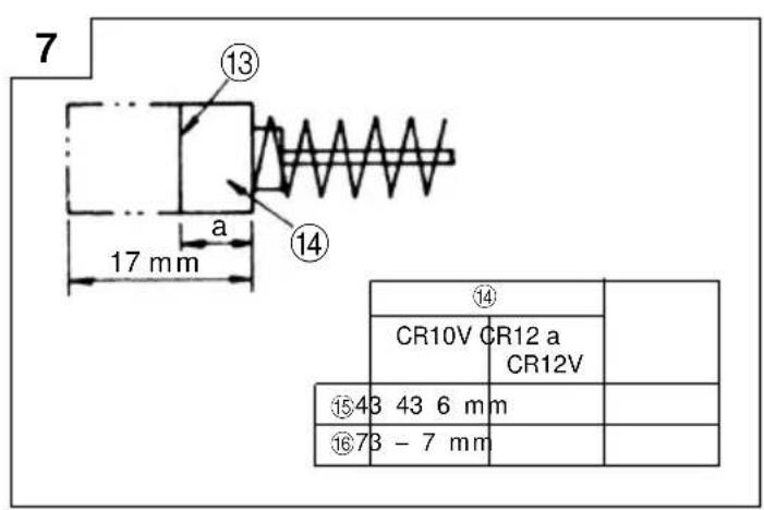
| English Deutsch | Français Italiano | |||
| 1 | Dial Skala Cadran Selettore | |||
| 2 | Change lever Wechselknopf Bouton de changement | Rotella di cambio | ||
| 3 | Hexagonal bar wrench Sechskantschlüssel Clef à barre hexagonale | Chiave esagonale maschia | ||
| 4 | Set screw 14mm Klemmschraube 14mm Vis de fixation 14mm Vite di fissaggio, 14mm | |||
| 5 | Insulation cover Gummischutzüberzug Gaine d'isolation Coperchio isolante | |||
| 6 | Plunger | Schwingspule Piston | Pistone | |
| 7 | Blade | Sägeblatt | Lame | Lama |
| 8 | Hole | Loch | Trou | Foro |
| 9 | Blade holder | Sägeblatthalter | Porte-lame | Portalama |
| 10 | Projection part | Vorsprung | Saillie | Parte sporgente |
| 11 | Base | Führungstisch | Base | Basamento |
| 12 | Set screw 12mm Klemmschraube 12mm Vis de fixation 12mm Vite di fissaggio, 12mm | |||
| 13 | Wear limit | Verschleißgrenze Limite d'usure Limited | di usura | |
| 14 | No. of carbon brush | No der Kohlebürste | No. de balai en carbone | N. delle spazzole di carbone |
| 15 | Usual carbon brush | Gewöhnliche Kohlebürste | Balai en carbone Spazzola ordinaire | di carbone comune |
| 16 | Auto-stop carbon brush | Auto-Stop Kohlebürste | Balai en carbone à arrêt automatique | Spazzola di carbone ad arresto automatico |
| Nederlands | Español | Português | Ελληνικά | |
| 1 | Schijf | Selector | Seletor | Καντράν |
| 2 | Omstelknop | Perilla de cambio | Alavanca de câmbio | Μοχλός αλλαγής |
| 3 | Inbussleutel | Llave macho hexagonal | Chave de barra sextavada | Εξάγωνο κλειδί Άλεν |
| 4 | Stelschroef 14mm | Tornillo de ajuste de 14mm | Parafuso de retenção de 14 mm | Ρυθμιστική βίδα 14mm |
| 5 | Isolatiekap | Cubierta de aislamiento | Cobertura de isolamento | Μονωτικό κάλυμμα |
| 6 | Plunjer | Embolo vástago | Pistão | Έμβολο |
| 7 | Zaagblad | Cuchilla | Lâmina | Λεπίδα |
| 8 | Opening Orificio | Orifício | Τρύπα | |
| 9 | Zaagbladhouder | Sujetador de cuchilla | Suporte de lâmina | Στήριγμα λεπίδας |
| 10 | Uitsteeksel | Parte sobresaliente | Parte saliente | Προεξέχων τμήμα |
| 11 | Basis | Base | Base | Βάση |
| 12 | Stelschroef 12mm | Tornillo de ajuste de 12mm | Parafuso de retenção de 12 mm | Ρυθμιστική βίδα 12mm |
| 13 | Slijtagelimiet | Límite de uso | Limite de desgaste | Όριο φθοράς |
| 14 | No van de koolborstel | No. de la escobilla de carbón | No da escova de carvão | Αρ. καρβουνακίων |
| 15 | Normale koolborstel | Escobilla de carbón normal | Escova de carvão normal | Συνηθισμένο καρβουνάκι |
| 16 | Auto-stop koolborstel | Escobilla de carbón de parada automática | Escova de carvão de parada automática | Καρβουνάκι αυτόματης διακοπής |
GENERAL OPERATIONAL PRECAUTIONS
WARNING! When using electric tools, basic safety precautions should always be followed to reduce the risk of fire, electric shock and personal injury, including the following.
Read all these instructions before operating this product and save these instructions.
For safe operations:
- Keep work area clean. Cluttered areas and benches invite injuries.
- Consider work area environment. Do not expose power tools to rain. Do not use power tools in damp or wet locations. Keep work area well lit. Do not use power tools where there is risk to cause fire or explosion.
- Guard against electric shock. Avoid body contact with earthed or grounded surfaces. (e.g. pipes, radiators, ranges, refrigerators).
- Keep children away. Do not let visitors touch the tool or extension cord. All visitors should be kept away from work area.
- Store idle tools. When not in use, tools should be stored in a dry, high or locked up place, out of reach of children.
- Do not force the tool. It will do the job better and safer at the rate for which it was intended.
- Use the right tool. Do not force small tools or attachments to do the job of a heavy duty tool. Do not use tools for purposes not intended; for example, do not use circular saw to cut tree limbs or logs.
- Dress properly. Do not wear loose clothing or jewellery, they can be caught in moving parts. Rubber gloves and non-skid footwear are recommended when working outdoors. Wear protecting hair covering to contain long hair.
- Use eye protection. Also use face or dust mask if the cutting operation is dusty.
- Connect dust extraction equipment. If devices are provided for the connection of dust extraction and collection facilities ensure these are connected and properly used.
- Do not abuse the cord. Never carry the tool by the cord or yank it to disconnect it from the receptacle. Keep the cord away from heat, oil and sharp edges.
- Secure work. Use clamps or a vise to hold the work. It is safer than using your hand and it frees both hands to operate tool.
- Do not overreach. Keep proper footing and balance at all times.
- Maintain tools with care. Keep cutting tools sharp and clean for better and safer performance. Follow instructions for lubrication and changing accessories. Inspect tool cords periodically and if damaged, have it repaired by authorized service center. Inspect extension cords periodically and replace, if damaged. Keep handles dry, clean, and free from oil and grease.
-
Disconnect tools. When not in use, before servicing, and when changing accessories such as blades, bits and cutters.
-
Remove adjusting keys and wrenches. Form the habit of checking to see that keys and adjusting wrenches are removed from the tool before turning it on.
- Avoid unintentional starting. Do not carry a plugged-in tool with a finger on the switch. Ensure switch is off when plugging in.
- Use outdoor extension leads. When tool is used outdoors, use only extension cords intended for outdoor use.
- Stay alert. Watch what you are doing. Use common sense. Do not operate tool when you are tired.
- Check damaged parts. Before further use of the tool, a guard or other part that is damaged should be carefully checked to determine that it will operate properly and perform its intended function. Check for alignment of moving parts, free running of moving parts, breakage of parts, mounting and any other conditions that may affect its operation. A guard or other part that is damaged should be properly repaired or replaced by an authorized service center unless otherwise indicated in this handling instructions. Have defective switches replaced by an authorized service center. Do not use the tool if the switch does not turn it on and off.
- Warning
The use of any accessory or attachment, other than those recommended in this handling instructions, may present a risk of personal injury. - Have your tool repaired by a qualified person. This electric tool is in accordance with the relevant safety requirements. Repairs should only be carried out by qualified persons using original spare parts. Otherwise this may result in considerable danger to the user.
PRECAUTIONS ON USING SABER SAW
Prior to cutting into walls, ceilings or floors, ensure there are no electric cables or conduits inside.
SPECIFICATIONS
| Model CR10V CR12 CR12V | |||
| Voltage (by areas)* (110V, 115V, 120V, 127V, 220V, 230V, 240V) | |||
| Power Input 720W* | |||
| Capacity Mild Steel Pipe: O.D. 115 mm | Vinyl Chloride Pipe: O.D. 115 mmWood: Thickness 100 mmMild Steel Plate: Thickness 13 mm | ||
| No-Load Speed 700 - 2200/min 2500/min | 800 - 2500/min | ||
| Stroke 26 mm 30 mm | |||
| Weight (without cord and side handle) | 3.6 kg | 3.2 kg | |
* Be sure to check the nameplate on product as it is subject to change by areas.
STANDARD ACCESSORIES
(1) Blade (No.1, No.3, No.5) [CR10V].... 1 each Blade (No.1) [CR12, CR12V] .... 1 Refer to tables 1 and 2 for use of the blades.
(2) Hexagonal bar wrench 1
(3) Case [CR10V, CR12V] 1
Standard accessories are subject to change without notice.
OPTIONAL ACCESSORIES (sold separately)
(1) No. 2 Blade
(2) No. 4 Blade
(3) No. 6 Blade
(4) No. 7 Blade
(5) No. 8 Blade
(6) No. 9 Blade
(7) No. 95 Blade
(8) No. 96 Blade
(9) Cut-off Guide for Pipe
Refer to tables 1 and 2 for use of the blades.
Optional accessories are subject to change without notice.
APPLICATIONS
○Cutting pipe and angle steel.
○Cutting various lumber.
○Cutting mild steel plate, aluminum plate, and copper plate.
○Cutting synthetic resins, such as phenol resin and vinyl chloride.
For details refer to the section entitled “Selection of blades”
PRIOR TO OPERATION
1. Power source
Ensure that the power source to be utilized conforms to the power requirements specified on the product nameplate.
2. Power switch
Ensure that the power switch is in the OFF position. If the plug is connected to a receptacle while the power switch is in the ON position, the power tool will start operating immediately, which could cause a serious accident.
3. Extension cord
When the work area is removed from the power source, use an extension cord of sufficient thickness and rated capacity. The extension cord should be kept as short as practicable.
4. Adjusting the blade operating speed (CR10V, CR12V)
The machine is equipped with an electric control circuit which enables non-step speed control. To adjust the speed, turn the dial shown in Fig. 1. When the dial is set to "1", the saber saw operates at the minimum speed (CR10V: 700/min, CR12V: 800/min). When the dial is set to "5", the saber saw operates at the maximum speed (CR10V: 2200/min, CR12V: 2500/min). Adjust the speed according to the material to be cut and working efficiency.
5. Adjusting the orbital operation (CR10V)
(1) This machine employs orbital operation which moves the blade back and forth, as well as up and down. Set the change lever shown in Fig 2 to "1" to minimize the orbital operation. The orbital operation can be selected in 3 steps from "I" to "III".
(2) For hard material, such as a steel plate, etc., decrease the orbital operation. For soft material, such as lumber, plastic, etc., increase the orbital operation to increase work efficiency. To cut the material accurately, decrease the orbital operation.
6. Mounting the blade
Insert the blade between the plunger and the blade holder, and tighten the set screw with the accessory hexagonal bar wrench, as shown in Fig. 3.
When inserting the blade, ensure that the projection part of the blade holder is properly fitted to the matching hole in the blade, as shown in Fig. 4.
CAUTION
A loosened set screw may cause the blade to be damaged. Always ensure that the set screw is securely tightened.
7. Moving the base
Loosen the set screw and move the base forward, as shown in Fig. 5. Tighten the set screw slightly, ensure the base does not move back and forth, and firmly tighten the set screw. Ensure that the base does not contact the blade.
8. Confirm the blade clamping
Ensure that the blade setscrew is securely tightened.
HOW TO USE
CAUTIONS
○Do not remove the insulation cover. It is necessary to support the body of the tool.
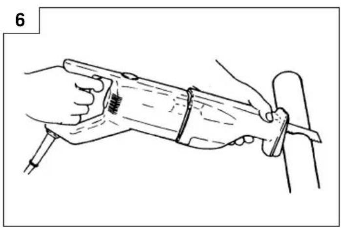
During operation, the base of the tool should be pressed against the material, as shown in Fig. 6, herein. If the tool is not properly pressed against the maerial, the blade may be damaged by vibration.
1. Cutting metallic materials
Ensure the material is firmly held in position during operation. Always use an appropriate cutting agent (spindle oil, soapy water, etc.). When a liquid cutting agent is not available, apply grease to the material to be cut.
2. Cutting lumber
When cutting lumber, ensure that the wooden material is firmly fixed in position.
3. Sawing curved lines
Use a No. 6 or No. 7 blade (optional accessories) as described below.
○For metal-working - No. 6
○For wood-working - No. 7
When sawing a small circular arc, reduce the feeding speed of the machine.
4. Cut off guide for cutting pipe (optional accessory)
| Product | Cutting Blade application | Applicable used products | Code No. |
| Cut-off Outer diameter guide (L) | 75mm - 175mm | No. 9 | Model CR10V 984449 |
| Model CR12, CR12V 996420 | |||
| Cut-off Outer diameter guide (S) | 10mm - 55mm | No. 1 | Model CR10V 984448 |
| Model CR12, CR12V 996429 |
NOTE
Please refer to the cut off guide user's manual for details on how to use ti correctly.
SELECTION OF BLADES
To ensure maximum operating efficiency and results, it is very important to select the appropriate blade best suited to the type and thickness of the material to be cut. Three types of blades are provided as standard accessories.
The blade number is engraved in the vicinity of the mounting position of each blade. Select appropriate blades by referring to Tables 1 and 2 below.
Table 1
| Blade No. (mm) | Uses | Thickness |
| No.1 | For cutting steel pipe less than 115mm in diameter | 2.5 – 6 |
| No.2 | For cutting steel pipe less than 40mm in diameter | 2.5 – 6 |
| No.3 | For cutting steel pipe less than 40mm in diameter | Below 3.5 |
| Blade No. (mm) | Uses | Thickness |
| No.4 | For cutting and roughing lumber | 50 – 100 |
| No.5 | For cutting and roughing lumber | Below 50 |
| No.6 | For sawing curved lines iron plate | Below 3.5 |
| No.7 | For sawing curved lines lumber | Below 30 |
| No.8 | For cutting vinyl chloride pipe less than 115mm in diameter | 2.5 – 15 |
| For cutting and roughing lumber | Below 50 | |
| No.9 | For cutting mild steel pipe less than 175mm in diameter when used with cut off guide | 2.5 – 6 |
| No.95 | For cutting stainless steel pipe less than 115mm in diameter | Below 2.5 |
| No.96 | For cutting stainless steel pipe less than 40mm in diameter | Below 2.5 |
NOTE
No. 2, No. 4, No. 6, No. 7, No. 8, No. 9, No. 95, and No. 96 blades are sold separately.
For other materials.
Table 2
| Material to be cut | Material quality (mm) No. | Thickness | Blade |
| Iron plate | Mild steel plate | Below 3.52.5 – 12 | No.3,6No.1,2 |
| Nonferrous metal | Aluminium, Below Copper, Brass | 5 No.3,65 – 20 | No.1,2 |
| Synthetic restin | Phenol resin,Melamine resin, etc. | 5 – 30 No10 – 50 | No.3,5,8No.1,2,4, |
| Vinyl chlorideAcrylic resin, etc. | 5 – 30 No10 – 60 | No.3,5,8No.1,2,4 |
MAINTENANCE AND INSPECTION
1. Inspecting the blade
Continued use of a dull or damaged blade will result in reduced cutting efficiency and may cause overloading of the motor. Replace the blade with a new one as soon as excessive abrasion is noted.
2. Inspecting the mounting screws:
Regularly inspect all mounting screws and ensure that they are properly tightened. Should any of the screws be loose, retighten them immediately. Failure to do so could result in serious hazard.
3. Maintenance of the motor
The motor unit winding is the very “heart” of the power tool. Exercise due care to ensure the winding does not become damaged and/or wet with oil or water.
4. Inspecting the carbon brushes (Fig.7)
The Motor employs carbon brushes which are consumable parts. When they become worn to or near the “wear limit”, it could result in motor trouble. When an auto-stop carbon brush is equipped, the motor will stop automatically.
At that time, replace both carbon brushes with new ones which have the same carbon brush Numbers shown in the figure. In addition, always keep carbon brushes clean and ensure that they slide freely within the brush holders.
5. Replacing carbon brush:
Disassemble the brush caps with a slotted-head screwdriver. The carbon bushes can then be easily removed.
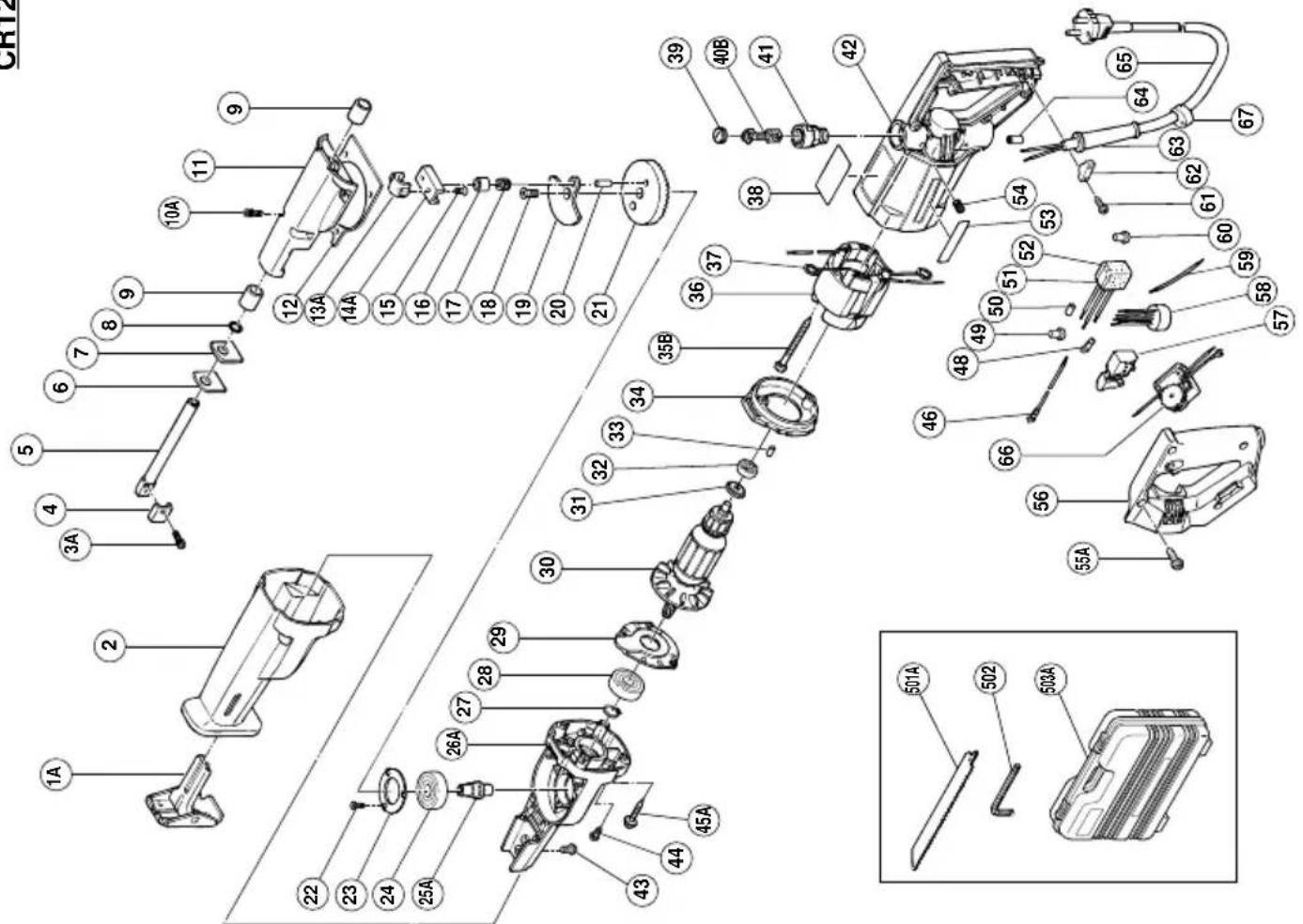
6. Service parts list
A: Item No.
B: Code No.
C: No. Used
D: Remarks
CAUTION
Repair, modification and inspection of Hitachi Power Tools must be carried out by an Hitachi Authorized Service Center.
This Parts List will be helpful if presented with the tool to the Hitachi Authorized Service Center when requesting repair or other maintenance.
In the operation and maintenance of power tools, the safety regulations and standards prescribed in each country must be observed.
MODIFICATIONS
Hitachi Power Tools are constantly being improved and modified to incorporate the latest technological advancements.
Accordingly, some parts (i.e. code numbers and/or design) may be changed without prior notice.
NOTE
Due to HITACHI's continuing program of research and development, the specifications herein are subject to change without prior notice.
IMPORTANT
Correct connection of the plug
The wires of the main lead are coloured in accordance with the following code:
Blue: - Neutral
Brown: - Live
As the colours of the wires in the main lead of this tool may not correspond with the coloured markings identifying the terminals in your plug proceed as follows: The wire coloured blue must be connected to the terminal marked with the letter N or coloured black. The wire coloured brown must be connected to the terminal marked with the letter L or coloured red. Neither core must be connected to the earth terminal.
NOTE
This requirement is provided according to BRITISH STANDARD 2769: 1984.
Therefore, the letter code and colour code may not be applicable to other markets except The United Kingdom.
Information concerning airborne noise and vibration
The measured values were determined according to EN50144.
The typical A-weighted sound pressure level: 88 dB (A)(CR10V), 89dB (A)(CR12V), .
The typical A-weighied sound power level: 101 dB (A)(CR10V), 102 dB (A)(CR12V).
Wear ear protection.
The typical weighted root mean square acceleration value: 8.5 m/s ^2 (CR10V), 9.5 m/s ^2 (CR12V),
CR12V
| A | B | C | D | A | B | C | D |
| 1A 996-452 1 | 36 6 983-580K 1 | 110V "37" "GBR" | |||||
| 2 996-397 1 | 37 930-703 2 | ||||||
| 3A 318-316 1 M5·15 | 38 ———— 1 | ||||||
| 4 956-608 1 | 39 961-781 2 | ||||||
| 5 996-394 1 | 40 999-043 2 | ||||||
| 6 996-401 1 | 41 981-586 2 | ||||||
| 7 996-400 1 | 42 983-552 1 "41, 54" | ||||||
| 8 996-407 1 1AP-12 | 43 996-399 2 M5·12 | ||||||
| 9 956-589 2 | 44 987-203 3 M4·12 | ||||||
| 10A 305-574 4 M5·16 | 45A 931-875 4 D5·35 | ||||||
| 11 996-396 1 "9" | 46 981-534 1 | ||||||
| 12 996-406 1 | 48 980-063 1 | ||||||
| 13A 993-567 1 | 49 959-140 2 | ||||||
| 14A 996-405 1 | 50 981-373 2 | ||||||
| 15 983-550 2 M5·12 | 51 994-273 1 | ||||||
| 16 983-541 1 | 52 930-153 1 | ||||||
| 17 983-560 1 H-7108 | 53 957-561 1 | ||||||
| 18 983-609 1 M6·16 | 54 961-681 2 M4·5 | ||||||
| 19 996-395 1 | 55A 301-563 5 D4·20 | ||||||
| 20 983-558 1 D7 | 56 983-572 1 | ||||||
| 21 996-393 1 "20" | 57 1 957-747 1 | ||||||
| 22 993-244 3 M4·12 | 57 2 963-756Z 1 "FRA, AUS" | ||||||
| 23 996-392 1 | 57 3 971-667Z 1 "GBR, ITA, FRG, HOL, AUT" | ||||||
| 24 620-2VV 1 6202VVCMPS2S | |||||||
| 25A 984-446 1 | 58 958-263 1 "NZL" | ||||||
| 26A 996-428 1 | 59 ———— 1 | ||||||
| 27 939-542 1 | 60 959-141 1 | ||||||
| 28 620-1VV 1 6201VVCMPS2S | 61 984-750 2 D4·16 | ||||||
| 29 996-390 1 | 62 960-266 1 | ||||||
| 30 1 360-070 1 110V-127V | 63 1 953-327 1 D8.8 | ||||||
| 30 2 360-070E 1 220V-230V | 63 2 938-051 1 D10.1 | ||||||
| 30 3 360-070F 1 240V | 64 981-373 2 | ||||||
| 31 956-387 1 | 65 ———— 1 | ||||||
| 32 608-VVM 1 | 608VVMC2EPS2L | 66 1 983-577 1 100V-127V | |||||
| 33 946-362 1 | 66 2 983-583Z 1 220V-240V | ||||||
| 34 981-562 1 | 67 940-928 1 | ||||||
| 35B 961-501 2 D5·60 | 50IAA 959-610 1 | ||||||
| 36 1 983-580C 1 | 110V-127V "37" | 502 944-458 1 | |||||
| 36 2 983-580E I | 220V-240V "37" | 503A 310-905 I | |||||
| 36 3 983-580F I 2 "SIN, KUW, NGU" | |||||||
| 36.4.983-580H I | 220V-230V "37" "NZL, SAF, AYT, SUI" "AUS, GBR, FRG, FRA, HOL, ESP" | ||||||
| 36 5 983 - 580 J I | |||||||
| English | Nederlands | ||
| GUARANTEE CERTIFICATE1Model No.2Serial No.3Date of Purchase4Customer Name and Address5Dealer Name and Address(Please stamp dealer name and address) | GARANTIEBEWIJS1Modelnummer2Serienummer3Datum van aankoop4Naam en adres van de gebruiker5Naam en adres van de handelaar(Stempel a.u.b. naam en adres vande de handelaar) | ||
| Deutsch | GARANTIESCHEIN1Modell-Nr.2Serien-Nr.3Kaufdaturn4Name und Anschrift des Kunden5Name und Anschrift des Händlers(Bitte mit Namen und Anschrift des Handlers abstempeln) | Español | |
| CERTIFICADO DE GARANTIA1Número de modelo2Mùmero de serie3Fecha de adquisición4Nombre y dirección del cliente5 Nombre y dirección del distribudor(Se ruega poner el sellú del distribudor con su nombre y dirección) | |||
| Français | Português | ||
| CERTIFICAT DE GARANTIE1No. de modèle2No de série3Date d'achat4Nom et adresse du client5Nom et adresse du revendeur(Cachet portant le nom et l'adresse du revendeur) | CETTIFICADO DE GARANTIA1Número do modelo2Número do série3Data de compra4Nome e morada do cliente5Nome e morada do distribuidor(Por favor, carímbe o nome e morada do distribuidor) | ||
| Italiano Ελληνικά | |||
| CERTIFICATO DI GARANZIA1Modello2N° di serie3Data di acquisto4Nome e indirizzo dell'acquirente5Nome e indirizzo del rivenditore(Si prega di apporre il timbro con questi dati) | ΠΙΣΤΟΠΟΙΗΤΙΚΟ ΕΓΓΥΗΣΗΣ1Ap. Movτέλου2Αύξων Ap.3Ημερομηνία αγοράς4 ́Ονομα και διεύθυνση πελάτη5 ́Ονομα και διεύθυνση μεταπωλητή(Παρακαλούμε να χρησιμοποιηθεί σφραγίδα) | ||
HITACHI
| 1 | |
| 2 | |
| 3 | |
| 4 | |
| 5 |
natural_image
Line drawing of a quill pen in an inkwell (no text or symbols)| English | Nederlands | ||
| EC DECLARATION OF CONFORMITYWe declare under our sole responsibility that this product is in conformity with standards or standardized documents EN50144, HD400, EN55014-1, EN55014-2, EN61000-3-2, EN61000-3-3 and/or EN61000-3-11 in accordance with Council Directives 73/23/EEC, 89/336/EEC and/or 98/37/EC.This declaration is applicable to the product affixed CE marking. | EC VERKLARING VAN CONFORMITEITWij verklaren onder eigen verantwoordelijkheid dat dit produkt conform de richtlijnen of gestandardiseerde documenten EN50144, HD400, EN55014-1, EN55014-2, EN61000-3-2, EN61000-3-3 en/of EN61000-3-11 voldoet aan de eisen van EEG Bepalingen 73/23/EEG, 89/336/EEG en/of 98/37/EC.Deze verklaring is van toepassing op produkten voorzien van de CE-markeringen. | ||
| Deutsch | Español | ||
| ERKLÄRUNG ZUR KONFORMITÄT MIT CE-REGELNWir erklären mit alleiniger Verantwortung, daß dieses Produkt den Standards oder standardisierten Dokumenten EN50144, HD400, EN55014-1, EN55014-2, EN61000-3-2, EN61000-3-3 und/oder EN61000-3-11 in Übereinstimmung mit den Direktiven des Europarats 73/23/EWG, 89/336/EWG und/order 98/37/CE entspricht.Diese Erklärung gilt für Produkte, die die CE-Markierung tragen. | DECLARACIÓN DE CONFORMIDAD DE LA CEDeclaramos bajo nuestra única responsabilidad que este producto está de acuerdo con las normas o con los documentos de normalización EN50144, HD400, EN55014-1, EN55014-2, EN61000-3-2, EN61000-3-3 y/o EN61000-3-11, según indican las Directrices del Consejo 73/23/CEE, 89/336/CEE y/o 98/37/CE.Esta declaración se aplica a los productos con marcas de la CE. | ||
| Français | Portugûes | ||
| DECLARATION DE CONFORMITE CENous déclarons sous notre seule et entière responsabilité que ce produit est conforme aux normes ou documents normalisés EN50144, HD400, EN55014-1, EN55014-2, EN61000-3-2, EN61000-3-3 et/ou EN61000-3-11 en accord avec les Directives 73/23/CEE, 89/336/CEE et/ou 98/37/CE du Conseil.Cette déclaration s'applique aux produits désignés CE. | DECLARAÇÃO DE CONFORMIDADE CEDeclaramos, sob nossa única e inteira responsabilidade, que este produto está de acordo com as normas ou documentos normativos EN50144, HD400, EN55014-1, EN55014-2, EN61000-3-2, EN61000-3-3 e/ou EN61000-3-11, em conformidade com as Diretrizes 73/23/CEE, 89/336/CEE e/ou 98/37/CE do Conselho.Esta declaração se aplica aos produtos designados CE. | ||
| Italiano | Ελληνικά | ||
| DICHIARAZIONE DI CONFORMITÀ CESi dichiara sotto nostra responsabilità che questo prodotto è conforme agli standard o ai documenti standardizzati EN50144, HD400, EN55014-1, EN55014-2, EN61000-3-2, EN61000-3-3 e/o EN61000-3-11 conforme alle direttive 73/23/CEE, 89/336/CEE e/o 98/37/CE del concilio.Questa dichiarazione è applicabile ai prodotti cui sono applicati i marchi CE. | ΕΚ ΔΗΛ·ΣΗ ΕΝΑΡΜΟΝΙΣΜΟΥΔηλώνουμε με απόλυτη υπευθυνότητα ότι αυτό το προιόν είναι εναρμονισμένο με τα πρότυπα ή τα έγραφα προτύπων EN50144, HD400, EN55014-1, EN55014-2, EN61000-3-2, EN61000-3-3 και / ή EN61000-3-11 σε συμφωνία με τις Οδηγίες του Συμβουλίου 73/23/EOK, 89/336/EOK και/ή 98/37/EK.Autή η δήλωση ισχύει στο προιόν με το σημάδι CE. | ||
| Hitachi Power Tools Europe GmbHSiemensring 34, 47877 Willich, F. R. Germany Hitachi Koki Co., Ltd.Shinagawa Intercity Tower A, 15-1, Konan 2-chome, Minato-ku, Tokyo, Japan | |||
Hitachi Koki Co., Ltd.
- GENERAL OPERATIONAL PRECAUTIONS
- PRECAUTIONS ON USING SABER SAW
- STANDARD ACCESSORIES
- OPTIONAL ACCESSORIES (sold separately)
- APPLICATIONS
- PRIOR TO OPERATION
- Power source
- Power switch
- Extension cord
- Adjusting the blade operating speed (CR10V, CR12V)
- Adjusting the orbital operation (CR10V)
- Mounting the blade
- CAUTION
- Moving the base
- Confirm the blade clamping
- HOW TO USE
- CAUTIONS
- Cutting metallic materials
- Cutting lumber
- Sawing curved lines
- Cut off guide for cutting pipe (optional accessory)
- NOTE
- SELECTION OF BLADES
- MAINTENANCE AND INSPECTION
- Inspecting the blade
- Inspecting the mounting screws:
- Maintenance of the motor
- Inspecting the carbon brushes (Fig.7)
- Replacing carbon brush:
- Service parts list
- MODIFICATIONS
- IMPORTANT
- Information concerning airborne noise and vibration
- HITACHI
Brand : HITACHI
Model : CR 12
Category : Saw