
PLC-XT35 - Projector SANYO - Free user manual and instructions
Find the device manual for free PLC-XT35 SANYO in PDF.


User questions about PLC-XT35 SANYO
0 question about this device. Answer the ones you know or ask your own.
Ask a new question about this device
Download the instructions for your Projector in PDF format for free! Find your manual PLC-XT35 - SANYO and take your electronic device back in hand. On this page are published all the documents necessary for the use of your device. PLC-XT35 by SANYO.
USER MANUAL PLC-XT35 SANYO
Network Communication
OWNER'S MANUAL
XT20/XT25/XT35 Series

Initial setting

Power & Status

PC Adj.

Control

Setting

E-mail setting

Save

Network

Multi control

Timer

Information

SNMP setting
Compliance
Federal Communication Commission Notice
This equipment has been tested and found to comply with the limits for a Class B digital device, pursuant to part 15 of the FCC Rules. These limits are designed to provide reasonable protection against harmful interference in a residential installation. This equipment generates, uses and can radiate radio frequency energy and, if
SANYO
POA-PN03C

Tested To Comply With FCC Standards
FOR HOME OR OFFICE USE
not installed and used in accordance with the instructions, may cause harmful interference to radio communications. However, there is no guarantee that interference will not occur in a particular installation. If this equipment causes harmful interference to radio or television reception which can be determined by turning the equipment off and on, the user is encouraged to try to correct the interference by one or more of the following measures:
- Reorient or relocate the receiving antenna.
- Increase the separation between the equipment and receiver.
- Connect the equipment into an outlet on a circuit different from that to which the receiver is connected.
- Consult the dealer or an experienced radio/TV technician for help.
Use of shielded cable is required to comply with class B limits in Subpart B of Part 15 of FCC Rules.
Do not make any changes or modifications to the equipment unless otherwise specified in the instructions. If such changes or modifications should be made, you could be required to stop operation of the equipment.
Model Numbers
:POA-PN03C
Trade Name
:Sanyo
Responsible party
: SANYO FISHER COMPANY
Address
: 21605 Plummer Street, Chatsworth, California 91311
Telephone No.
:(818)998-7322

CAUTION ON USE IN NETWORK
- When you receive an alert e-mail from the projector, you must check the projector immediately. Fire or accident may result if the projector is used in an abnormal condition.
- When you install the projector at remote location and use it through the network, you must perform the safety inspections periodically. In this case you must pay attention to the change of environment in which you installed the projector. It may cause fire or an accident depending on the change of environment.
CAUTION
SANYO Electric Co., Ltd. assumes no responsibility for the loss or damage of data or damage of the computer caused by using this product.

The CE Mark is a Directive conformity mark of the European Community (EC).
NOTES ON Lithium Battery (CALIFORNIA USA ONLY)
This product uses a Lithium Battery which contains Perchlorate Material - special handling may apply. See www.dtsc.ca.gov/hazardouswaste/perchlorate
Federal Communication Commission Notice 2
Chapter 1 Preparation 7
Features. 8
Operating environment of PJ-Net Orgazier 11
Before use 12
Chapter 2 Installation. 15
Flow of installation 16
[1]Name and function of each part 17
[2] Installation and network configuration. 18
Mounting 18
Connection of LAN cable 19
Network configuration 20
Network PIN code setting 22
How to enter the numbers with the remote control 10-key buttons. 23
Notice about system construction 24
[3] Installing the software 25
Network Viewer & Capture 3 installation. 25
File Converter 2 Installation 27
Chapter 3 Basic Setting and Operation 29
Login the setting page of the projector 30
1 Enter the IP address 30
2 Select a display mode and login 30
3 Display of main setting page 31
How to use the setting page 32
Initial setting 34
Network PIN code setting 35
PJLink and password setting 35
Date and time setting 36
Network configuration 37
E-mail setting 38
Examples: Type and contents of alert mail 40
SNMP setting. 42
Chapter 4 Controlling the Projector 45
Power control and status check. 46
Controls 48
Input 48
System 49
Image adjustment. 50
Sound 51
Menu 51
PC adjustment 52
Setting up the projector 53
Save the controls and settings 55
Store/free the settings 55
Check the saved items. 56
Load a control set 56
Timer setting 57
How to set the timer. 57
Check the timer events 58
Change the event mode 58
Projector information. 60
Multi-control. 62
Controlling and setting the multi-projectors 62
Start/stop the multi control. 63
Register the projector 64
Confirmation of registered projector 64
Change the mode of the registered projector 65
Status 65
Conf.&Change page in the light mode 66
Controlling all together 66
Setting all together 66
Viewer auto setting all together 67
Chapter 5 Network Capture. 69
About Network Capture function 70
70
Commands on the task bar 70
Parameter set up 71
Using the Real Time Capture. 72
Registering the computers 72
[1] Control by the computer. 73
[2] Control by the web browser. 74
[3] Control by the projector. 75
Advanced using example 76
Using the Network Communication 77
Settings before using the Network Communication 78
Description of capture editing window 79
How to use the Network Communication 81
Start the communication. 81
Join the communication (only for Sub PC) 81
Exit from the communication (only for Sub PC) 81
End the communication. 81
Acquire and release of editing authority. 81
Edit capture image 82
Network Communication operation and change of state 84
Executing the forcing mode 85
Error information. 86
Chapter 6 Network Viewer 87
Creating the available data [Network Viewer 3] 88
[1] How to use the Network Viewer 3 (File Converter 1) 88
[2] How to use the Network Viewer 3 (File Converter 2). 92
Creating a program file [Program Editor] 93
Procedure of making program 93
Setting up the display order and time of the images. 95
Using the Network Viewer function. 98
[1] Control by the web browser 98
[2] Control by the projector 102
Chapter 7 Appendix 105
Examples of connection 106
Web browser setting. 108
Examples: OS/Browsers 109
Product specification 113
Port specification 114
Q&A 115
Chapter 1 Preparation
1
Describes features and operating environment of this product.
Features
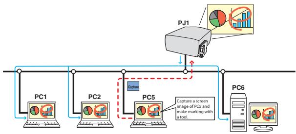
Real Time Capture function (p.72)
To display the screen image of the computer by the projector through the network in real time.

Network Communication function (p.77)
To communicate by sharing the captured image of a computer with multiple computers and a projector. User can draw the text and figure on the captured image by using a drawing tool.
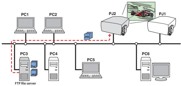
Network Viewer function (p.87)
To acquire the JPEG image data from the file servers placed in the network and project them by the projector.
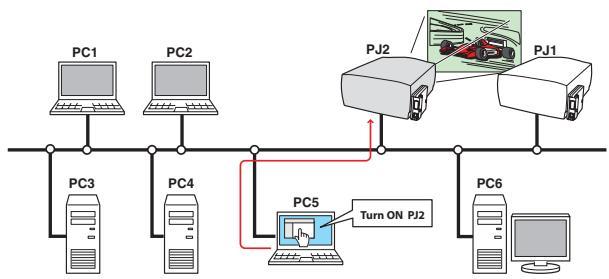
Web Management function (p.45)
With this function, you can monitor projector functions such as power status, lamp status, input mode, signal condition, lamp-use time, etc. through the network by using the web browser installed on your computer.
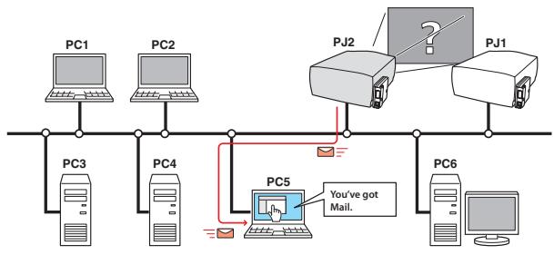
E-Mail Alert function (p.38)
The projector (Network Unit) sends messages to the registered e-mail addresses when a lamp abnormality or power failure occurs with the projector. This message describes how to solve the cause of the problems. You can take efficient action for quick recovery.
PJ Camera Viewer function (refer to the separated booklet)
By using the supplied camera, PJ Camera Viewer takes pictures of the projected images of the projector located on the remote places, and stores pictures into your computer via the network.
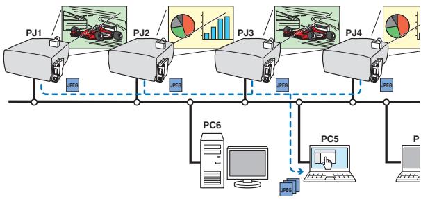
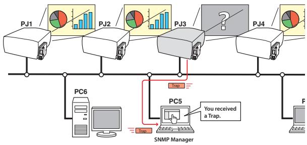
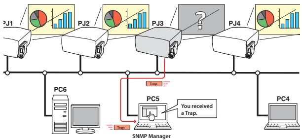
SNMP Agent function (p.42)
To send the information of the projector to the SNMP manager. Enables you to manage the projector condition with the supplied SNMP manager software.
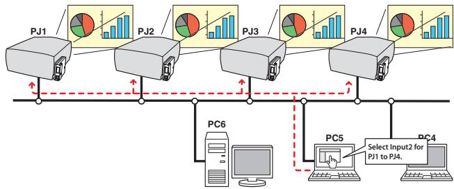
Multi-control function (p.62)
A single computer can control and set up the multiple projectors at the same time.
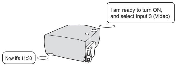
Automatic On/Off using Clock function (E5 p.57)
Automatically turn on or off the projectors at specified date/day and time by using the clock function.
SNMP Manager function (refer to the separated booklet)
A function to manage the condition of projectors in the network by using the SNMP protocol. The managing computer needs to provide an SNMP managing software. Refer to the owner's manual of the "PJ Network Manager" supplied separately for further details.
Operating environment of PJ-Net Organizer
To perform the managing and setting of the projector by using this product, the environment described below is required.
| Standard mode | ||
| Operating System | Windows 98, Windows Me, Windows NT4.0SP6 Windows 2000, Windows XP | |
| Computer environment | Recommended CPU | Higher than Pentium III 900MHz |
| Memory | 64MB (Minimum)/ 128MB or more(Recommended) 128MB or more for WindowsXP | |
| HDD free area | 100MB or more | |
| Drive equipment | CD-ROM drive | |
| Display setting of computer | Support one of following resolutions; VGA (640 x 480), SVGA(800 x 600), XGA(1,024 x 768) Number of colors: Either of 16 bit (65,536 color 24/32 bit (16,77 million colors)) | |
| Network card | The computer must provide a 10Base-T or 100Base-TX network card. | |
| Web Browser* | Internet Explorer version 5.0, 5.5 or 6.0 Netscape Navigator version6.2, 7.0 or 7.1 * Used to control and set up the projector. The layout of pages in the browser may slightly differ from each type of application or operating system you use. | |
| Plug-Ins | Adobe Flash Player version 6,0,79,0(6.0r79) or later | |
| Internet Mailer* | - Microsoft Outlook - Microsoft Outlook Express - Netscape Mail * Required the internet e-mail application software to receive an e-mail alert sent from this product. If you do not use the function E-mail Alert, this application is not required. | |
| FTP Service * | - FTP server (Windows 2000 Professional or Windows XP Professional) * The FTP service provided with the Windows 2000 Professional or Windows XP Professional is required when using the Network Viewer function. | |
- For the operating environment of PJ Network Manager and PJ Camera Viewer, refer to each owner's manual in the document CD-ROM.
PDA restriction
The PDA can be used for the Light mode*1 only. The operating system of the PDA is PocketPC2002 or higher. The version of the Adobe Flash Player is 6,0,81,0 or higher.
*1 The "Light Mode" and "Standard Mode" will be explained on item "Display Mode" (p.30-32)
The limitation\*1 of connection between this product and hub or computer
Suitable LAN cables are limited by length and type as follows;
| Connection | Type of usable LAN cable | Maximum length |
| Network Unit - Hub | UTP Straight Cable with category 3 or 5 *2 | 100m |
| Network Unit - Computer | UTP Cross Cable with category 3 or 5*2 | 100m |
1 There may be other limitations depending on your network environment or LAN specification. Please consult your network administrator for further details.
2 Category of LAN cable indicates the cable quality. Normally, a cable with category 3 or 5 is used for 10Base-T network, and a cable with category 5 is used for 100Base-TX network.
Before use
Package contains
The package contains following items. Check each item as you unpack the package. If you have any of the following items missing, contact the sales dealer.
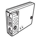
Network unit
1 piece

Quick Setup Guide English/Japanese
1 piece

Software CD-ROM
1 piece
Network Viewer & Capture 3 softwarePJ Network Manager software

Document CD-ROM
1 piece
PJ-Net Organizer Owner's Manual
PJ Network Manager Owner's manual
PJ Camera Viewer Owner's manual
Following contents are required to use the PJ Camera Viewer function.
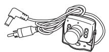
Network Camera
1 piece
Camera Packaging box


Software CD-ROM
PJ Camera Viewer software
1 piece
Camera mounting tool set
Hook and loop fastener (big) 1 piece
Hook and loop fastener (small) 1 piece
Cable fixer 1 piece
Ferrite core 1 piece
Double-sided adhesive tape* 1 piece
Safety rope* 1 piece
- For use of the double-sided adhesive tape and the safety rope, refer to the caution cards.
Notice
Expression/Abbreviation
The word "projector" found in this manual means "projector provided with Network unit" unless otherwise noted.
The OS of the computer and the Web browser described in this manual is Windows XP Professional and Internet Explorer 6.0. In case of another OS or Web browser, some instruction procedures may differ from the actual operation depending on your computer environment.
Use of this manual
This manual does not provide the description of basic operation and functions for computer, web browser, projector and network. For instructions about each piece of equipment or application software, please refer to the respective booklet.
Trademarks
Ethernet is a registered trademark of Xerox Corporation. Microsoft, Windows, Windows NT are registered trademarks of Microsoft Corporation. Internet Explorer is a registered trademark of Microsoft Corporation. Netscape Navigator and Netscape Communicator are trademarks or registered trademarks of Netscape Communications Corporation. JavaScript is a registered trademark of Sun Microsystems, Inc. PJLink is a registered trademark of JBMIA (Japan Business Machine and Information System Industries Association).
Other product or brand names in this manual are registered trademarks or trademarks of their respective owners.
- Unauthorized use of a part or whole of the contents in this manual is prohibited.
- The contents of this manual are subject to change without notice.
Chapter 2
Installation
2
Describes how to install the network unit and software, and configure the network.
Flow of installation
The following are instructions for attaching this product to the projector and connecting it to the network. Please review the entire procedure to become familiar with it.
1 Function of the network unit (p.17)
Explains the name and functions of each part of the network unit.
2 Installation and network configuration (p.18-24)
1 Mount this product onto the projector.
2 Connect the LAN cable and join it to the network.
3 Configure the network of the network unit.
4 Set the Network PIN code.
3 Installation of the software (p.25-27)
Explains how to install the software Network Viewer & Capture 3 into your computer.
Set up is complete
The preparation is completed to control the projector connected to the network. At next step, set up and control the projector via the network by using the web browser installed on your computer. Please see chapter 3 "Basic setting and operation". (p.29)
For the installing the camera and PJ Camera Viewer and operating instructions, refer to the separated owner's manual of PJ Camera Viewer.
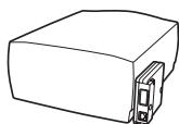
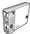
[1] Name and function of each part
![SANYO PLC-XT35 - [1] Name and function of each part - 1](/content/2025/01/96763/images/06b1754895ad83d56359fdc738e65f2eb1435baedf0bf60bbc07bc7d2901827f.jpg)
![SANYO PLC-XT35 - [1] Name and function of each part - 2](/content/2025/01/96763/images/30252e4b4a116a139f35ce884fbd2be4626f7d02090642d5a2b71622c8540ed8.jpg)
[2] Installation and network configuration
Mounting
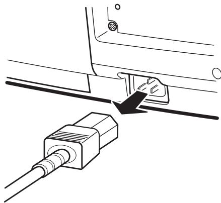
1 Disconnect the AC plug from the projector.
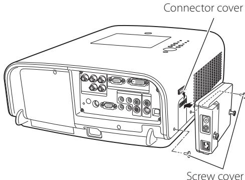
2 Remove the connector cover and screw covers (2 pieces) from the projector and insert plug on this product to the option connector.
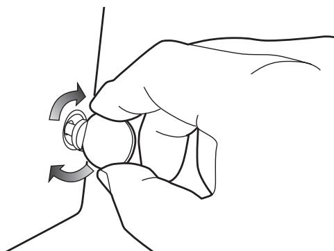
3 Tighten two screws by using a coin etc.
CAution
AC cord must be disconnected when mounting or removing this product otherwise it may damage the product.
Do not install multiple network units into a projector otherwise it may damage the product.
Connect the AC cord after connecting the LAN cable and computer.
Connection of LAN cable
To connect to the network, it is required to use the UTP (Unshielded Twisted Pair) straight cable with RJ-45 plug. There are two different types of cables depending on whether the network is constructed with 10Base-T or 100Base-TX. Prepare the Hub (10Base-T or 100Base-TX) to distribute the network cable if required.
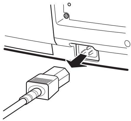
1 Disconnect the AC plug from the projector.
2 Connect the UTP straight cable to the LAN port on the network unit.
3 Connect the UTP straight cable to the hub.
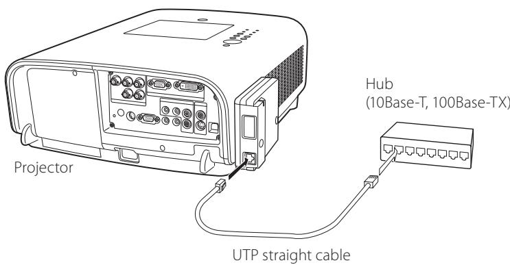
Use the UTP cross cable when you connect the computer and projector directly not using the hub.
When you connect the projector into the 10Base-T network, use cable with category 3 or 5. When you connect the projector into the 100Base-TX network, use cable with category 5.
The length of cable between hub and projector should be less than 100m
Network configuration
Confirmation of the network menu
When installing this product to the projector, the network on-screen menu items for this product are activated automatically. If not activated, the product may not have been installed correctly. Please check item "Mounting" (p.18).
Configure the network
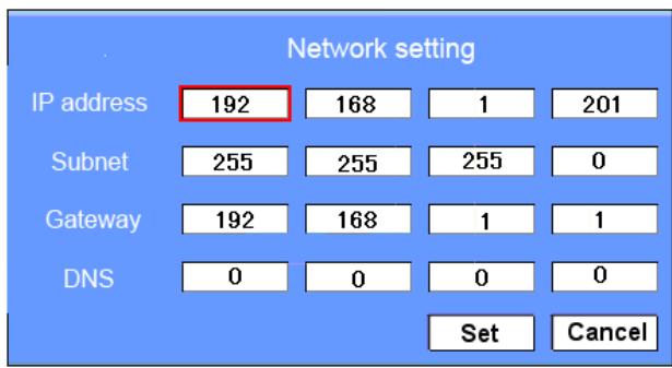
Before performing the network configuration, prepare network address numbers (IP Address, Subnet Mask, Default Gateway, DNS) assigned to the projector. Ask your network administrator for the network address.
For example, the case where the following network address is set up is explained.
| IP Address | : 192.168.1.201 |
| Subnet Mask | : 255.255.255.0 |
| Default Gateway | : 192.168.1.1 |
| DNS | : 0.0.0.0 |
The default network configuration is set as follows.
| IP Address | : 192.168.0.2 |
| Subnet Mask | : 255.255.255.0 |
| Default Gateway | : 0.0.0.0 |
| DNS | : 0.0.0.0 |
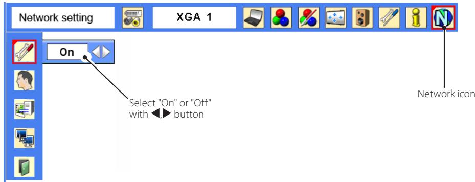
1 Selection of network menu
Turn on the projector and display the menu on the screen. Select network icon from the main menu and then press SELECT button once. Check that the mode is "On". If not, change mode to "On" using the point buttons (▲,▶).
2 Configuration for IP Address/ Sub net/Gateway\*1/DNS\*2
Press SELECT button again. The following network setting pallet appears on the screen. Enter the specified network addresses.
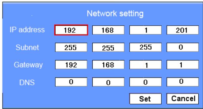
The red frame moves sequentially left or right with button. The number up or down with button.
How to enter the numbers
There are 2 ways to enter the numbers, one is by using the point buttons (▼▲) on the remote control or on the projector, the other is by using the 10-key buttons on the remote control. For further information see "How to enter the numbers with the remote control 10-key buttons" (p.23).
3 Fixing the network configuration
After completing the entering of address, select "Set" and press SELECT button. The network unit starts re-booting and displays message "Please wait..." on the screen until the re-booting is complete. Do not disconnect the AC
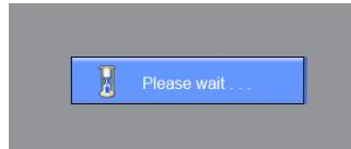
cord during this period. After that the network setting pallet will disappear on the screen.
Completing of installation
Now the installation is complete. The IP address of this projector is set to "192.168.1.201".
Item Description
IP address.......Sets IP address of the projector
Sub net.... Sets Subnet mask. Normally sets 255.255.255.0
Gateway*1....Sets IP address of the default gateway (Router)
DNS*2 .......Sets IP address of the DNS server. Must be set when using the e-mail function
Refer to the projector's owner's manual for operation of the projector.
Network PIN code setting
The Network PIN code can be set to restrict access to the setting page of the projector using the web browser.
Default Network PIN code [0000] means no Network PIN code is set.
1 Displaying Network PIN code menu
Select network menu and then select "Network PIN code" sub menu. Press SELECT button twice to display the Network PIN code entry pallet.
- The number on the pallet is the current Network PIN code.
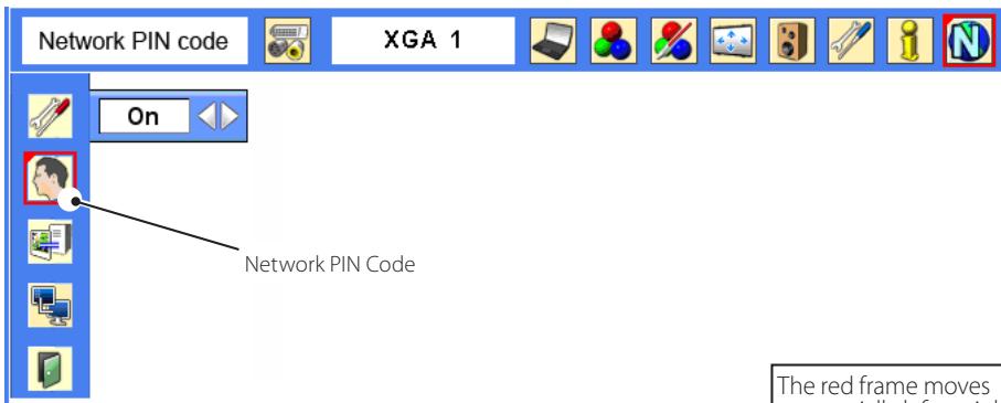
2 Entering the Network PIN code
To enter the Network PIN code, use point buttons (▲,▼,▲▶) on the projector or the remote control.
3 Fixing the Network PIN code
After entering a 4-digit number, select "Set" by using point buttons (, ) and then press SELECT button.
The red frame moves sequentially left or right with button. The number up or down with button.
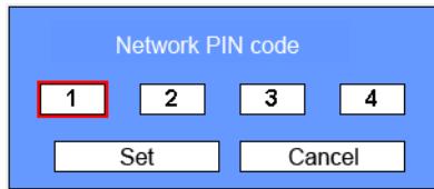
The remote control 10-key buttons can be used for entering the Network PIN code. See item "How to enter the numbers with the remote control 10-key buttons" (Eg 23)
It is recommended to set up the Network PIN code when you connect the projector to the network. This setting is carried out through the projector's menu and also it can be set through the network using the web browser. For further information, refer to item "Initial Setting/Network PIN code setting" (p.35).
Valid characters for the Network PIN code are only numbers 0 to 9. The number "0000" means no Network PIN code is set.
This Network PIN code is not to restrict the use of the projector. This Network PIN code is to set the security against the use of the projector through the network.
How to enter the numbers with the remote control 10-key buttons
During the network address input mode or the network PIN code input mode, some of the buttons on the remote control are operate as the 10-key input buttons.
1 Select a column with a red frame by using the point buttons or ▷.
2 Press 0 to 9 key assigned to the buttons to enter the numbers..
*To change the number in a column, enter the number again.
3 After entering the number in the column, press the point buttons or to move the red frame.
4 Repeat steps 1 to 3 for entering all the network address.
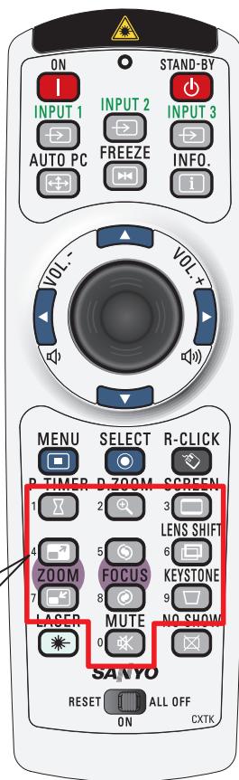
During the numbers input mode, these buttons operate as the 10 key buttons
Notice about system construction
For installation of multiple projectors into the same network with network unit.
Do not install multiple projectors with network units that have their default network settings to the same network. The use of the network units which have the default IP address set to the same network settings will cause IP addresses to collide and create a malfunction. When you install multiple projectors into the same network, configure the network with the following steps.
- Change the IP address from the default IP address. To change the IP address, use the network setting menu on the projector. Please see item "Network configuration" for further information (p.20).
- Make sure that there is no network equipment set with the same IP address in the network before connecting to the network.
- When installing other projectors, follow the above steps to change the IP address and connect to the network.
In case of installing the projector with network unit into the network constructed with the DHCP/BOOTP server.
This network unit does not support the DHCP/BOOTP server. The static IP address must be manually configured. To use this product in this network environment, set it up so that the DHCP/BOOTP server does not assign the IP address configured to this product for another device on the network. Please consult your network administrator for further information.
[3] Installing the software
It is required to install the software into your computer to use the Network Capture function and Network Viewer function. Please install the software as follows.
Note: To install the software into the computer with Windows 2000, Windows XP or Windows NT, you should logon as administrator. Before installation, make sure that the other applications are closed, otherwise proper installation cannot be made.
Network Viewer & Capture 3 installation
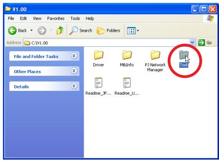
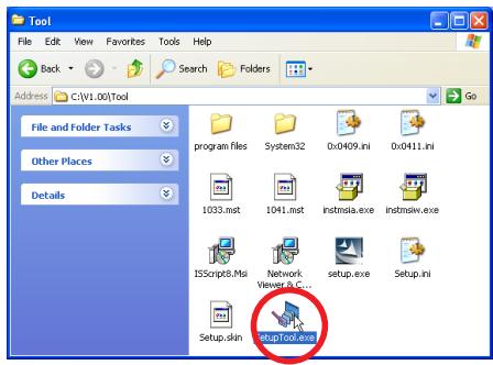
1 Set the supplied Network Viewer & Capture 3 CD-ROM into the CD-ROM drive of your computer. Double click SetupTool.exe icon in the "Tool" folder in the CD-ROM.
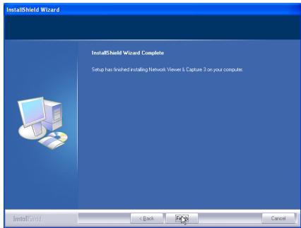
2 Select "English [United States]" from the pull-down menu on the "Choose Setup Language" window and click OK button to start installing and then follow the installation wizards.
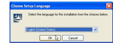
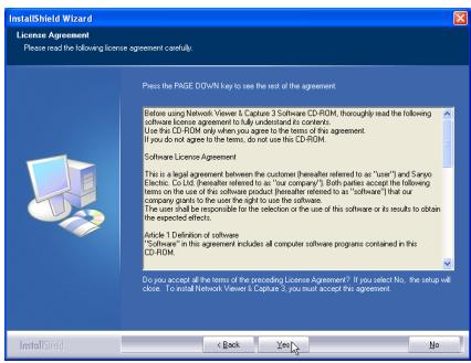
As the "License Agreement" will appear, read contents carefully and click Yes button if you agree to the license agreement to proceed with installing.
Installed software
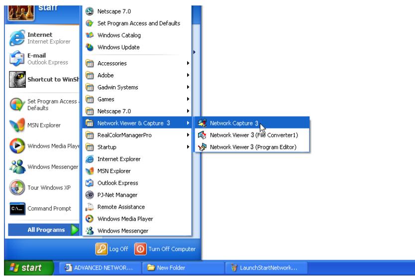
The following 3 software are installed on your computer.
Network Capture 3:
Capture the displayed image of the computer and serve it to the projector via the network.
This software is registered into "startup folder" of the computer and the capture icon stays on the task bar after booting the computer.

- Network Viewer 3 (File Converter 1):
Converts to the JPEG* data format which can be projected with the projector from the JPEG, bitmap and Power Point files.
Network Viewer 3 (Program Editor):
This is a tool to make the program which has a function to specify and order the projecting JPEG image data stored in the file servers.
- To uninstall these software, use "Add/Remove Program" from the control panel.
*1 This product supports the JPEG image format. This file is needed to convert to the optimized JPEG file by using the File Converter 1 software previously. Refer to the item "Creating the available data [Network Viewer 3]"(p.88) about data converting for the projection.
File Converter 2 Installation
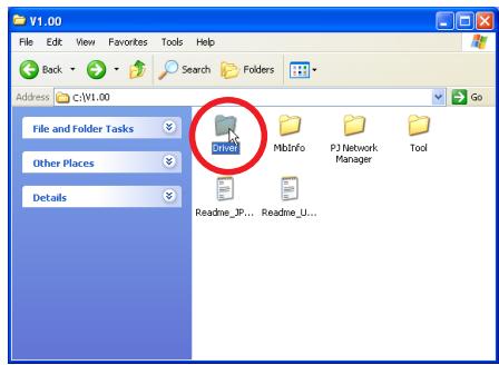
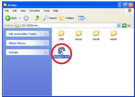
1 Set the supplied Network Viewer & Capture 3 CD-ROM into the CD-ROM drive of your computer. Double click SetupDrv.exe icon in the "Driver" folder in the CD-ROM.
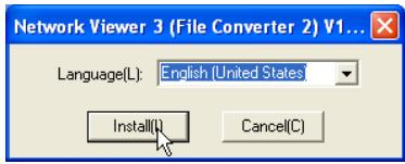
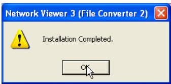
2 Select "English [United States]" from the pull-down menu on the language selection window and then click Install button to start installing.
Installed software and places
Network Viewer 3 (File Converter 2) is installed in the "Printers and Faxes" folder in the "Control Panel".
Network Viewer 3 (File Converter 2):
This is a kind of the printer driver to convert to the JPEG data optimized to project by the projector from any of the documents created by the application software.

Chapter 3
Basic Setting and Operation
Describes basic operations and settings for controlling the projector by using the web browser. It is required that computer and projector is connected to the network and the network address is properly configured.
3
Login the setting page of the projector
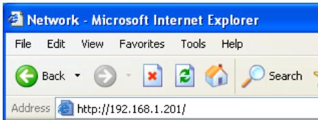
1 Enter the IP address
Launch the web browser installed in your computer, enter the IP address into the "Address" on the browser and then press "Enter" key.
Enter the address (192.168.1.201) that you configured in item "Network configura
tion" (p.20). The default IP address is [192.168.0.2].
2 Select a display mode and login
This product provides 2 types of control mode, Standard Mode and Light Mode as the below. Select a proper mode to match your PC and network environment by clicking on the text link. Once you select your desired display mode, the setting page you selected display mode will be displayed automatically from the next login. To change the display mode, click "Top" on lower-right corner of the setting page (p.31).
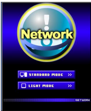
STANDARD MODE
LIGHT MODE
For computer display, displays graphical menus and settings. This mode is recommended for standard use.
Displays with 200 × 300 dots. This mode is optimized for use of the handheld computer, PDA, etc. It is also convenient if the network traffic is heavy. (This mode has some limitations on the network viewer and multi-control functions.)
If the setting page has set the password, the authentication window will appear. In this case type "user" onto the User Name text area and the login Network PIN code onto the Password text area and then click OK button.
- The entering User Name must be "user" and it can not be changed.
[Note]
When accessing the projector for the first time or the Network PIN code "0000" is set, the auto-login will be performed and the next main setting page is displayed.
![SANYO PLC-XT35 - [Note] - 1](/content/2025/01/96763/images/3955f6119ef10b85268742b02b3d814c889965a47b4cf39e04f9d8f2add187a4.jpg)
3 Display of main setting page
The following main setting page will be displayed according to your display mode selection. Perform various kinds of settings through this page. Click on the menus to display the control and setting pages.
1 Main setting page in the Standard Mode display
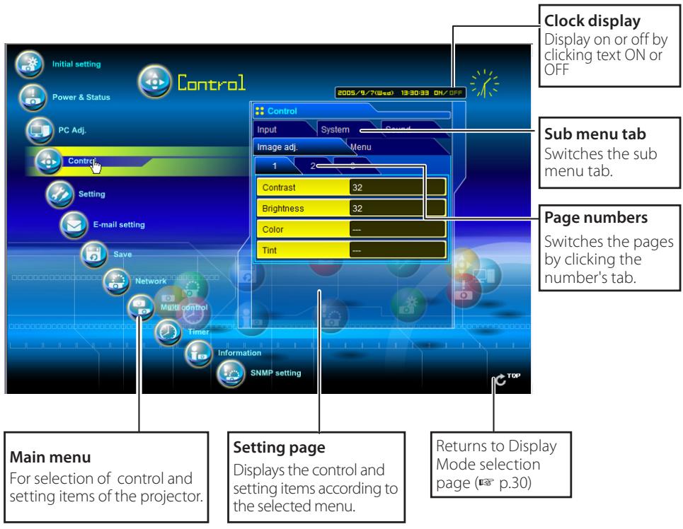
This Standard mode display is mainly used through this manual for the setting and control description.
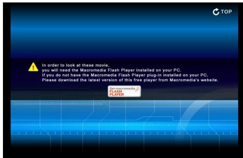
If your computer does not have the Adobe Flash Player version 6 or later, follow to the message on the control page to install the Adobe Flash Player. For further product information or installing, see the Adobe homepage.
http://www.adobe.com
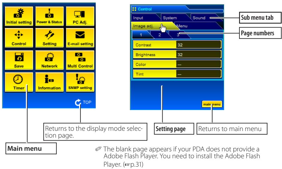
2 Main setting page in the Light Mode display
The network viewer function in the Light mode has following limitation;
- Cannot select the program or folder for the display (p.97, p.99)
Cannot check up the images in the folder or program (p.100).
How to use the setting page
To control and set up the projector, use the setting menus on the web browser. Describes the basic operation and procedures commonly used on this manual.
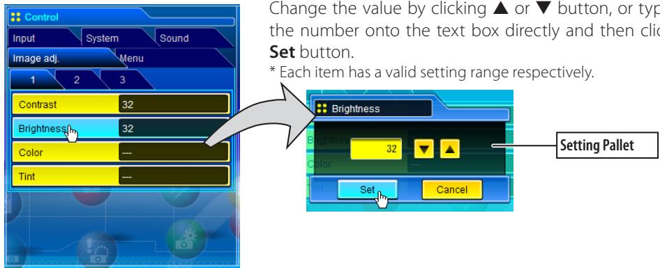
Example of the Setting Page
The value in the text box indicates current value.
Each item has a valid setting range. The setting value exceeding this becomes invalid. Some control items can not be used depending on the selecting input mode or functions of the projector you use. In this case, the values of those items are indicated with "---".
Type of the setting pallet
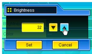
Text box setting
Enter a number or text and then click Set button.
or
Change a value with or button and then click Set button.
The value changes quickly when keeping pressing or button.
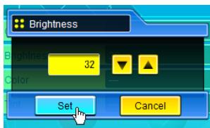
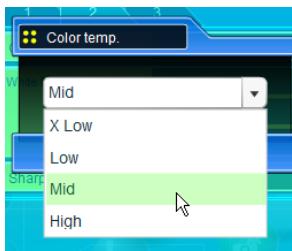
Pull-down menu setting
Select an item with pull-down menu button and then click Set button.
or
Select an item by clicking or button.

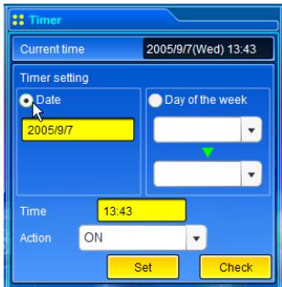
Radio button setting
Select an item by selecting a radio button
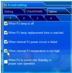
Check box setting
Select items by ticking on check boxes.

Initial setting
After installing this product to the projector, perform the following basic initial setting.
Click Initial setting on the main menu to display the initial setting page.
The model name of the projector on which this product is mounted is displayed on the page.
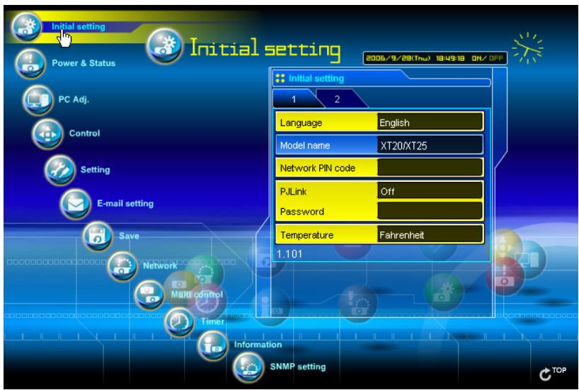
Item
Description
Language......Switches display language on the setting page. English or Japanese.
Model name....Indicates the model name of the projector provided with the network unit
Network PIN code....Sets the Network PIN code to login the setting page (E8 p.35)
PJLink.........Switches PJLink password authentication on or off (p.35)
Password............Password for PJLink function
Temperature......Switches display temperature unit Centigrade or Fahrenheit
△Caution
Use of Battery
This product provides a lithium battery. When the battery runs down, the clock and timer functions do not operate properly. Contact your local dealer for the replacement of battery. The replacement must be carried out by a qualified service personnel.
Network PIN code setting
This is to set the Network PIN code to restrict the access from an unauthorized person through the network.
Enter a 4-digit number as the Network PIN code onto the text box and click Set button.
The network unit begins restarting and it takes about 20 seconds. Close (Quit) the web browser and access to the login
page again in 20 seconds. This is to perform the login authentication firmly.
The default Network PIN code [0000] means no Network PIN code is set.
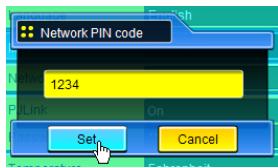
When you connect the projector with this product to the network, it is recommended to set a new Network PIN code. Only a four-digit number is valid for the Network PIN code.
If you forget the Network PIN code to the projector, you can check it by selecting "Network PIN code" sub menu from "Network" menu on the projector. For further information, please see item "Network PIN code setting" (p. 22).
PJLink and password setting
This is to set the PJLink password authentication on or off. If set "On" with the PJLink pull-down menu, the password must be required. Enter a password* onto the text box and click Set button.
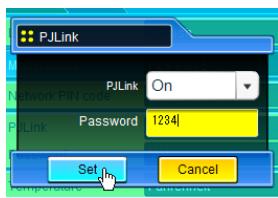
1 to 32 alphanumeric characters can be used for the password.
What's PJLink?
The projectors equipped with PJLink function can be used together on the same network, regardless of model or brand, for centralized control and monitoring. This standard was established by the Japan Business Machine and Information System Industries Association (JBMIA).
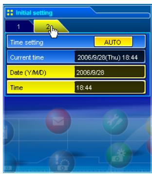
Item Description
Time setting....When clicking AUTO button, the date and time set on your computer are set to the network unit
Current time.....Indicates current date and time set on the network unit
Date.... Sets date in manual
Time.... Sets time in manual
Date and time setting
Auto setting
Click AUTO button on the page, the date and time set on your computer are set to the network unit.
Note:
Confirm that your computer has a correct clock time before performing the auto time setting.
Manual setting
Click item Date or Time and enter date or time on the input box with adequate format.
Date is in year/month/day format.
ex. 2006/04/25
Time is in 24-hour:minute format.
ex. 18:30
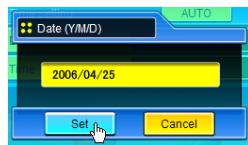
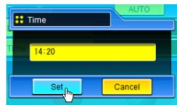

Network configuration
Click Network on the main menu. The following setting page is displayed. The IP Address, Subnet Mask, Default Gateway, DNS (Domain Name Server) and projector name are set up on this Setting sub menu.
The IP address and Subnet Mask have been configured already in chapter "Installation". If you want to change them or configure default gateway or DNS, perform them in this page. If you change them, the network unit begins restarting and it takes about 20 seconds. Close (Quit) the web browser and access to the login page again in 20 seconds.
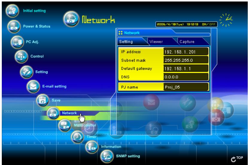
Item Description
IP address.......Sets IP address of the projector
Subnet mask....Sets Subnet mask. Normally sets 255.255.255.0
Default gateway*1....Sets IP address of the default gateway (Router)
DNS*2 ........ Sets IP address of the DNS server. Must be set when using the e-mail function
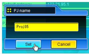
PJ name*3....Sets name of the projector. (64 characters maximum)
You must use the number specified by your administrator. The address must be entered as a group with four numbers split by a dot like [192.168.001.101].
1 Set [0.0.0.0] if the network does not provide the gateway (router).
2 Set [0.0.0.0] if you do not use the function E-Mail alert.
3 If you use the DNS server, register the host name registered to the DNS server as a projector name. You can access with this projector name from any computers in your network. If you do not use the DNS server, access with the assigned IP address to the projector.
All the network setting will reset to the default when setting [0.0.0.0] of the IP Address.

E-mail setting
This product has an E-mail function which can send an alert message to users or an administrator if it detects an abnormality on the projector or run out of the life span of the lamp. Click E-mail setting on the main
menu and follow the below steps.
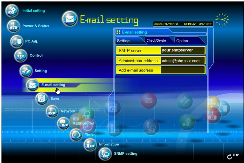
Item Description
SMTP server*1....Sets server name or IP address of the SMTP server
Administrator
address.... Sets e-mail address of administrator
Add e-mail
address.... Sets e-mail address of the user to send mail when the projector has an abnormality.
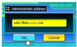
1 Setting SMTP server and administrator address
Set the server name or IP address of the SMTP server*1 and administrator address. The administrator address is set to "Reply-To" address of the message sent from the projector.
*1 The SMTP server is a server for sending E-Mail. Please contact your network administrator to have this SMTP server address.
If the network unit sends an alert message due to the abnormality on the projector but the SMTP server is down in some other reason, the message will not be sent. In this case, the message "Unable to connect to server." will be displayed on the setting page. To clear this message, set up SMTP server address again.
To use the E-Mail function, it must be set the DNS address on the Network setting page correctly.
You cannot use this E-mail function if the DNS server and SMTP server cannot be used in your network environment.
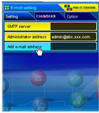
2 Registering and deleting E-mail addresses
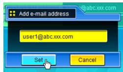
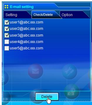
Click "Add e-mail address" and type the e-mail address onto the text box and click Set button. To check the registered addresses, click Check/Delete sub menu tab. The addresses are listed as the figure on the right.
Up to 10 E-mail addresses can be registered.
To delete the registered addresses, check the address you want to delete and click Delete button.
3 Option selection for sending alert mail
Click Option sub menu tab. Check the condition items under which alert mail will be sent and click Set button.
Please refer to item "Examples :Type and contents of alert mail" described on the next page.
Check/Delete
Option
[1]
When PJ lamp is off.
When PJ lamp replace time is reached.
When internal PJ power circuit is failed.
- When internal PJ temperature is too high.
- When PJ is turned into Standby in proper user operation.
[2]
When Power management function turns PJ lamp off.
When the signal is interrupted.
When Auto Play is failed.
[3]
When accumulated filter use time reaches [ ] hours.
When filter is clogged.
[4]
When lamp Corres. Value reaches [ ] hours. Attached message
![SANYO PLC-XT35 - [4] - 1](/content/2025/01/96763/images/a02747fe10f5867101847c450d4f40ac0314c301d44405e9c9c55c502fc928d2.jpg)
If condition "When Auto Play is failed" is checked, the trap is sent when occurring the error during the auto display operation using with the network viewer function (p.98). For further information of the error, refer to item "Auto Display setting and control page [3]"((p.101).
The length of message should be less than 256 characters.
Up to 99,999 hours can be set for use time.
Examples: Type and contents of alert mail
When the projector has an abnormality, the following alert messages are sent to the registered E-mail address according to your selected condition. Administrator or user can take an efficient action quickly by receiving this message. This is very useful to maintain and service the projector.
The following are examples of received messages.
- When internal PJ temperature is too high:
TITLE: Message from projector
10-03-2005 00:59
Projector Model Name: model name
TCP/IP: 192.168.1.201 Projector Name: Proj05
It sends you following message.
*The Projector lamp is turned off, because internal Projector temperature is too high.
Wait for Temperature Warning Indicator turned off, and then turn the Projector on again. If the Indicator continues flashing, check the air filter for dust accumulation.
[A] 81.5 degrees fahrenheit [B] 134 degrees fahrenheit [C] 95.6 degrees fahrenheit
Temperature of Sensor B is too high.
The network unit let users know the information which thermal sensor [A], [B] or [C] inside the projector detected the abnormal temperature risen and so the projector was turned off. Please refer to item "Power control and status check" (p.46) for the location of the sensors and each temperature. Also see the owner's manual of the projector for further details.
- When internal PJ power circuit is failed:
TITLE: Message from projector
10-03-2005 00:59
Projector Model Name: model name
TCP/IP: 192.168.1.201 Projector Name: Proj05
It sends you following message.
*The Projector lamp is turned off, because Projector power circuit is failed.
Unplug the Projector from AC outlet and ask servicing to qualified service personnel.
AV, -5V
AV, S5V
PJNET, S5V
ANALOG,6V
中 中 中
The projector lamp was turned off, because the projector power circuit failed.
Unplug the projector from AC outlet and ask servicing to a qualified service personnel with the error information.
- When PJ lamp replacement time is reached:
TITLE: Message from projector
10-03-2005 00:59
Projector Model Name: model name
TCP/IP: 192.168.1.201 Projector Name: Proj05
It sends you following message.
*The PJ lamp replace time is reached.
Replace it with a new lamp immediately and reset the lamp counter. If the projector is used without resetting the lamp counter, the alert mail is sent to users in every power-on of the projector. This alert mail will not be sent when unchecking the mail sending condition "When PJ lamp replacement time is reached".
- When lamp corres. value reaches preselect use time:
TITLE: Message from projector
10-03-2005 00:59
Projector Model Name: model name
TCP/IP: 192.168.1.201 Projector Name: Proj05
It sends you following message.
*The accumulated lamp use time has reached 1200 hours.
Prepare for the lamp replacement.
Free messages
The network unit sends a free message when the lamp use time (Corresponding value) reaches the preselected lamp use time. It can be used for preparation of the lamp replacement and the maintenance required.

SNMP setting
This product provides a SNMP (Simple Network Management Protocol) agent function. The SNMP consists of a manager and agents. The group which communicates information each other with SNMP is called
"Community". There are two access modes in a community, Refer (read only) and Set (read-write). This product allows to use Refer (read only) only. The SNMP message informs the projector status called "Trap" to an administrator. Click SNMP setting on the main menu and set up each item.
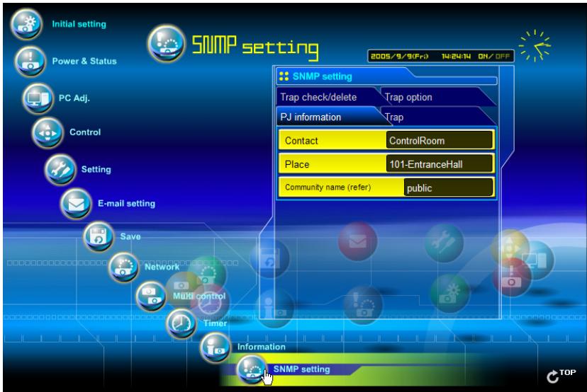
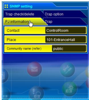
PJ information
Item
Description
Contact......................................Enter user name of the projector etc. (optional)
Place......................................Enter place of the projector (optional)
Community
name(refer)......Enter community name (read only). Default name is "public".

The SNMP agent provided with this product is based upon MIB-2 defined by RFC1213. For private MIB information, refer to file "Mibinfo/10PjNetPlus2.mib" in the CD-ROM.
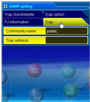
Trap
Item
Description
Community name....Enter community name to send "Trap". Default name is "public".
Trap address.......Enter IP address of the SNMP manager computer to receive "Trap".
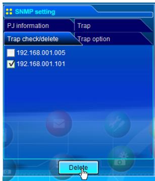
Trap check/delete
Check and delete the trap address
Checking the registered trap address and deleting the address.
To delete the address, tick check box in front of the IP address and click Delete button.
Up to 10 trap addresses can be registered.
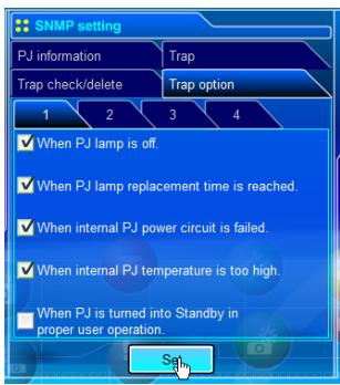
Trap option
Trap option setting
Tick check boxes in front of the condition item to send the trap.
Click Set button if you tick or un-tick the check box on a page.
[1]
When PJ lamp is off.
- When PJ lamp replacement time is reached.
When internal PJ power circuit is failed.
When internal PJ temperature is too high.
- When PJ is turned into Standby in proper user operation.
[2]
When Power management function turns PJ lamp off.
When the signal is interrupted.
When Auto Play is failed.
[3]
- When accumulated filter use time reaches [ ] hours.
When filter is clogged.
[4]
When lamp Corres. Value reaches [ ] hours.
Up to 99,999 hours can be set for the time setting.
If condition "When Auto Play is failed" is checked, the trap is sent when occurring the error during the auto display operation using with the network viewer function (p.98). For further information of the error, refer to item "Auto Display setting and control page [3]"(p.101).
Chapter 4
Controlling the Projector
Describes controlling and setting of the projector by using the web browser.
4

Power control and status check
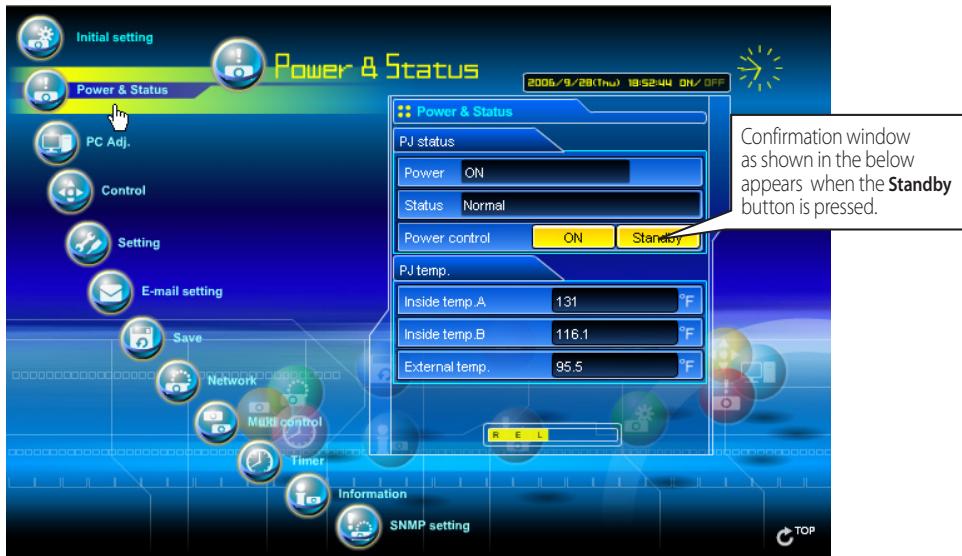
Click Power & Status on the main menu. The control page will be displayed.
By clicking ON or Standby button on the page, the power of the projector can be controlled.
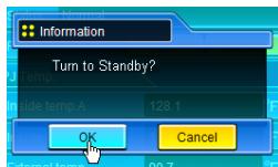
Popup confirmation window
Item
Description
PJ status
Power .....................Displays the status of the lamp. (ON, OFF, On starting up, On cooling down)
Status .....................Displays the status of the projector's power. (Refer to next page.)
Power control.....Controls the projector power by clicking the "ON" or "Standby" button.
PJ temp.
Inside temp.A .......Displays the surrounding temperature of lamp in the projector. (Sensor B)
Inside temp.B .......Displays the surrounding temperature of panel in the projector. (Sensor C)
External temp. .......Displays the surrounding temperature of the intake vent. (Sensor A)

The warning icon will appear if the temperature exceeds a specified value. Check if there is no object to obstruct the airflow around the intake or exhaust vent. It might be airfilter clogged. Clean up the airfilter.
- The temperature unit can be set either Centigrade or Fahrenheit in item "Initial setting". (p.34)
About projector condition
Status
Description
Normal…………………Projector is operating normally.
Power management under operation.. Power management is operating
Lamp failure. Lamp failure is occurring
Abnormal temperature .The temperature of the projector became too high
Cooling off due to abnormal temp. Projector detects abnormal temp. and is cooling down itself.
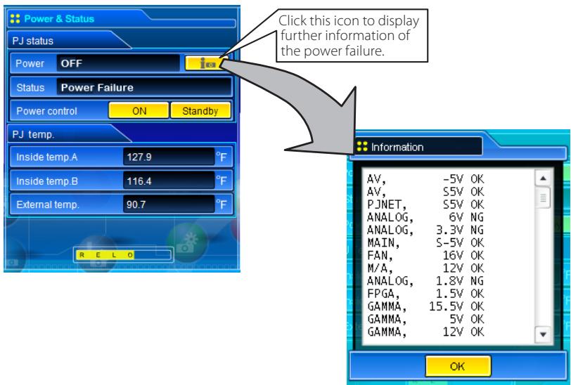
Power failure . Power failure has occurred inside the projector. Projector is turned off. Disconnect the AC cord and ask servicing to a qualified service personnel.
If the power failure occurs on the projector, "Power failure" is indicated on the status column and the information icon appears on the power column as shown below. Click this icon to display further information of the power failure.
When a security (PIN code lock) has been set on the projector, you also cannot control it through the network. To control the projector through the network temporarily, execute "PJ lock suspend" command to unlock the security. "PJ lock suspend" is on setting sub menu [3] on Setting main menu. (p.54)
The projector cannot be turned on while the projector is on cooling down.
The web browser checks and updates the projector's condition every 30 seconds automatically.

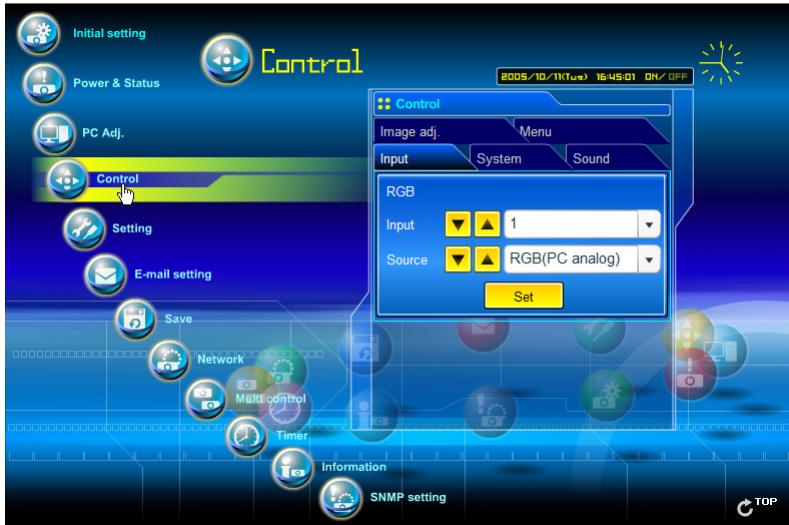
Controls
Click Control on the main menu. The setting method differs depending on the contents of the page. Click on the page number to change pages and select desired setting items.

Please see the owner's manual of the projector to have the further information of each control item.
Input
This function is to select the input mode and source mode of the projector. Click Set button after selecting the input and source mode.
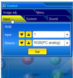
Item
Description
Input.... Selects input mode of the projector. (1 to 4)
Source.... Selects signal source of the input.
Input 1: RGB(PC analog)
RGB(Scart)
RGB(PC digital)
RGB(AV HDCP)
Input 2: RGB
Video
Component
Input 3 : Auto
Video
S-video
Input 4: Network
The control page displays valid control items depending on the selected input mode, signal or functions of the projector you use, therefore, there may be different controls between the described items and actual control items on the page display. For further information, refer to the projector's owner's manual.
When the projector is in standby, only the timer on the setting menu is effective; others are inactive.
System
This function is to select the system of signal input to the projector. The available system mode are listed on the pull-down menu button according to the input signal. Select a system and then click Set button.
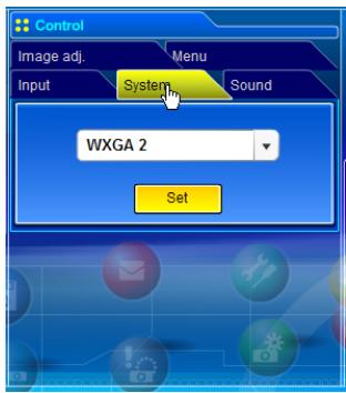
Available selection at the RGB(PC analog) input
| Item | Description |
| XGA1 | It automatically switches to the proper computer system of the input signal. |
| *The computer system modes (VGA, SVGA, XGA, SXGA, UXGA, WXGA...) which meet the input signal are listed. |
Available selection at the RGB(PC digital) input
| Item | Description |
| D-XGA.................... | It automatically switches to the proper computer system of the input signal. |
| *The computer system modes (D-VGA, D-SVGA, D-XGA. D-SXGA1...) which meet the input signal are listed. |
Available selection at the Video/S-video/Scart input
| Item | Description |
| AUTO | It automatically switches to the proper color system of the input signal. |
| * The selectable color systems are PAL, SECAM, NTSC, NTSC4.43, PAL-M and PAL-N. | |
| * AUTO is fixed at the Scart input. |
Available selection at the RGB(AV HDCP) input
| Item | Description |
| AUTO | It automatically switches to the proper scanning system of the input signal. |
| *The selectable scanning systems are D-480p, D-575p, D-720p, D-1035i and D-1080i. |
Available selection at the Y,Pb/Cb,Pr/Cr input
| Item | Description |
| AUTO....................It automatically switches to the proper scanning system of the input signal.*The selectable scanning systems are 480i, 575i, 480p, 575p, 720p, 1035i and 1080i. | |
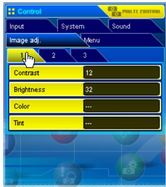
Image adjustment
This function is to adjust the projected picture image and save the image mode. To store the adjusted value, click Store button, and to load the adjusted value, click Load button.
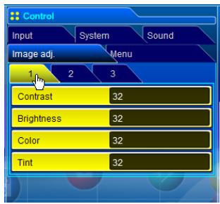
Item Description
Contrast............Adjusts picture contrast (0 63)
Brightness............Adjusts picture brightness (0~63)
Color............Adjusts picture color saturation (0 63)
Tint Adjusts picture hue (0 63)
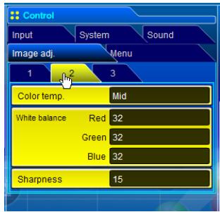
Item Description
Color Temp....Sets a color temperature mode. (X Low, Low, Mid, High, Adj.)
White Balance
Red, Green,
Blue............Adjusts each white balance respectively. (0 63)
Sharpness....Adjusts picture sharpness. (0 31)
- When changing the value of the white balance, the color temp. indicates "Adj."
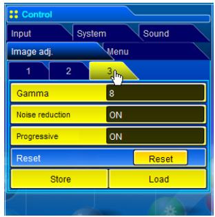
Item Description
Gamma............Adjusts brightness of darker part of the picture. (0 15)
Noise reduction...Switches noise reduction mode (OFF, L1, L2)
Progressive....Switches progressive mode (OFF, L1, L2, Film)
Reset.........Resets the Image adjustment to previous levels.
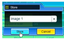
Store Stores the Image adjustment values. Select an item [Image1 - Image4] from the pull-down menu and click Store button.
Load....Loads the Image mode. Select an image mode from the pull-down menu and click Load button.There may not be available mode depending on the input mode as shown in the table left.
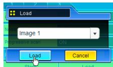
| Input source | ||
| Image mode | Video | Computer |
| Standard | ✓ | ✓ |
| Cinema | ✓ | * |
| Real | * | ✓ |
| Dynamic | ✓ | ✓ |
| Image1 - 4 | ✓ | ✓ |
The mark "√" means that the available image mode in the selected input source. The error message appears when selecting the disabled image mode indicated with "*".
Sound
This function is to adjust the sound of the projector. The values in the text box represent the current control value or status.
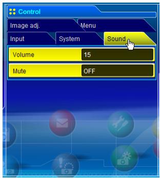
Item Description
Volume....Adjusts the sound volume from the speakers.(0 ~ 63)
Mute....Suppresses the sound. (ON, OFF)
Menu
This function is to control the On-screen menu of the projector. Switches menu on/off, moves menu selection (cursor) and executes the selected menu item.
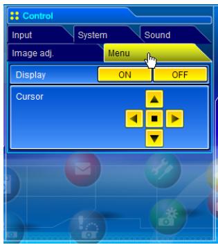
Item Description
Display.........Switches the on-screen display menu on or off by clicking ON or OFF button.
Cursor.......Moves cursor selection by clicking ▲and 7 buttons and executes the selected menu item by clicking ■ button.

PC adjustment
Click PC Adj. on the main menu. This function is to adjust the signal from the computer connected to the projector to obtain the proper picture image on the screen.
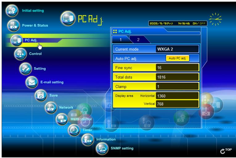
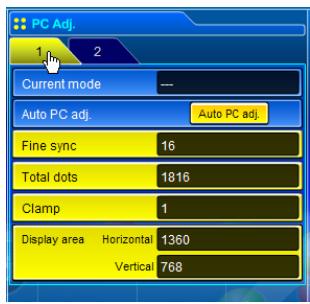
Item Description
Current mode....Displays a current mode like VGA, SVGA, XGA. SXGA, UXGA, WXGA, etc. or MODE1 - MODE10, EXT11 -EXT50 which are the customized mode created by using the "Mode Store" function described below.EXT51 -EXT60 represents mode Totalsave 1 -Totalsave10 used in the item "Save" (p.55).
Auto PC adj....Performs automatic adjustment.
Fine sync....Performs Fine Sync adjustment.(0~31)
Total dots....Adjust the number of total dots in the horizontal period.
Clamp.. Adjusts the phase of the clamp. (1 255)
Display area
Horizontal....Adjusts the image area horizontally.
Vertical ............Adjusts the image area vertically.
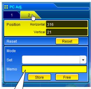
Item Description
Position
Horizontal....Adjusts the horizontal position of the screen.
Vertical............Adjusts the vertical position of the screen.
Reset......Resets the PC adjustments to the previous levels.
Mode Store.....Stores the PC adjustment values. Select a mode no.[Mode1 - Mode10, ExMode11 - ExMode50] from the pull-down menu.
Mode Free.....Clear the PC adjustment values. Select a mode no.[Mode1-Mode10, ExMode11 - ExMode50] from the pull-down menu.

Setting up the projector
Click Setting on the main menu. This function is to set up the projector. Select the sub menu [Screen setting] or [Setting] and then set up each setting.
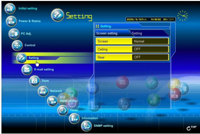
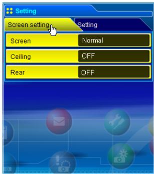
Item Description
Screen.........Switches the screen mode. (Normal, Wide, True, Full screen, Custom*) There may not be available mode depending on the input mode as shown in the table below.
Ceiling.... Sets the image top/bottom and left/right reversed. (ON, OFF)
Rear.... Sets the image left/right reversed. (ON, OFF)
| Input source Screen mode Video Computer | ||
| Normal | ✓ | ✓ |
| Wide | ✓ | ✓ |
| True | * | ✓ |
| Full screen | * | ✓ |
| Custom*1 | ✓ | ✓ |
The mark "✔" means that the available screen mode in the selected input source system. The error message appears when selecting the disabled screen mode indicated with "*".
- This item may appear only if the projector supports.

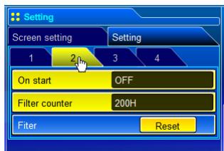
| Item | Description |
| Logo | Sets on or off the logo display on the screen during the startup. (Default, User, OFF) |
| Background | Sets screen background to blue when no signal input. (Blue, User, Black) |
| Display | Switches on or off the on-screen menu display on the screen.(OFF, CountdownOff, ON) |
| Freeze | Sets the image to freeze mode.(ON, OFF) |
| Power management | Sets into the selected power management mode (OFF, Ready, Shutdown) if the input signal is interrupted and no control key is pressed for the specified period of time. *The specified time can be set 1 to 30 min. |
| Item | Description |
| On start | Sets the power-on mode when connecting the AC cord to the outlet. (ON, OFF) |
| Filter counter | Sets the time to indicate the filter replacement message on the screen. (Off, 100H, 200H, 300H) |
| Filter | Click Reset button to reset the filter use time. |
| Item | Description |
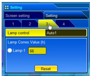
Lamp control......Selects lamp control mode. (Auto1, Auto2, High, Normal, Eco, Eco1, Eco2, etc.) * The available items depend on the projectors.
Lamp
Corres. Value(h) Displays the lamp use time (Corresponding value). Reset the time after lamp replacement.
Lamp Corres. Value Reset
-
Select a Lamp-1 radio button and then click Reset button.
-
Click OK button to execute the reset.
Item Description
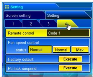
Remote control....Sets the remote control ID.(Code 1 - Code 8)
Fan speed control.... Sets the fan control speed. (Normal, Max)
Status ....Indicates the current fan mode.
Factory default.... Sets all of the projector control items to the factory default setting except the following items. Lamp Corres. Value, PJ time, Network PIN code, Network setting
- This function is not effective for the settings of the network unit, Network address settings, e-mail settings, etc.
PI lock suspend......When the projector has a security of PIN code lock, disable this function temporarily by pressing Execute button.
Setting procedure
- Turn off the projector, disconnect AC cord from the outlet and then connect AC cord again.
- Access this page with the web browser,
- Click Execute button on the PJ lock suspend.
- This function is disabled after the projector turns on.

Save the controls and settings
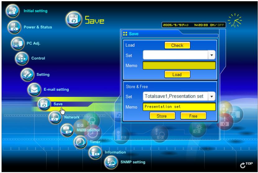
This page is to save and load the controls and settings of the projector in the block. The storable items are "PC adjustment", "Control" and "Setting".
Store/free the settings
1 Click Save menu on the main menu.
2 Select a set number (Totalsave1 to Totalsave10) you intend to store current settings with the pull-down menu button of the item Store & Free. Name this set number onto the Memo text area.
- Up to 18 characters can be used for the Memo.
3 Click Store button to store the current setting and name into the selected set number.
To remove the saved setting, select the set number with pull-down menu button and then click Free button.
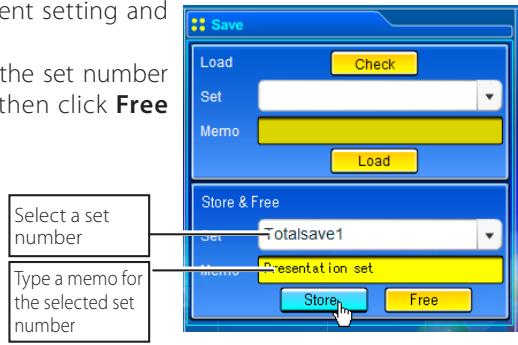
You can store up to 10 (Totalsave1 to Totalsave10) sets of settings into the network unit. Totalsave1 to Totalsave10 are indicated on the item "Current mode" of the PC adjustment (p52) as the EXT51 to EXT60.
Check the saved items
Click Check button to check the current setting condition of the controls. Each item of "PC adj.", "Control" and "Setting" is displayed sequentially.
Load a control set
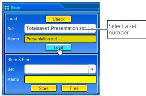
Select your desired set number (Totalsave1 to Totalsave10) with the pulldown menu button of Load Set and then click Load button. The setting values of the selected set number are applied to the current settings.
If the contents of the saved set are not matched for the inputs equipped on the projector, the invalid alert message may be displayed.

Timer setting
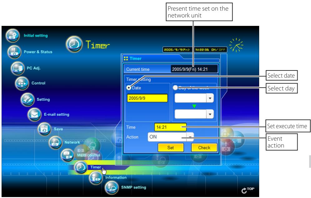
This page is to set the timer to turn the projector off or on at a programmed day/date and time. Follow the steps below for setting.
Click Timer on the main menu.
How to set the timer
1 Set a day or date
To set the timer event at same time everyday or every week,
Select day entry with radio button and then select desired days with the pull-down menu button.
The selectable days are as follows:
- Same time everyday - Every week (days from Monday to Sunday)
To set the timer event on specified date,
select date entry with radio button and then type the date with (Year/Month/Date) format.
Ex.: Type [2005/12/20] if you specify [December 20, 2005].
2 Set an execute time
Type the time with (Hour:Minute) and 24 hours format.
Ex.: Type [18:25] if you specify [PM 6 o'clock and 25 minutes].
3 Select an event action
Select an event action from the pull-down menu.
Event Action
ON.Turns on the projector
OFF.Turns off the projector
Lamp Auto1............Changes lamp mode to "Auto1"
Lamp Auto2.........Changes lamp mode to "Auto2"
Lamp High............Changes lamp mode to "High"
Lamp Normal....Changes lamp mode to "Normal"
Lamp Eco............Changes lamp mode to "Eco"
Lamp Eco1 ....Changes lamp mode to "Eco1"
Lamp Eco2.......Changes lamp mode to "Eco2"
*Available events depend on the projector function.
4 Register an event
Click Set button to register the set timer event. Repeat steps 1 to 4 for another timer event setting.
Check the timer events
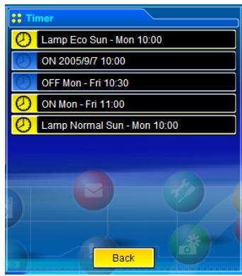
To check the set timer events, click Check button. The timer events are listed. The event with blue background color represents the timer-OFF event.
Change the event mode
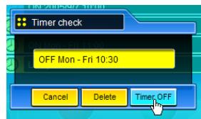
On the event list appearing by clicking Check button, click on the event you want to delete, disable or enable. Click Cancel, Delete, Timer ON or Timer OFF button on the popup pallet.
Button Operation
Cancel.Cancels the setting
Delete.......Deletes the timer event
Timer OFF.........Disable the timer event temporarily
Timer ON.....Enable the timer event
Notes on timer setting
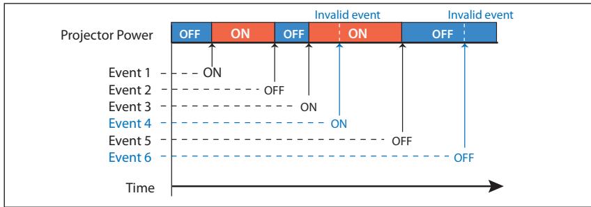
Up to 10 timer events can be registered. Timer events always operate according to the next valid event depending on the projector's power status. In the example below, event 3 turns on the projector so next event 4 (also turning on projector) will not be effective because the projector is already turned on. Similarly, when the projector is turned off by event 5, event 6 OFF will not be effective in turning it off again. But these secondary events (event 4 and event 6) will become effective if a person turns off the projector (after event 3 and before event 4) or turns on the projector (after event 5 and before event 6).
When the timer events are set at the same time, the last event set will override the previous events. For example, if there is an event like "ON at 8:00 everyday" and then new event is set like "OFF at 8:00 everyday", only the last setting event is effective.
When the timer event ON occurs during cooling down period, this is invalid event because the projector cannot be turned on during this cooling down period.

Projector information
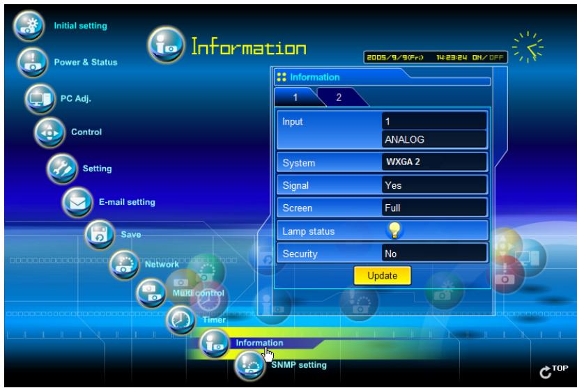
This page is to display the basic information of the projector status. Click Information on the main menu.
Items Description
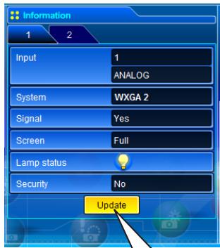
Input.................................................. Displays selected input and source.
System.........Displays selected signal system.
Signal............Input signal status (Yes, No)
Screen..................................................Displays screen mode.
Lamp status...................................Displays lamp status with an animation. Refer to the table on the next page.
Security..................................................Displays the security (PIN code lock) status (Yes, No)
Click this button to update the information
Indication of the lamp status
| Icon display/background | Status |
| White-Yellow/Blue | Lamp on (Normal) |
| White-Yellow/Red | Lamp on (Lamp is being used over a specified use time, replace lamp immediately) |
| Gray/Blue | Lamp off (Normal) |
| Gray/Red | Lamp off (Lamp is being used over a specified use time, replace lamp immediately) |
| Red/Blue with X | Lamp failure (Lamp failure, check lamp condition) |
| Red/Red with X | Lamp failure (Lamp failure and lamp is being used over a specified use time, replace lamp immediately) |
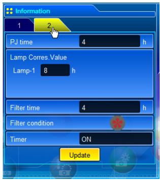
Items Description
PJ time..................................................Displays the accumulated use time of the projector.
Lamp Corres.
Value.................................................. Displays the use time (Corresponding value) of the lamp.
Filter time..................................................Displays the use time of the filter.
Filter condition. Displays the filter condition with an animation.
Timer..................................................Displays the timer setting status.
ON Timer has been set.
OFF No timer setting.
Indication of the filter status
| Icon display/background | Status |
| Blue | Good condition. Fan speed is normal. |
| Blue | Good condition. Fan speed is maximum. |
| Yellow/Gray | Filter is almost clogged. Fan speed is normal. |
| Yellow/Gray | Filter is almost clogged. Fan speed is maximum. |
| Red/Gray | Filter is clogged. Replace a filter with new one. |

Multi-control
Controlling and setting the multi-projectors
This function enables you to control the multiple projectors equipped with the network units that are connected to the network. Click Multi Control on the main menu to display the control page.
Note:
To control the multiple projectors, each projector must have the same Network PIN code.
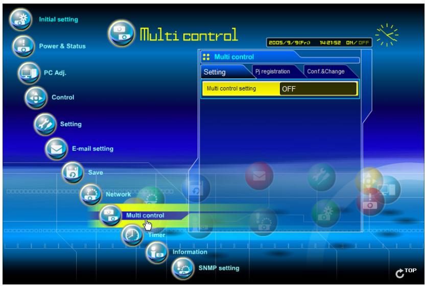
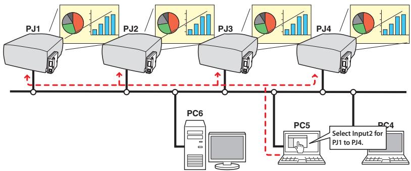
Example of multi control
Start/stop the multi control
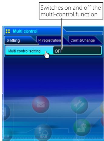
To start or stop controlling the multi-projectors, click Multi control setting menu and select ON or OFF.
Multi control setting
OFF.....Stops multi control function
ON....Starts multi control function. The multi control menu will appear when setting ON. These items of menu are linked to the main menu.
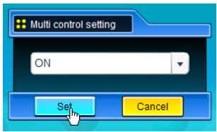
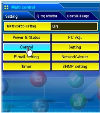
The multi controllable menus are "Power & Status", "PC adjustment", "Control", "Setting", "E-mail setting", "Timer", "SNMP setting" and "Network Viewer". Click each menu and perform setting and adjustment.
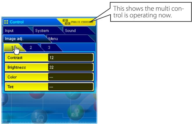
The word "MULTI CONTROL" appears on the each control page while the multi control is operating.
Register the projector
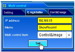
To use the multi control function, register the IP address of the projector you intend to control. Click PJ registration sub menu tab and set the IP address, Memo and Multi control item, then click Set button.
Items Description
IP address.......Enter IP address of the projector to control
Memo....................................Enter projector name or installed location etc.
Multi control item
Control.Controlling the projector
Control & Image.... Controlling and displaying images
Image.................................................. Displaying the images
Confirmation of registered projector
To check the registered information, click Conf. & Change sub menu tab. The registered information of the projector is listed as the below.
-
The word "none" is displayed if not using the "Memo" function.
-
When you click on a listed IP address, the login page for the selected projector will be displayed with a new window.
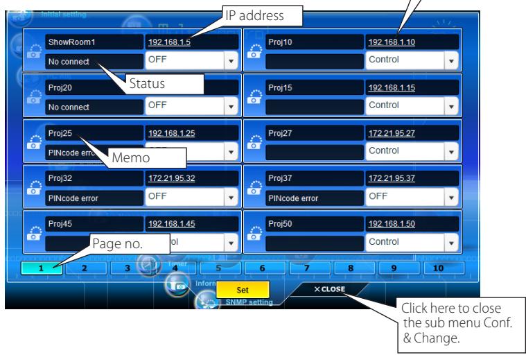
10 projectors per page can be registered and up to 100 sets can be registered for the multi-control.
Change the mode of the registered projector
To change the mode of the registered projector, select a mode with the pull-down menu button under the IP address of the target projector and then click Set button.
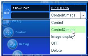
Mode Operation
Control. Controlling the projector
Control & Image..... Controlling and displaying images
Image Displaying the images
OFF. Excluding from the multi-control
Delete. . . . . . . . . . . . . . . . . . . . . . . . . . . . . . . . . . . . . . . . . . . . . . . . . . . . . . . . . . . . . . . . . . . . . .
- The multi control item is not changed during using the network viewer function. It is not available with the light mode.
Status
If some of the registered projectors are disabled by some reasons (such as disconnecting the power source, disconnecting the LAN cable, disconnecting from the network), control changes will continue to be effective for the projectors that are still active. At the same time, the deactivated projectors are excluded from the multi-control. The status of the registered projectors are indicated under the projector name. See the table below for status indications.
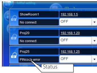
Status Description
(blank)............The projector is connected to the network correctly
No connect....The projector may not be connected to the network. Please check the connection and network configuration of this projector.
PIN code error............The PIN code is incorrect. The PIN code for the multi-controlled projectors must be the same. Change the PIN code of this projector to the common PIN code.
File Error Not displaying the images. Check if this projector is using the Network Capture function or Network Viewer function individually, or in the standby mode.
- The network unit updates the status at the time when the multi-control function was executed.
If the multi-controlled projector is in the standby mode, any change is not effective except timer setting.
Cannot register, delete or change the multi-control setting during using the network viewer function.
It is recommended that a specified projector should be chosen for setting as a master when you use this multi-control function. The control for the multi-controlled projectors will become too complicated operation if this function is used for each projector.
If the registered projector is not connected to the network, it will take some time to complete the multi-control operation because of waiting for the response from each registered projector.
There are some disabled items in the multi-control function for the light mode.
Conf. & Change page in the light mode
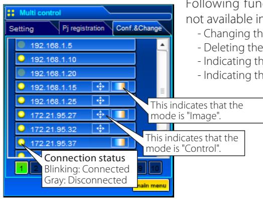
(Conf.&Change page in the light mode)
Following functions in the "Conf. & Change" page are not available in the light mode.
- Changing the control mode.
- Deleting the registered IP address
- Indicating the each status
- Indicating the each memo
Controlling all together
"Power & Status", "PC adjustment", "Control" and "Setting" can be controlled all together. Set "ON" the multi control setting and adjust controls of each menu. The setting value is applied to the registered projectors sequentially.
This is effective only if the multi control item of the registered projector sets to either "Control&Image" or "Control".
Setting all together
"E-mail setting", "SNMP setting" and "Timer" can be set all together. Set "ON" the multi control setting and items of each menu. The setting value is applied to the registered projectors sequentially.
This is effective only if the multi control item of the registered projector sets to either "Control&Image" or "Control".
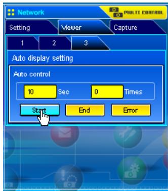
Viewer auto setting all together
"Viewer auto display" can be set all together. Set "ON" the multi control setting and select [3] Auto display setting from Viewer sub menu (selected by "Multi-control" - "Network Viewer" menu). Set the display time periods and repeat times for the auto image display. When clicking Start button, the registered projectors start playing back the auto image display in sequential.
For further information of the Auto display, see "Using the network viewer function". (p.98)
This is effective only if the multi control item of the registered projector sets to either "Control&Image" or "Image".
Chapter 5
Network Capture
Network Capture is a function to display the screen image of the computer via the network.
Real Time Capture
- Network Communication
5
About Network Capture function
The Network Capture is a function to project the screen images of the computer which has a Network Capture 3 software by the projector through the network. This function has 2 kinds of mode as the below.
Real Time Capture (p.72)
A function to display the screen image of the computer by the projector through the network in real time.
- Network Communication (v p.77)
This mode is to communicate by sharing the capture image of a computer with multiple computers and a projector. User can draw the text and figure on the captured image by using a drawing tool.
Up to 30 computers can be registered.
The Network Capture function cannot be used when using the Network Viewer function. The Real Time Capture and Network Communication mode cannot be used at the same time.
Launching the Network Capture 3
After installing the Network Capture 3 software, the shortcut icon is copied into the "Startup" folder. When you boot the computer, the Network Capture software also starts and its icon stays on the task bar. If the icon is not appeared on the task bar, the Network Capture 3 software is not starting. Click "Network Capture 3" from "Start" - "All the Programs" - "Network Viewer & Capture 3" menu to launch it manually. The status which the Network Capture 3 icon stays on the task bar is just preparing the screen capturing.

Commands on the task bar
When clicking the Network Viewer & Capture 3 icon on the task bar, The popup menu will appear as the right. See the next page for each operation.
Start real time capture
Start Commu
Parameter set up...
Version information...
Shut down
Items Description
Start real time capture....Starts the real time capturing. (p.72) The screen image of the computer is projected on the screen in real time.
Start communication ........Starts the Network Communication. (p.77) Captured image is projected on the screen. The captured image edit window appears on the computer screen.
Parameter set up.... Sets the communication parameter between the computer and network unit of the projector. For further information, see item "Parameter set up" below.
Version information..................................................Displays the version of this software.
Shut down . Quits the application.
Parameter set up
1 Click Network Capture 3 icon on the task bar.
2 Click "Parameter set up" on the popup menu. The setting window will appear.
3 Set Capture Port and PIN code to match to the projector's port number and Network PIN code.
To check the Capture Port number, see item "Control by the web browser" (p.74). To check the PIN code, see item "Network PIN code setting" (p.22).
Specify the port number of TCP/IP. The default port setting is 9000. There are some reserved port numbers and also some applications may use their own port numbers. If one of those port numbers is used, the alert dialog window will appear and let you know that it is an invalid port number. In this case, use another port number.
The reserved port numbers are http (80), ftp (21), telnet (23), etc. The port no. 4352, 10000, 10001 are reserved to control the projector through the LAN port.
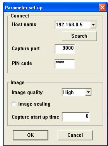
4 Click Search button to list up the available IP address
assigned to the projector and select desired IP address you use, or you can enter the IP address or host name manually if you know that IP address or host name.
It may not find any address over the router. Consult your network administrator for further details.
5 Set the quality of the image.
Quality: Selects from High, Mid, Low
Image Scaling: If checked, the screen image size of the computer is automatically adjusted to the projector's screen size.
6 Set capture start time in second unit.
This is effective in the communication mode only. It sets up the time period from executing the command "Capture transfer" to capturing and transferring the actual screen image. 0 to 60 seconds can be set.
7 Click OK button to close the setting window.
About Image Quality
Quality : Quality mode of the captured image shows following JPEG compression mode;
High : JPEG low compression mode
Medium : JPEG medium compression mode
Low : JPEG high compression mode
Using the Real Time Capture
This is a function to project the screen image of the computer by the projector in real time. The captured image projected by the projector can be selected from the computer, web browser and the projector respectively.
Registering the computers
Up to 30 computers can be registered.
1 Access to the control page of the projector by using the web browser. From the Network menu, click Capture tab to display the setting page (p.37).
2 Switch to Connection setting page by clicking the page number tab [3]. Enter the IP address of the computer to the PC number, and then click Set button. Click Set button to register the IP address for each page.
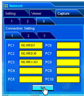
The registered computer enables to start capturing if only the Network Capture icon appears on the task bar.
The transfer speed of the captured image using the Real Time Capture function is depending on the network environment and data volume of the image. For example, when transferring an image (Computer resolutions and colors: XGA, full color, Picture quality: High), the transfer speed is about 2 pages per second in maximum. It cannot be supported for movie pictures.
The mouse pointer on the computer's screen cannot be captured.
[1] Control by the computer
![SANYO PLC-XT35 - [1] Control by the computer - 1](/content/2025/01/96763/images/5750f3e4e6aa6365d5ca700de27d235afb79c7e9ae55bb83fa17ffdac5589a11.jpg)
Select input mode to "Network" previously.
1 Click Network Capture 3 icon on the task bar.
2 Click Start real time capture on the popup menu. The screen image of the computer will appear on the projected screen in real time.
- To stop capturing, click Stop real time capture on the popup menu. The captured image of the computer on the screen is frozen.
- To restart capturing, click Restart real time capture on the popup menu.
3 To end capturing, click End real time capture on the popup menu.
![SANYO PLC-XT35 - [1] Control by the computer - 2](/content/2025/01/96763/images/276affa612d565c22b676f22962adf739e325bdc15ea6b4593a31c66303f1f76.jpg)
![SANYO PLC-XT35 - [1] Control by the computer - 3](/content/2025/01/96763/images/eb7e4b5889b54f81e8e3278b7c4e2bb7d236caf15e56296d891212a0d00fd7af.jpg)
If the Network PIN code set on the projector differs from PIN code set on the parameter setting up, The Pin code setting window appears. Enter a correct PIN code and click OK button.
![SANYO PLC-XT35 - [1] Control by the computer - 4](/content/2025/01/96763/images/25d5e8f1a2b13bcf94af2b98f4719c74b33fd1039676c1f9999b01bca57b4b87.jpg)
If the error message appears, check item "Parameter set up" (p.71).
[2] Control by the web browser
![SANYO PLC-XT35 - [2] Control by the web browser - 1](/content/2025/01/96763/images/ce43806828f2b6c5e60ffe143305f70709b5a09c8ed8544a4a8157be30b658e8.jpg)
Select input mode to "Network" previously.
1 Access to the control page of the projector by using the web browser. From the Network menu, click Capture tab to display the setting page (p.37).
2 Select the computer number from the pull-down menu button of "Connecting PC" and click Start button. The screen image of the selected computer will appear on the projected screen in real time.
- To stop capturing, click Stop button. The captured image of the computer on the screen is frozen.
- To restart capturing, click Restart button.
3 To end capturing, click End button.
![SANYO PLC-XT35 - [2] Control by the web browser - 2](/content/2025/01/96763/images/0c9c04ae3ee76dca4cdb2a25517b2c696475a4154d92cde64ebcdd605ae23733.jpg)
The IP address of the connecting PC should be registered previously (p.72).
If the error message appears, check item "Parameter set up" (p.71).
You can use the capture function by using the web browser or the projector if the Network Capture 3 software is installed into the computer correctly and its icon stays on the task bar.
[3] Control by the projector
![SANYO PLC-XT35 - [3] Control by the projector - 1](/content/2025/01/96763/images/df4a8496fe17d8526071b450f8c7a2fbb185994e9c7d8d45f9915511c3554dd1.jpg)
Select input mode to "Network" previously.
1 Select "Network Capture" icon from "Network" menu. Press SELECT button on the projector twice to display the network capture setting pallet.
2 Select PC number to connect.
3 Select "Connect" and then press SELECT button to start capturing. The screen image of the selected computer will appear on the projected screen in real time.
4 To end capturing, select "Disconnect" and then press SELECT button.
![SANYO PLC-XT35 - [3] Control by the projector - 2](/content/2025/01/96763/images/68df21394f28f506af5d44137f48cf2cfee429fcaefe2fc088deec647bdb87f8.jpg)
The IP address of the connecting PC should be registered previously (p.72).
If the error message appears, check item "Parameter set up" (p.71).
Selectable computer from the projector is PC1 to PC10. Other PCs cannot be selected from the projector.
The projector does not provide the function to register the IP address of the computer and to set the parameter of the capturing. They should be registered by using the web browser previously (p.71-72).
Advanced using example
Displays the presentation data stored in the computer by using the wireless mouse function from the projector.
1 Start capturing of the computer PC1 by using the projector.
Select "Network Capture" icon from the menu and select "PC1" and then select "Connect" (p.75).
The Network Capture software installed in the selected computer will start capturing.
2 On the PC1 capture image projected on the screen, search a presentation file data stored in the PC1 by using the wireless mouse function of the remote control supplied with the projector.
3 Select a desired file and double click with the remote control.
The application by which the document was created starts and the projector projects the presentation picture on the screen.
4 Start the presentation.
By using wireless mouse function, control the page browsing and some other operations for the PC1.
For further instructions of the wireless mouse, please refer to the projector's owners manual.
On the projected screen using with the network capture, the shape of the mouse pointer differs from the one on the computer's screen.
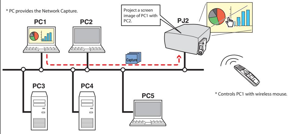
* PC provides the Network Capture.
Setting condition
Projector
Input mode: Network
Network Unit
Registering the connection: The IP address of the computer and proper parameter must be set to the PC1 (p.71-72).
Mouse Display: "On" (p.74, p.75)
Computer PC1
Software: The Network Capture software is installed correctly and its icon appears on the task bar.
Using the Network Communication
This Network Communication is to communicate by sharing the captured image of a computer with multiple computers and a projector. User can draw the text and figure on the captured image by using a drawing tool.
The data that has the captured image of a Main PC and communication information is sent to the projector. The projector projects this data onto the screen and serves this data to other computers (Sub PC) at the same time. The Sub PC receives served capture data and displays it on the screen. The Main PC and Sub PC also can edit the captured image by using the drawing tool. This edited image is applied to all the computers automatically.
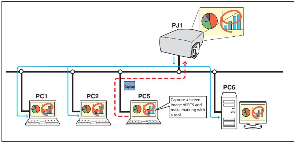
- The Main PC is a computer which started using of communication function, and serves own computer screen captured image to the Sub PC. The Main PC has an authority to quit using whole of communication. To become the Main PC, execute the command "Start Communication" or "Capture transfer". For further information, see item "How to use the Network Communication". (E§ p.81)
- The Sub PC is a computer which receives a captured image from the Main PC. On the communication mode, the Sub PC can become the Main PC anytime.
Settings before using the Network Communication
To use the Network Communication, the capture setting of the network should be set either [1] or [2] described below.
[1] Setting the network unit searches all the available target computers in the network automatically.
or
[2] Setting the target computers are registered to the network unit.
Perform capture setting following to the description below.
[1] When serving the capture data to all the target computers in the network.
By using the web browser, display "Communication setting" from menu "Network"-"Capture"-"Page 2". Confirm that the item Auto search target PC is "ON". If "OFF", change mode to "ON".
- Network unit can find up to 30 computers in the network.
![SANYO PLC-XT35 - [1] When serving the capture data to all the target computers in the network. - 1](/content/2025/01/96763/images/48bf72a2f457869c6959653bb33aa3bee9e4c06088efa4fb0c97af45040e0d25.jpg)
[2] When serving the capture data to the specific target computers in the network.
Set item Auto search target PC is "OFF" described in the above and then display "Connection setting" from menu "Network"-"Capture"-"Page 3" with the web browser. Enter the IP address of target computer and click Set button to register.
- Up to 30 computers can be registered to the network unit.
![SANYO PLC-XT35 - [2] When serving the capture data to the specific target computers in the network. - 1](/content/2025/01/96763/images/025921c10f7484a139a79418d76db84e0d24311b133bc81632c835690bab9632.jpg)
Description of capture editing window
Select menu "Start Communication" from the popup menu appearing by clicking the Network Capture 3 icon on the task bar. The capture editing window will appear on the computer screen as the below. For basic operation of each menu, refer to the item "Menu tree" below.
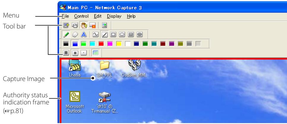
Menu tree
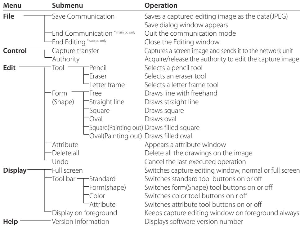
Tool bar button names
The following commands are assigned to the tool bar buttons. For each operation, refer to the description of item "Menu tree".
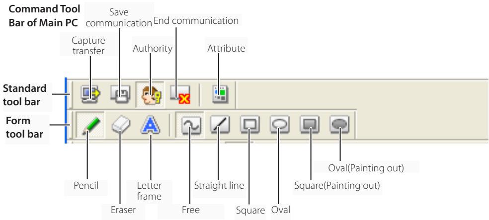
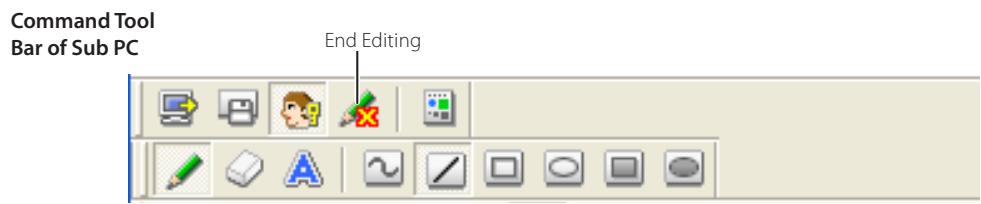
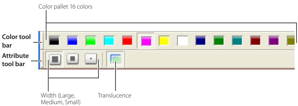
To switch the tool bars displaying on or off, select each command from menu "Display"- "Tool bar".
User can realign and join the tool bars (Standard, Shape, Color, Attribute), and change it to the floating pallet by taking a drag and drop of the tool bars.
There are some disable buttons depending on the tools and authority mode. In this case the button indicates with gray.
How to use the Network Communication
Start the communication
1 Display an image on the computer screen.
2 Select Start Communication from the popup menu appeared by clicking Network Capture 3 icon on the task bar.
The capture editing window with a captured image appears on the computer screen.
If an error message appears, check item "Parameter set up". (p.71)
The icon on the task bar is activated during the network communication operates.
Start real time capture
Start Communication
Parameter set up...
Version information...
Shut down
Icon on the task bar


Standby Communication
Join the communication (only for Sub PC)
1 Network Capture 3 icon is activated to inform users in the network that the Network Communication is operating. Display the popup menu by clicking its icon.
2 Select Start editing menu. The capture editing window with a captured image appears on the computer screen.
Start editing
End Communication
Version information...
Shut down
Exit from the communication (only for Sub PC)
Click "End editing" button on the standard tool bar. The capture editing window will be closed.
This command is available with the Sub PC only.
When executing "End editing" with the authority provided, the authority will be released.
End the communication
Click "End communication" button on the standard tool bar.
The capture editing window will be closed.
This command is available with the Main PC only.
It cannot be ended the communication while other PC has the authority. To end communication forcibly, click the Capture 3 icon on the task bar and select "Shut down" on the popup menu.
Acquire and release of editing authority
To edit the capture image, each computer needs to acquire the authority respectively. To acquire the authority, click " Authority" button on the standard tool bar and then edit the capture image. The capture editing window indicates the authority status by changing the frame color according to the current authority mode as follows.
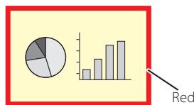
having an authority
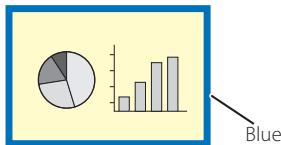
other computer having an authority
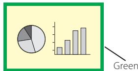
ready to acquire an authority
Edit capture image
Drawing figures
1 Click " :Pencil" button on the form tool bar.
2 Select its attribute (shape, width, color and translucence) from the form and attribute tool bar.
3 Drag a mouse pointer on the screen image to draw the figure.
Erase drawn object
1 Click "Eraser" button on the form tool bar.
2 Select its attribute (shape, width) from the form and attribute tool bar.
3 Drag a mouse pointer on the screen image to erase the figure.
Hints of the drawing
Straight line tool.......To draw the vertical line or horizontal line, drag a mouse pointer with shift key pressed.
Square tool............To draw the quadrate rectangle, drag a mouse pointer with shift key pressed.
Oval tool.... To draw the perfect circle, drag a mouse pointer with shift key pressed.
To cancel the drawing, select command "Edit"-"Undo" from the menu.
To erase all the drawing at once, select command "Edit"-"Delete all" from the menu.
The popup menu appeared by right clicking of the mouse is also available to select the tool and change the attribute.
Setting of the drawing tool attribute
When clicking " :Attribute" button on the standard tool bar, the following window will appear. This window appears only if the pencil or eraser tool is selected.
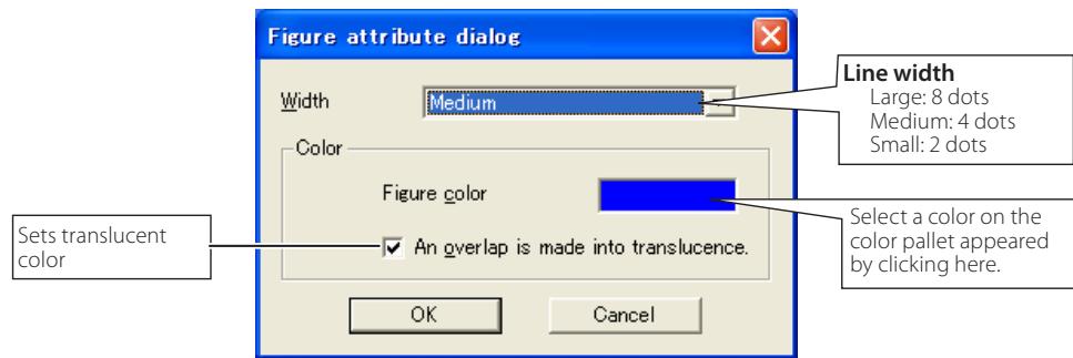
Drawing letter
1 Click "A:Letter frame" button on the form tool bar.
2 Select a color of text with color tool bar.
3 Drag a mouse pointer on the screen image to specify the area of the letter frame. The letter input dialog window will appear.
4 Enter the letter onto the window. To change the letter attribute, click Letter attribute button. See item "letter attribute setting" below.
5 Click OK button to fix the content. The entered letter appears on the captured image.
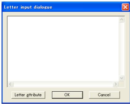
If the entered letter overflows the area of letter frame, the letter frame is automatically extended downward.
Up to 1000 characters can be used for a letter frame.
Letter attribute setting
The font attribute setting window appears when clicking " :Attribute" button on the standard tool bar with the letter frame tool selected, or clicking Letter attribute button on the letter input dialog window described the above.
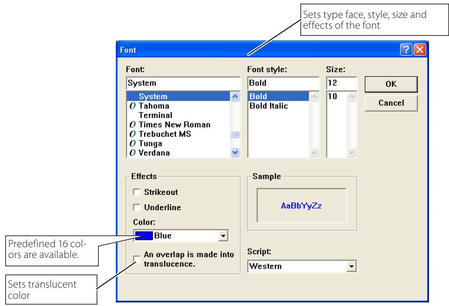
Network Communication operation and change of state
Network Communication can be used under the environment which one or more computers are connected to the projector via the network.
Preparation
Launch the Network Capture 3 software on the target computer (p.70). Set the projector in the standby or turning on. Check IP address of the target computer is registered in the connection list (p.78).
| Operation on the Main PC | Operation on the Sub PC | |||
| On the Communication | 1 Executing the command "Start Communication".→The capture editing window appears on the screen. The icon on the task bar is activated. | Frame | →The icon on the task bar is activated to let users know that the captured image is now serving. | Frame |
| R | 执行的命令 "Start Editing".→The capture image on the Main PC appears on the screen. | B | ||
| 2 Editing the capture image using with the tools.→The editing information is automatically transferred to the Sub PC. | R | →The editing information on the Main PC is reflected on the Sub PC. | B | |
| 3 Releasing the editing authority.→The color of authority status frame changes green. | G | →The color of authority status frame changes green. | G | |
| →The color of authority status frame changes blue. | B | Acquiring the authority.→The color of authority status frame changes red. | R | |
| →The editing information on the Sub PC is reflected on the Main PC. | B | Editing the captured image using with the tools.→The editing information is automatically transferred to the target PC. | R | |
| →The color of authority status frame changes green. | G | Releasing the editing authority.→The color of authority status frame changes green. | G | |
| 4 Acquiring the authority.→The color of authority status frame changes red. | R | The color of authority status frame changes blue. | B | |
| 5 Repeat steps 2, 3 if required. | Repeat steps 2 to 4 if required. | |||
| 6 Executing the command "Capture transfer".→Updating the editing window with a new captured screen image. | R | →A new captured screen image appears on the editing window. | B | |
| 7 Repeat steps 2 to 5. | ||||
| 8 Ending the communication.→The capture editing window disappears. | R | The capture editing window disappears. | ||
The projector projects the edited captured image on the screen when the input mode of the projector is set "Network".
The command "Save Communication" can be executed in any of the mode even if not having the authority.
The arrow () shows a response to the command executed.
The execution of the command "End Communication" or "End Editing" on the Sub PC has no effect on the other target computers.
Executing the forcing mode
The network capture setting of the web page provides a forcing executing command. This command executes the release of authority or ending the communication forcibly. This is useful when the other target PC keeps an authority all the time, or when the condition of the communication is not stable.
Click page 2 Communication setting from the menu "Network"-"Capture". Execute command by clicking the button Free, Quit or Update.
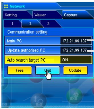
. Displays IP address of the Main PC
Displays IP address of the computer has a editing authority
Item Description
Free. Releases the editing authority forcibly
Sets condition which all the users can acquire an authority
Quit... Quits the communication forcibly
The capture editing window on all the computers closes forcibly.
UpdateAcquires the latest communication status
Updates the IP address of the Main PC and Update authorized PC.
Error information
| Error messages | Cause and corresponding |
| Set up the parameter. | Error when executing the communication. The parameter setting (host name, capture port) has not been set. → Check parameter setting (p.71) |
| It has not been registered to PJ as a group. | Error when executing Start Communication or Start real time cap-ture. The IP address of the computer has not been registered. → Register the IP address by using the web browser (p.78) |
| Cannot be displayed as PJ is under display. | Error when executing Start Communication or Start real time cap-ture. The other capture, viewer or advanced card imager function is now operating. → Wait until the communication function is available. |
| Cannot connect to PJ. | Cannot establish the connection with the network unit when executing the Start communication, End communication, Capture transfer, Start real time capture or End real time capture. → Check connection of the network cable. |
| Cannot transfer data to PJ. | Cannot transfer the data to the network unit when executing the Start Communication, End Communication, Capture transfer, Start real time capture or End real time capture. The time out period is 10 seconds. → Check connection of the network cable. |
| Cannot receive data from PJ. | Cannot receive the data from the network unit when executing the Start Communication, End Communication, Capture transfer, Start real time capture or End real time capture. The time out period is 10 seconds. → Check connection of the network cable. |
| Other PC has authority. Cannot complete "Network Communication". | When executing the End communication, you cannot quit the communication because other computer has an authority |
| Other PC has authority. Cannot obtain authority. | Other computer has an authority. |
| The server name or address could not be resolved. | When setting the parameter, the computer cannot find the setting host name or IP address in the network. → Use available host name or IP address. |
| Invalid port number | When setting the parameter, the reserved port number is speci-fied. → Check parameter setting (p.71) |
| PJ has not started Network Communication. Close the window and open it again. | The projector might have turned off during the communication. → Check projector power and restart executing "Start communica-tion". |
Chapter 6
Network Viewer
Network Viewer is a function to display the image data stored in the file servers by the projector through the network.
Describes about file converter software File Converter 1, File Converter 2 and program creator software Program Editor, and how to use Network Viewer.
6
Creating the available data [Network Viewer 3]
The image available with this projector is the JPEG format (.jpg). There are several types of JPEG data. Before using the images with the Network Viewer function, it should be converted to the optimized JPEG data for this projector.
[1] How to use the Network Viewer 3 (File Converter 1)
The File Converter 1 is a software to convert from the JPEG, bitmap or Power Point data to the optimized JPEG data for the projector.
Launch and quit the File Converter 1
To launch the File Converter 1, click "Network Viewer 3 (File Converter 1)" menu from "Start" - "All Programs" - "Network Viewer & Capture 3" menu.
To quit the File Converter 1, click on the close box on the upper right hand of the window.
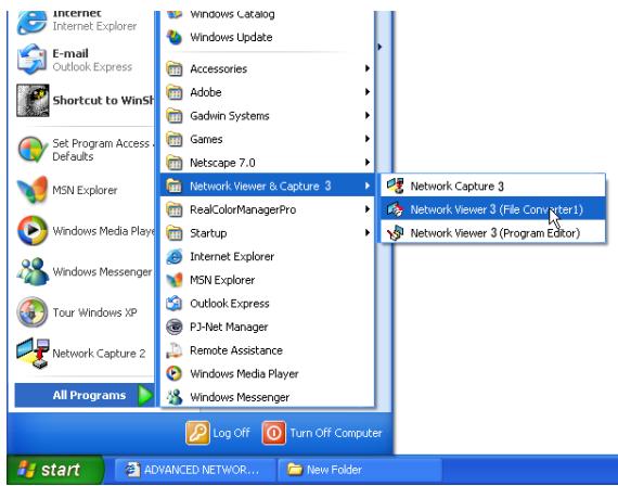
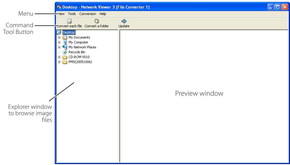
File Converter 1 window
Menu Tree
| Menu | Sub Menu | Description |
| View | Update | Updates contents of the preview window |
| Preview size | Sets size of the preview image, Large, Middle, Small | |
| Tools | Option | Sets default of the output destination and conversion mode |
| Conversion | Convert a folder | Converts files in a folder into JPEG files at once. |
| Convert each file | Converts a file into a JPEG file individually | |
| Help | Version information | Displays the version information |
Command Tool Button
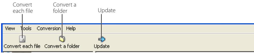
Create the available data
1 Select a folder in which the image files are stored by the explorer window.
The preview images of the available image data (JPEG file, Bitmap file, power point file) in the selected folder are displayed on the preview window.
On the preview window, the preview displayed with the red frame represents a file not optimized JPEG file or Bitmap file for the projection. The preview without the red frame represents the optimized JPEG file for the projection. So you do not need to convert them again, but if you change the size or image quality, perform to convert them again.
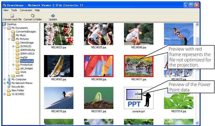
2 When converting each file, select a preview image first and then click Convert each file.
To select two or more files at once, press and hold "Shift" key or "Ctrl" key and then click the preview images.
When converting all the files in a folder, select a folder and click Convert a folder.
3 As the confirmation window appears, check the conversion object and conversion type and then click OK button. The File converter 1 starts converting and stores the optimized files into the output folder. It enables you to select a local hard disk of your computer, shared computer in the network, a directory of the FTP server. To change the conversion type or output destination, click Change button.
If the power point file is included in the conversion object, the Microsoft Power Point software will be launched and start converting automatically.
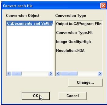
Dialog window when using "Convert each file" and "Convert a folder"
Setting of output destination and conversion mode
When clicking Change button on the confirmation window in the step 3 on the previous page, following option setting window appears.
Output destination
Select either Folder or FTP server as the output destination of the converted files.
Folder
Output folder....Specify a folder in the local hard disk or shared computer in the network
FTP server
Host name....Enter host name or IP address of the FTP server
Root Folder......Specify the root directory of the FTP server. Normally use "/".
User ID.......Enter your login account of the FTP sever.
Password............Enter your password of the FTP server.
Output folder....Specify a directory of the FTP server.
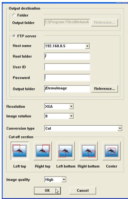
Conversion mode
Resolution......Selects output image resolution (VGA to SXGA+)
The image resolution higher than the projector's panel resolution cannot be displayed.
Image rotation....Selects image rotation (0, 90, 180, 270).
Conversion Type
Fit....Converts as either width or height of the image sets to be the maximum screen width or height.
Justify
[both ends]....Converts as width of the image sets to be the maximum screen width.
Justify
[top and bottom]....Converts as height of the image sets to be the maximum screen height.
Cut.... Cuts image with the screen size not depending on the image size. This type has several modes, see the figure right.
Select this mode when you want to have the images with the original size. Select each mode by clicking on the button.
Image Quality....Selects an image conversion quality with "High", "Mid" or "Low".
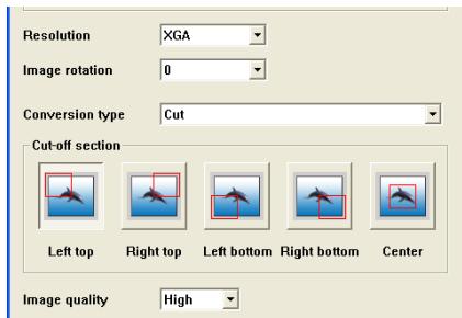
[2] How to use the Network Viewer 3 (File Converter 2)
The File Converter 2 is a kind of the printer driver software to convert to the optimized JPEG data for the projection from the any documents created by the other software such as text editor, spreadsheet or presentation software. It is possible to convert to the JPEG file from the any kinds of documents created by the software which has a "print" menu.
Create the available data
1 Open a document with the individual software.
2 Select a "Print" sub menu and open the printing dialog. On the window, select "Network Viewer 3 (File Converter 2)" icon on "Select Printer" item and click Print button.
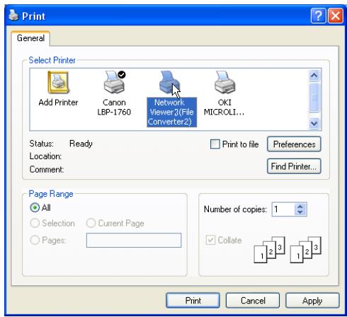
Set the option setting for the page layout or paper setting by clicking Preferences button if required.
3 Select a folder and click Save button.
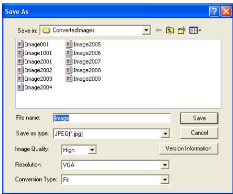
The file name is named with "Image001" as the default. If the converted image has 2 or more pages, the file names are numbered from "001" to "999" in a sequential order.
Image quality and Conversion type can be setup on this window. For further information, please see "Setting of the Conversion Mode" (p.91).
It may appear the white space around the edges on the converted image depending on the type of the image data.
Creating a program file [Program Editor]
Network Viewer 3 (Program Editor) is a tool to make a program file which specifies the display order of the image and its file path in the file server (FTP server). The Program Editor makes a folder "DispParam" at the login root directory in the FTP server and makes files as each program name into this folder. These files are called "Program". By specifying the program file with the Network Viewer function, you can have the programmed display with the projector.
Procedure of making program
1 To launch the Program Editor, click "Network Viewer 3 (Program Editor)" menu from "Start" - "All Programs" - "Network Viewer & Capture 3" menu.
2 Click Connect button.
3 If the connection setting window appears, enter the each item and then click OK button.
The setting window disappears and then the programs are listed on the window if there are program files at the login directory in the connected FTP server.
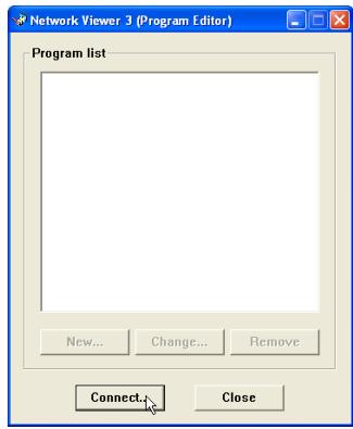
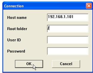
Item Description
Host name.......Enter the FTP server name or IP address
Root Folder ....................Specify the root directory of the FTP server. Normally use "/".
User ID......................................Enter your login account of the FTP sever or use blank when you login as anonymous account for the FTP server
Password............Enter your password (PIN code) or use blank when you login as anonymous account.
IMPORTANT
It is required to set the write permission mode for the login directory of the FTP server. If only the read only mode, you will have an error when you register a new program.
4 Click New button.
5 Enter a program name and click Add button.
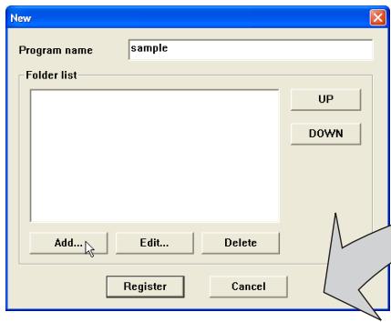
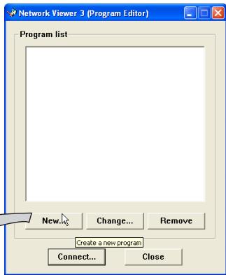
Change : Changes the contents of the program file.
Remove : Removes the program from the list.
6 The folder selection window appears and select a folder in which the JPEG data are stored and then click Add button to register into the folder lists.
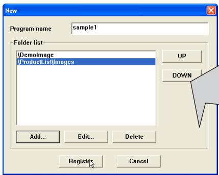
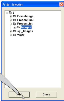
Add.................................................. Displays the folder selection window.
Delete.......Deletes the folder path from the folder list.
UP.......Moves up the selected folder path.
DOWN ......Moves down the selected folder path.
Edit.... Used to set up the display order or display time of the image individually. For further information see item "Setting up the display order and time of the images" on the next page.
The order of the display is listed in the folder list window. To change the order of the display, change the list order of the folder list by using UP or DOWN button.
The programs are stored into the "DispParam" folder at the login root directory and this "DispParam" folder is made by software automatically.
7 Click Register button to register the folder list into the program.
8 Click Close button to quit the Program Editor.
Setting up the display order and time of the images
In the default setting, the display order of the images is ASCII code order of the file name. To change the display order or to set up the display time, take the following procedure.
Display the folder list window in step 6 of the previous page.
1 Select a folder list contains images to change.
2 Click Edit button. The images in the selected folder are displayed with the file name on the index window.
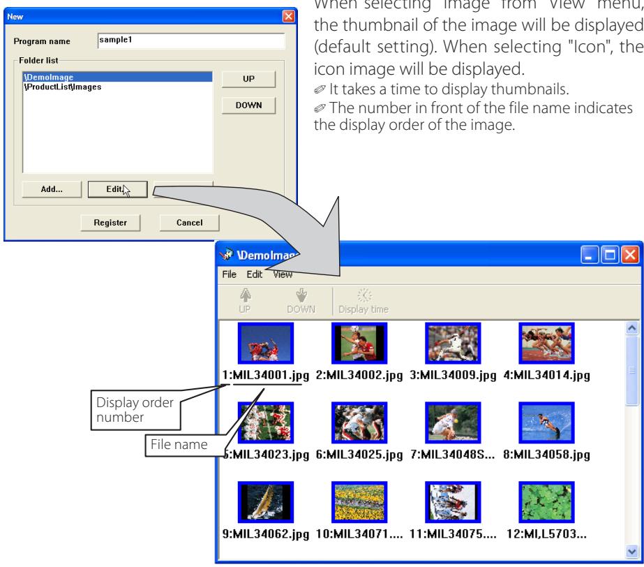
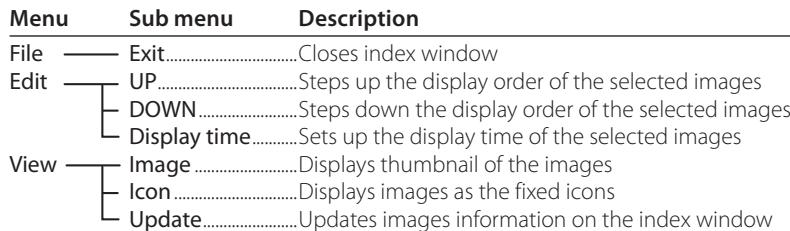
3 To change the display order, select*1 files and then click UP or DOWN button on the menu bar to move them onto your desired place, or select files and then drag and drop them onto your desired place with mouse.
4 To change the display time*, select*1 files and then click Display time button on the menu bar to display the Display time setting window. Check "Display time" check box and set display time. To cancel the display time, un-check the "Display time" check box.
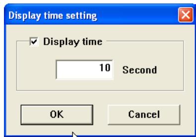
Image frame on the index window
Image frame on the index window has 3 kinds of display modes as follows.
No frame
: Shows that the image in the folder is unchanged
Blue frame
: Shows that image is added into the folder newly
Red frame
: Shows that image is deleted from the folder
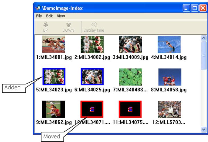
1 Enable to select multiple files at once by using "Shift" or "Control" key, or with mouse cursor.
2 Enable to set up 3 to 240 seconds for display time.
Example of the created program selection
Use the web browser to access to the control page of the projector. Click Viewer of the Network menu on the web page, then connect to the FTP server and select the program name which was made at previous section. The projector starts displaying the images along the program. For further information, please see "Using the Network Viewer function" (p.98).
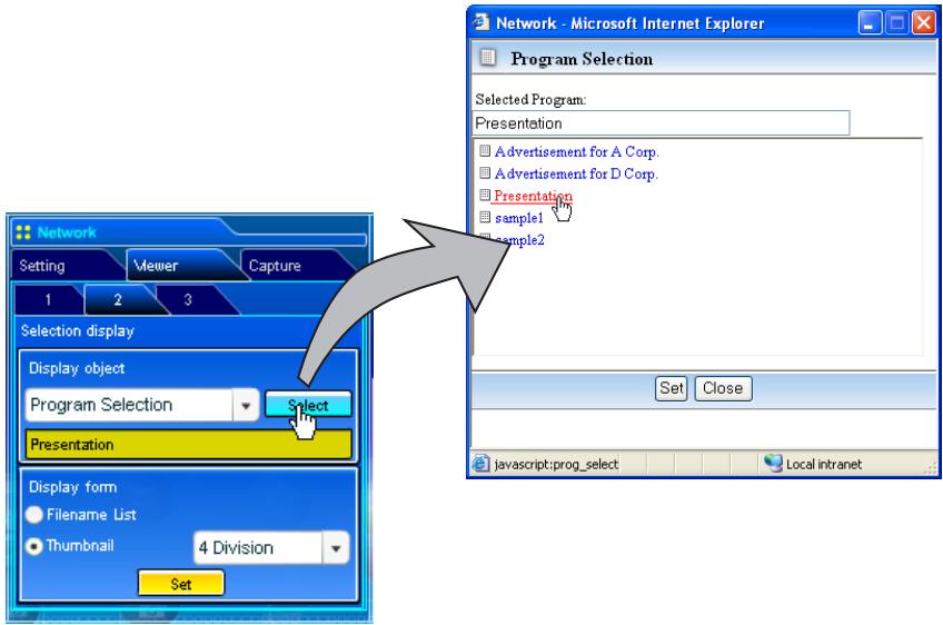
This function is not available in the light mode.
The limitation of the Program file
There are several limitations for the program file as follows;
- Number of programs in a root folder is less than 1000.
- Number of folders in a program is less than 100.
- Total characters of folder name is less than 255.
- Total characters of program file name is less than 63.
- Do not make a program name started with ".
- Do not make a program name contained with following characters:
$$ \backslash /:, ; ^ {*} ? ^ {\prime \prime} < > | $$
- The program name started with " " (space) is registered with removing the space.
Using the Network Viewer function
The Network Viewer is a function to acquire the JPEG image data from the file servers placed in the network and project them on the screen. The projected image data are specified with the folder unit. You can set the display period and repeating times, and also you can register those folders as the program. *The network viewer function cannot be used when using the network capture function.
Condition to use the Network Viewer function:
- Enables to use the FTP service with Windows 2000 Professional or XP Professional.
- User must have a full-access account to the FTP server or the FTP server allows anyone to use with "Anonymous" account which also has a full-access mode.
- The allowed number of simultaneous access from the same IP address is more than 20.
To use this function, it is necessary to disable "pop-up block" function of the web browser.
[1] Control by the web browser
![SANYO PLC-XT35 - [1] Control by the web browser - 1](/content/2025/01/96763/images/877fcc1fcb5ee8ae8a71cba333a17fb8720fc74c378580b3d163d9b2ec8e1916.jpg)
Select input mode to "Network" previously.
1 Access to the control page on the projector by using the web browser.
From the main menu, click Network - Viewer to display the setting page.
2 Setup the setting page [1] of Image display setting.
Item
Description
Host name......................................Enter the host name or IP address of FTP server, yourftp.server etc.
Folder Path....Use "/"/(root directory) in normal, or enter the directory name follow the "/"/ as shown in the below example if you have a specified direc tory in the server. /data/
User ID*1.......Enter your login account of the FTP server
Password*1......................................Enter your password of the FTP server
Option*1....Set "Display ON" when you display the acquired preview images on the web browser.
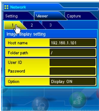
3 Setup the setting page [2] of Selection display setting.
Click Select after selecting from the pull-down menu "Folder Selection" or "Program Selection" for the Display object. The list window appears and select a program or folder and then click Set on the window.
![SANYO PLC-XT35 - Setup the setting page [2] of Selection display setting. - 1](/content/2025/01/96763/images/11115fc40eb46800361b80fc03a37488372c84980bcb1f1293702ba408682c32.jpg)
Selects the display type either the listed with file name or listed with thumbail. The thumbnail can be selected "4 division", "6 division" or "9 division".
This function is not available in the light mode.
See item "Creating a Program file [Program Editor]"(p.93) for about program.
*1 IMPORTANT NOTICE
Please note that if you use the FTP server with personal account except anonymous account, the user ID and password may be displayed on the browser depending on the version of the browser. We recommend that this function should be used with the anonymous account usually.
When clicking Set, the file list or preview list of the selected folder or program is displayed on the window.
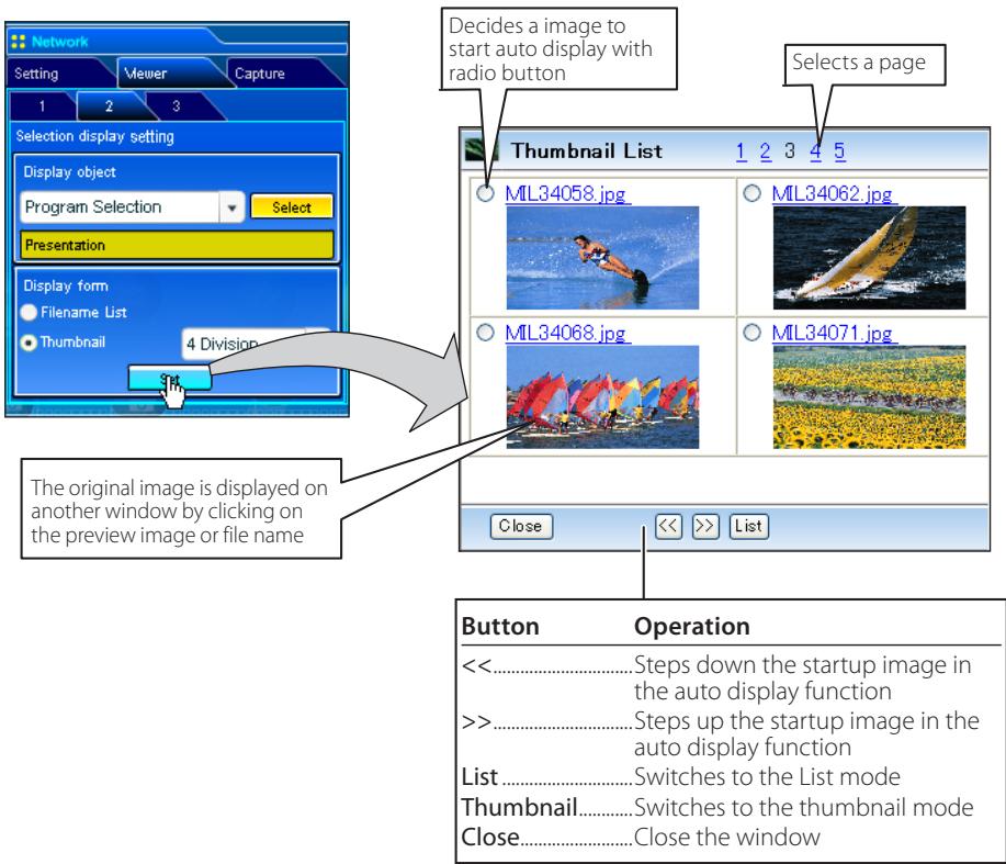
This function is not available in the light mode.
The preview image will not appear when the option is set "Display OFF".(p.99)
Up to 1000 images can be displayed.
When selecting "folder selection", it displays images placed at the first directory in the selected folder.
The display order of the images is according to the ASCII character order when selecting "folder selection", or is specified by the Program Editor when selecting "program selection".
4 Auto Display setting and control page [3]
![SANYO PLC-XT35 - Auto Display setting and control page [3] - 1](/content/2025/01/96763/images/20c9efa464c6e9b039b20287a0693096fd79df4717ce0f09712e30230a6cf756.jpg)
- Click Start button to start the auto-display. The image in the selected folder or program is displayed on the projector's screen. The web browser opens another window and displays the preview images on the Auto Control window sequentially.
-
Click Stop button to stop the auto-display.
-
Restart the auto-display, click Restart button.
-
During the auto-display stops, it enables you to display the images manually by using [<<] or [>>] button.
-
Click End button to end the auto-display.
-
When pressing the Error button, the further information of the file error is displayed.
For further error information, refer to the next page.
*1 When selecting the program file for auto-display, the display time of each image gives preference to the setting specified by the program file over the setting specified by the auto-display function above. The images not set the display time is according to the display time specified by the auto-display function above.
The display period is greatly affected by the network environment or the operation of multi control, so it may not display the image as the specified display period.
The switching is not the same timing between the images on the screen and on the web browser.
Error information
| Error type | Description |
| File Error | It is displayed when the network unit cannot acquire the correct file images from the FTP server, or when the master projector is turned off during the multi-control. Click Error button to check the details. |
| Connection Error | It may be displayed when the slave projector is using the Network Viewer or Capture function during the multi-control. Check which projector has an error, see item "Multi Control/Conf. & Change" (ESP p.64-65). |
When the file error is occurred during the auto-display, you may have the alert e-mail message. For further information, please see item "3 Option selection for sending alert mail" (p.39).
[2] Control by the projector
![SANYO PLC-XT35 - [2] Control by the projector - 1](/content/2025/01/96763/images/7ba4d975c4ee227c7d9e02720fbaaf04e81236befff3f74a1a4a6c7381cacdcd.jpg)
Select input mode to "Network" previously.
1 Select "Network Viewer" icon from "Network" menu. Press SELECT button on the projector twice to display the network viewer setting pallet.
![SANYO PLC-XT35 - [2] Control by the projector - 2](/content/2025/01/96763/images/058a60dff744da79db483d647bfd2c018003a12c01292b5e635aea8a6722133b.jpg)
2 Select "Auto" or "Manual" and then press SELECT button. When selecting "Auto", Set display time and repeat times
3 Select "Connect" and then press SELECT button to start displaying. The images in the FTP server are displayed on the screen.
It enables you to browse the images by using the control buttons ( ,) on the remote control or on the projector.
4 To end displaying, select "Disconnect" and then press SELECT button.
Item Description
Auto............ Auto display mode. Specifies display periods and repeating times
Sec. ......Display period of the image (3 to 240 sec.)
心 .Set "On" if the endless playback mode
Times...repeat times (255 times maximum)
Manual......... Manual display mode. Controls image display (browsing image backward or forward) manually.
In the automatic displaying mode [Auto], when the left-click on the remote control is pressed, projector stops automatic displaying and sets into the manual displaying mode. When pressing the right-click, it starts automatic displaying again.
The image data used for this function are the program or folder that the Network Viewer function used last time. The projector cannot specify particular images or file servers itself.
The display period is greatly affected by the network environment or the operation of multi control, so it may not display the image as the specified display period.
Chapter 7 Appendix
Connection examples
Web browser setting
Technical data
Q&A
7
Examples of connection
Peer-To-Peer connection
Connecting the projector (PJ01) to the control computer (PC05) directly.
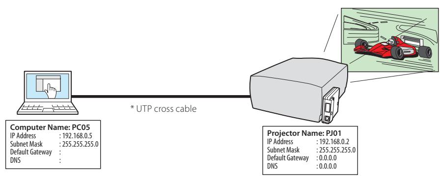
Connecting the projector (PJ01) to the control computer (PC05) via the hub.
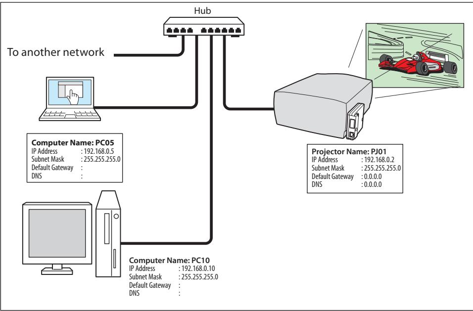
When the projector is connected to the computer directly without hub, the UTP cross cable should be used.
The gateway (Router) installed in the network
Connecting the projector (PJ01) to the control computer (PC05) via the gateway.
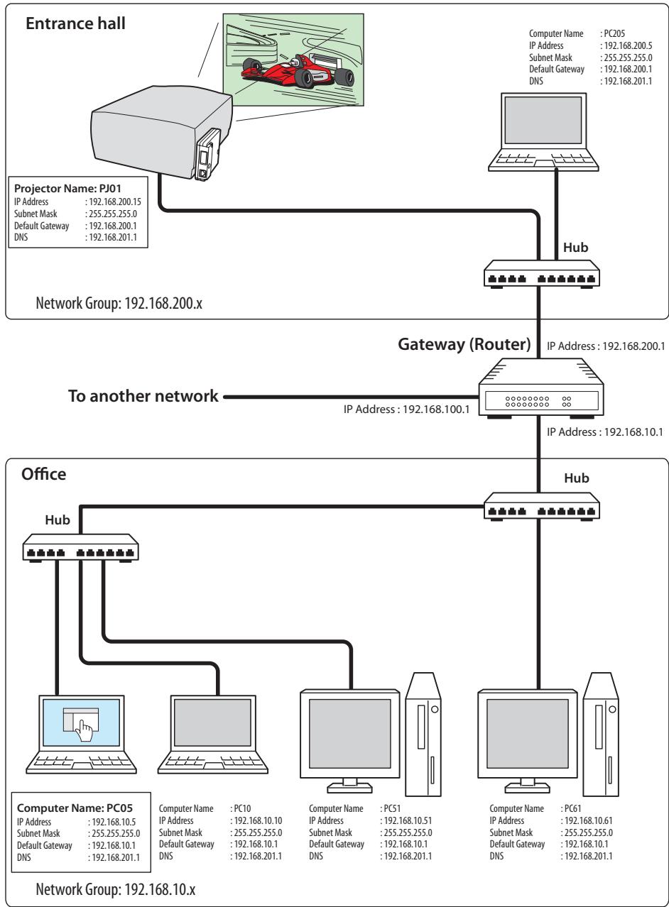
Web browser setting
This product is designed to enable the projector to be set up and controlled from an Internet web browser. Depending on the preference settings of the web browser, some control functions may not be available. Please make sure that the following functions are set up properly in the web browser.
Active Script/JavaScript enable
There are some control items used with the JavaScript function in the setting pages. If the web browser is set not to use this JavaScript function, it may not control the projector properly. In this case, the following warning message will be displayed on the top of the page. To enable the JavaScript, please see further instructions on the next page.
Flash Player enable
The setting page of this product contains the Flash contents. To display the setting page, the Adobe Flash Player version 6 or later is required to be installed on your computer. For further product information, see the Adobe homepage. (http:// www.adobe.com). Even if your computer provides the Adobe Flash Player and the setting page does not appear on the web browser, check that Flash Player Plug
In(Shockwave Flash) is installed and set up correctly. please see further instructions on the next page and it is depending on the web browser.
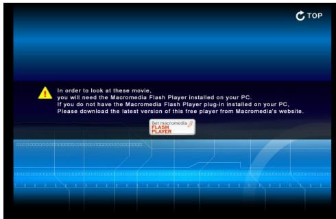
Proxy setting
In some cases, your web browser is set up to use the proxy server for the internet or intranet connection. In this case, when you install this product into the local network, you should set up the proxy setting of web browser preference correctly. Especially when connecting the projector and computer with a UTP cross cable directly, or when the network does not provide the proxy server, make sure that "not use proxy server" is set up in your web browser preference. Please see item "Examples: OS/Browsers" in the next page for further setting up procedure.
Examples: OS/Browsers
Windows XP Professional
Internet Explorer v.6.0
ActiveScript setting
Select Internet Options from Tools menu on the web browser and then select Security tab and click Customize Level... button. On the security setting window, scroll down and find the Scripting item, make sure that "Enable" is selected in item Active Scripting.
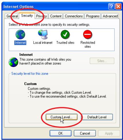
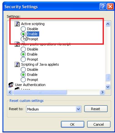
Flash Player enable
ActiveX controls and plug-ins setting
Select Internet Options from Tools menu on the web browser and then select Security tab and click Customize Level... button. On the security setting window, scroll down and find the ActiveX controls and Plug-ins item, make sure that "Enable" is selected in item Run ActiveX controls and plug-ins.
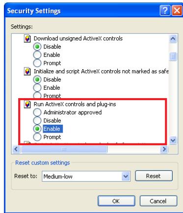
Flash Player Add-on setting
Select Manage Add-ons... from Tools menu on the web browser. Select "Add-ons currently located in Internet Explorer" from Show pull-down menu. Make sure that the "Shockwave Flash Object" is listed under the item "Enabled".
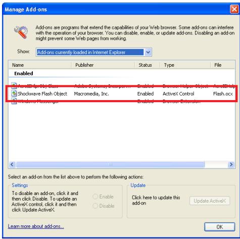
Proxy setting
Select Internet Options from Tools menu on the web browser and then select Connection tab and click LAN Settings
button. Properly set up your web browser's the proxy server settings according to the local area network environment to which the projector is connected.
- Using proxy server
To use an external internet connection from the local area network, check the item Use a proxy server and enter the proxy server address and port correctly in the proxy settings window. For further instruction please consult your network administrator.
- Not using proxy server
Uncheck the item Use a proxy server.
If you connect the projector to the computer directly with UTP cross cable, this must be unchecked.
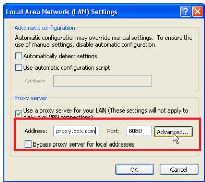
To designate proxy settings that will not use the proxy server when accessing the projector installed in the local area network, enter the IP address or domain name here.
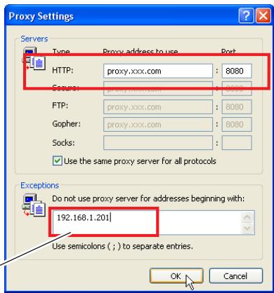
Netscape Navigator v.7.0
JavaScript Setting
Select Preference from Edit menu on the web browser and then select the item Advanced/Scripts & Plugins in the Category column. Make sure that the Enable JavaScript for Navigator is checked.
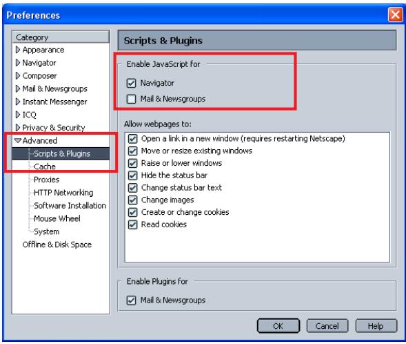
Flash Player enable
Flash Player Plug-in setting
Select About:Plug-ins from Help menu on the web browser. The plug-ins software provided on the browser are listed on the page. Check that the Flash Player Plugin (Shockwave Flash) is installed and set up correctly as the below.
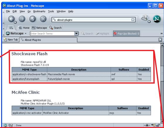
Shockwave Flash
File name: npswf32.dll
Shockwave Flash 7.0 r19
| MIME Type | Description | Suffixes | Enabled |
| application/x-shockwave-flash | Macromedia Flash movie | swf | Yes |
| application/futuresplash | FutureSplash movie | spl | Yes |
Proxy setting
Select Preference from Edit menu on the web browser and then select the item Advanced/ Proxies in the Category column. Properly set up your web browser's the proxy server settings according to the local area network environment to which the projector is connected.
- Using proxy server
When you use an external internet connection from the local area network, select the item Manual proxy configuration. Enter the proxy server address and port number correctly on HTTP Proxy item. For further instruction please consult your network administrator.
- Not using proxy server
Select the item Direct connection to the Internet in the proxy setting window.
If you connect the projector to the computer directly with UTP cross cable, this must be selected.
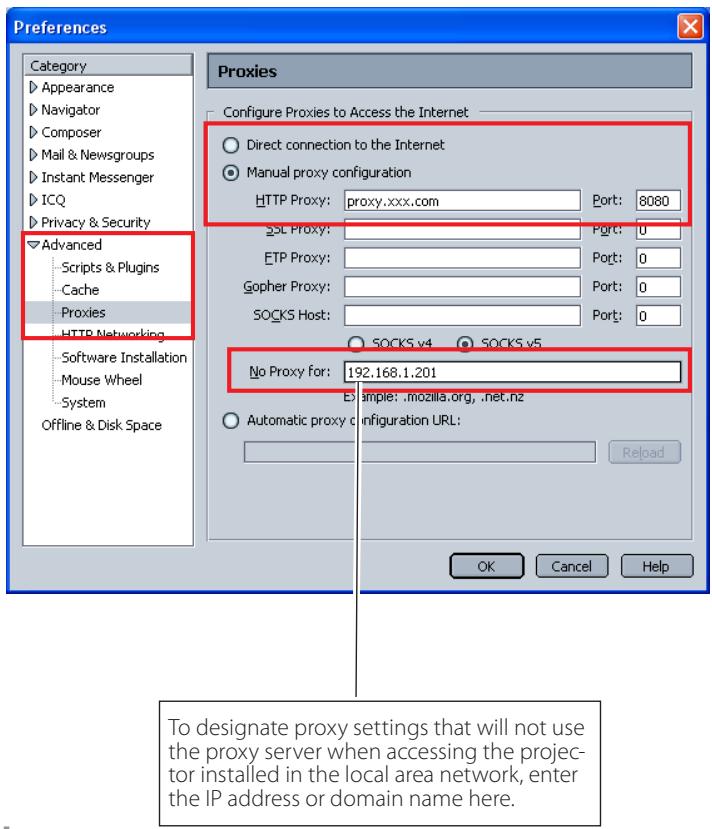
Product specification
Type............PJ-Net Organizer (network unit)
LAN interface............Applicant regulation IEEE802.3 (10Base-T)
IEEE802.3u (100Base-TX)
Data transfer speed 10Mbps/100Mbps
Data transfer mode Half duplex/Full Duplex
Terminal 8-pin modular (RJ-45)
Network protocol.....................................................TCP/IP specification TCP/IP
Power source.. Supplied from the projector
Power consumption 3.0 watts
Dimensions (W x H x D) 5.20" x 4.13" x 1.32" (132 x 105 x 33.6 x mm)
Weight 0.57 lbs (258 g)
Built-in battery............Lithium battery, Type CR2032, 3.0V
Operating temperature 41°F ~ 95°F (5°C ~ 35°C)
Storage temperature. 14^ 140^ (-10^ 60^)
- The specifications are subject to change without notice.
Port specification
LAN port specification
8-pin modular connector (RJ-45)
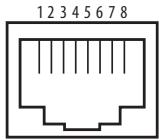
| Pin No. | Signal | Function |
| 1 | TX+ | Transfer data (+) |
| 2 | TX- | Transfer data (-) |
| 3 | RD+ | Receive data (+) |
| 4 | (not used) | |
| 5 | (not used) | |
| 6 | RD- | Receive data (-) |
| 7 | (not used) | |
| 8 | (not used) |
Q&A
Installation/Access

Why doesn't the setting page appear in my web browser?
A
Following causes are possible. Please check them.
- The projector does not connect to the network.
Check LED indicators status (p.17). - Check the connection of LAN cable if the LINK indicator does not illuminate red.
- Check the network configuration of the projector if ACT indicator does not illuminate green.
- Function "Network" in the projector is not set to "ON".
Set up by using the projector's on-screen menu (p.20). - Wrong network configuration of the projector
Check the network configuration of the projector by using the projector's on-screen menu (p.20). - Wrong network configuration of the computer.
Check the network configuration of the computer. - The network unit is used with the default setting (p.20).
- The proxy setting of the web browser is not set correctly (p.108).
- The computer does not provide TCP/IP protocol.

No setting page in my web browser? Is the problem in the network or in the projector? I would like to find out the problem whether it is in the network or in the projector
A
Check it by the following steps
- Disconnect the projector from the network and connect the projector and computer with the UTP cross cable directly.
- Change network configuration of the computer and projector as shown in the example below.
| (Projection setting) | (Computer setting) | ||
| IP Address | : 192.168.0.2 | IP Address | : 192.168.0.5 |
| Subnet Mask | : 255.255.255.0 | Subnet Mask | : 255.255.255.0 |
| Default gateway | : 0.0.0.0 | Default gateway | : (blank) |
| DNS | : 0.0.0.0 | DNS | : (blank) |
- Enter the projector's IP address [192.168.0.2] at "Address" column on the Web browser. [Note] Make sure that the proxy setting of your web browser is set "Not use a proxy server" (p.108).
- If the login page appears, this product is operating properly. The problems may be in the network configuration of the computer or in the network. Please try to set up the network by following item "Network configuration" (p.20). If the login page does not appear, please check for proper mounting of this product onto the projector by referring to chapter "Installation and Network configuration" (p.18-19).

How can I restrict access from the computer.

- Please use the password authentication function on the login page (p30).
- Please use the IP filtering function provided with the gateway (router) to restrict the accessing from the computer. For further information please consult your network administrator.

Can I access the projector installed on the company's local area network from a remote location?

There are some ways to access to the projector in the LAN, but you must consult your network administrator for security reason.
Use of modem
(Connect to the company's network from your home or some other places by using modem.)
Use of private line
(Connect to the company's network from the branch office or maintenance office by using private line.)
Use of internet
(Connect to the company's network from your home, branch office or some other places by using the internet.)

We use the DHCP/BOOTP server to assign the IP address. Is it possible to use the network unit in this network environment?

Possible. As the network unit does not support the DHCP/BOOTP server, the fixed IP address must be configured manually. Please consult your network administrator (p.24).
Q How can I install several projectors equipped with the network unit?
A Install and configure network one by one to avoid the IP address collision each other (p.24).
To configure the IP address please see item "Network configuration" (p.20).
Q How many projectors can I control with multi-control function?
A It has been designed to control up to 100 sets but it depends on the network environ
Password/Login
Q What should I do when I forget the password?
A Select "Network PIN code" sub menu from "Network" menu on the projector. For further information, please see item "Network PIN code setting" (p. 22).
Q Can I register the setting page as a web browser "Favorites" or "Bookmarks"?
A Please add "Login" page to your "Favorites" or "Bookmarks". Do not add the specified setting page because it will not be able to perform the password authentication cor- rectly.
Operation

Why can't I change the controls in the setting page with web browser?

Please make sure the projector is turned on. If it is in the standby mode, the setting is not effective to the projector. To control the projector with a web browser, the projector must be in the powered-on condition. Also, projectors registered for multi-control cannot have any controls changed if they are in standby mode. But timer and clock settings are always effective, even for projectors in standby mode.

Why does it sometimes take a lot of time to complete the page display?

The display speed of the page depends on the network environment in which both the projector and computer are placed. It may take much time to complete the page display if network traffic is heavy. Please consult your network administrator. You can select the Light mode for displaying pages quickly (p.30).

I use many of the projectors in the network. How can I use names of the projectors to recognize each projector instead of IP addresses?

You can manage the projectors with nicknames instead of the IP address. Please see item "Multi-control" for further information (p.62).
By registering the projector name and IP address with the DNS server, it can be accessed with the nickname from the any computer referred to the DNS server. Please consult your network administrator.

How many numbers of the E-mail address can I register in the E-mail setting page.

You can register up to 10 addresses.

Why am I not receiving E-mail alert messages?

Make sure that the registered E-mail address and SMTP server address are correct. If the SMTP server is located in your LAN (Local Area network), the address should be set to the SMTP server in your LAN. The SMTP server located outside of your LAN may not be available for security reason. For further information please contact your network administrator (p38).
It may be required for the authentication depending on the SMTP server. This product does not support this kind of SMTP server.

Can I update the firmware of the network unit.

It is possible to update the firmware through the network. It is required to have a special tool for the updating. For further information please consult your local dealer. The version number of the firmware is indicated on the lower part of the "Initial setting" page.
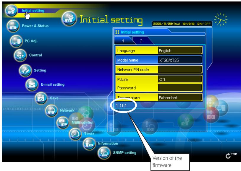

What are the rules for IP address assignment?

If the network is constructed with TCP/IP protocol, a unique IP address is required for each piece of network equipment. The following are basic rules of the assignment.
Rule1
Do not configure the same IP address to the network equipment in the same network group. Each piece of equipment must be assigned a unique IP address.
If the IP address is set [192.168.x.x], the Subnet Mask should be set [255.255.255.0] for example.
Rule2
The start address [xxx.xxx.xxx.0] and the last address [xxx.xxx.xxx.255] of the IP address must not be assigned to any other equipment. These address numbers are reserved.
Rule3
The IP address must correlate to a network number. If network numbers are different between the equipment, they cannot establish communications each other. In this case, the router is placed in the networks to make the routing.

What is the MAC address assigned to the network unit?

The MAC address is indicated on the case back as the below.
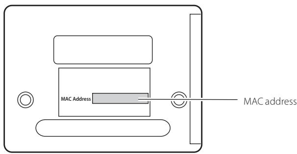
Network capture

Why doesn't the computer screen appear on the projected screen?

- Make sure that the input mode of the projector is "Network".
- Make sure that the Network Capture icon on the task bar of the computer is active (p.70).
- Check the parameter set up (p.71). Make sure that the numbers of the capture port is the same as the projector's port number. The default port number is 9000. If the alert message "Invalid Port No." appears, your computer may be using this port number already. In this case, use another port number.
- Check the IP address of the computer is registered to the network unit correctly (p. 72).
- Make sure that your computer is not using the firewall function. The network unit may not be able to use the port due to this firewall function. In this case, please turn off this function temporarily. There are also some port limitations on the network equipment such as router. Please consult your network administrator.
Network Viewer

Images from the file server don't appear on the screen?

-
Make sure that the input mode of the projector is "Network".
-
Check the account setting of the FTP server (p.99).
- The files in the FTP server must be optimized JPEG and converted by using the File Converter 1 or 2. Please check data format. (R p.89)
- There are several limitations for image file name and program name. Please check file names and program names (p97).
- Make sure that your computer is not using the firewall function. The network unit may not be able to use the port due to this firewall function. In this case, please turn off this function temporarily. There are also some port limitations on the network equipment such as router. Please consult your network administrator.

I cannot make a new program file.

Check your account of the FTP server. You must have a mode "Write enable" for its account.(p.93)
File Converter 1

What kind of image formats can I convert?

The File Converter 1 enables to convert to the JPEG format from the following image format.
Bitmap format (.bmp)
JPEG format (.jpeg.jpg)
Microsoft power point format (.ppt)
File Converter 2

Sometime I have the white frame images converted by the File Converter 2?

It may have images with white frame due to the paper margin of the print driver depending on the image data.