
PIKE II 3108-8i-16PD/2G - Controller ASUS - Free user manual and instructions
Find the device manual for free PIKE II 3108-8i-16PD/2G ASUS in PDF.


| Product Type | RAID Controller |
| Brand | ASUS |
| Model | PIKE II 3108-8i-16PD/2G |
| Chipset | LSI SAS 3108 Dual-Core |
| Host Bus Interface | PCI Express 3.0 x8 |
| SAS Ports | 8 internal (12 Gbps) |
| Supported Devices | Up to 16 SAS or SATA drives |
| Cache Memory | 2 GB DDR3 |
| RAID Levels | 0, 1, 5, 6, 10, 50, 60, JBOD |
| Connectors | 2 x SFF-8643 (Mini-SAS HD) |
| Form Factor | Low-profile MD2 (half-height) |
| Dimensions | 6.6 x 2.5 x 0.7 inches (approx) |
| Weight | 0.44 lb (200 g) |
| Power Consumption | 15W (typical) |
| Operating Temperature | 0°C to 55°C |
| Storage Temperature | -40°C to 70°C |
| Relative Humidity | 10% to 90% non-condensing |
| Operating Systems | Windows Server, Linux (Red Hat, SUSE, Ubuntu), VMware ESXi, FreeBSD |
| Data Transfer Rate | Up to 12 Gbps per port |
| Advanced Features | Online Capacity Expansion, RAID Level Migration, FastPath, CacheCade |
| Management | StorCLI, MegaRAID Storage Manager |
| Compliance | CE, FCC, RoHS |
| Cooling | Passive heatsink (requires airflow) |
| Warranty | 3 years |
Frequently Asked Questions - PIKE II 3108-8i-16PD/2G ASUS
User questions about PIKE II 3108-8i-16PD/2G ASUS
0 question about this device. Answer the ones you know or ask your own.
Ask a new question about this device
Download the instructions for your Controller in PDF format for free! Find your manual PIKE II 3108-8i-16PD/2G - ASUS and take your electronic device back in hand. On this page are published all the documents necessary for the use of your device. PIKE II 3108-8i-16PD/2G by ASUS.
USER MANUAL PIKE II 3108-8i-16PD/2G ASUS
E13674
Revised Edition V3
December 2017
Copyright © 2017 ASUSTeK COMPUTER INC. All Rights Reserved.
No part of this manual, including the products and software described in it, may be reproduced, transmitted, transcribed, stored in a retrieval system, or translated into any language in any form or by any means, except documentation kept by the purchaser for backup purposes, without the express written permission of ASUSTeK COMPUTER INC. ("ASUS").
Product warranty or service will not be extended if: (1) the product is repaired, modified or altered, unless such repair, modification of alteration is authorized in writing by ASUS; or (2) the serial number of the product is defaced or missing.
ASUS PROVIDES THIS MANUAL "AS IS" WITHOUT WARRANTY OF ANY KIND, EITHER EXPRESS OR IMPLIED, INCLUDING BUT NOT LIMITED TO THE IMPLIED WARRANTIES OR CONDITIONS OF MERCHANTABILITY OR FITNESS FOR A PARTICULAR PURPOSE. IN NO EVENT SHALL ASUS, ITS DIRECTORS, OFFICERS, EMPLOYEES OR AGENTS BE LIABLE FOR ANY INDIRECT, SPECIAL, INCIDENTAL, OR CONSEQUENTIAL DAMAGES (INCLUDING DAMAGES FOR LOSS OF PROFITS, LOSS OF BUSINESS, LOSS OF USE OR DATA, INTERRUPTION OF BUSINESS AND THE LIKE), EVEN IF ASUS HAS BEEN ADVISED OF THE POSSIBILITY OF SUCH DAMAGES ARISING FROM ANY DEFECT OR ERROR IN THIS MANUAL OR PRODUCT.
SPECIFICATIONS AND INFORMATION CONTAINED IN THIS MANUAL ARE FURNISHED FOR INFORMATIONAL USE ONLY, AND ARE SUBJECT TO CHANGE AT ANY TIME WITHOUT NOTICE, AND SHOULD NOT BE CONSTRUED AS A COMMITMENT BY ASUS. ASUS ASSUMES NO RESPONSIBILITY OR LIABILITY FOR ANY ERRORS OR INACCURACIES THAT MAY APPEAR IN THIS MANUAL, INCLUDING THE PRODUCTS AND SOFTWARE DESCRIBED IN IT.
Products and corporate names appearing in this manual may or may not be registered trademarks or copyrights of their respective companies, and are used only for identification or explanation and to the owners' benefit, without intent to infringe.
Contents
Contents......iii
About this guide....v
PIKE II 3108 Series specifications summary ...... vii
Chapter 1: Product Introduction
1.1 Welcome! 1-2
1.2 Package contents 1-2
1.3 Card layout 1-3
1.3.1 Switch settings 1-4
1.4 System requirements....1-5
1.5 Card installation....1-6
Chapter 2: RAID Configuration
2.1 Setting up RAID....2-2
2.1.1 RAID definitions 2-2
2.1.2 Installing hard disk drives....2-3
2.2 MegaRAID Configuration Utility....2-3
2.2.1 Starting the MegaRAID Configuration Utility 2-4
2.2.2 MegaRAID Configuration Utility 2-5
2.2.3 VD Mgmt Menu 2-7
2.2.4 PD Mgmt Menu 2-8
2.2.5 Ctrl Mgmt Menu.... 2-9
2.2.6 Properties Menu....2-10
2.2.7 Foreign View Menu....2-11
2.2.8 Managing Software Licensing....2-12
2.2.9 Creating a Storage Configuration.... 2-13
2.2.10 Selecting Additional Virtual Drive Properties 2-14
2.2.11 Modifying Controller Properties....2-17
2.2.12 Viewing and Changing Virtual Drive Properties 2-20
2.2.13 Deleting a Virtual Drive 2-20
2.2.14 Deleting a Virtual Drive Group 2-21
2.2.15 Initializing a Virtual Drive....2-21
2.2.16 Running a Consistency Check....2-22
2.3 MegaRAID Storage Manager 2-23
2.3.1 Hardware and Software Requirements....2-23
2.3.2 Installing MegaRAID Storage Manager Software on Microsoft Windows OS....2-23
2.3.3 Installing MegaRAID Storage Manager Software for Linux...... 2-27
2.3.4 Linux Error Messages 2-28
2.3.5 Starting the MegaRAID Storage Manager Software 2-29
2.3.6 MegaRAID Storage Manager Window 2-31
Chapter 3: Driver Installation
3.1 RAID driver installation 3-2
3.1.1 Windows ® Server 2012 R2 OS....3-2
3.1.2 Red Hat ® Enterprise Linux OS 7.0....3-4
3.1.3 SUSE Linux OS 12....3-6
Simplified EU Declaration of Conformity 3-8
ASUS contact information....3-9
About this guide
This user guide contains the information you need when installing and configuring the server management board.
How this guide is organized
This guide contains the following parts:
• Chapter 1: Product Introduction
This chapter offers the PIKE II 3108 SAS RAID card features and the new technologies it supports.
• Chapter 2: RAID Configuration
This chapter provides instructions on setting up, creating, and configuring RAID sets using the available utilities.
• Chapter 3: Driver Installation
This chapter provides instructions for installing the RAID drivers on different operating systems.
Where to find more information
Refer to the following sources for additional information and for product and software updates.
- ASUS websites
The ASUS website provides updated information on ASUS hardware and software products. Refer to the ASUS contact information.
- Optional documentation
Your product package may include optional documentation, such as warranty flyers, that may have been added by your dealer. These documents are not part of the standard package.
Conventions used in this guide
To make sure that you perform certain tasks properly, take note of the following symbols used throughout this manual.

DANGER/WARNING: Information to prevent injury to yourself when trying to complete a task.

CAUTION: Information to prevent damage to the components when trying to complete a task.

IMPORTANT: Instructions that you MUST follow to complete a task.

NOTE: Tips and additional information to help you complete a task.
Typography
Bold text Indicates a menu or an item to select.
Italics Used to emphasize a word or a phrase.
Example:
Example:
Command Means that you must type the command exactly as shown, then supply the required item or value enclosed in brackets.
Example: At the DOS prompt, type the command line:
format a:
PIKE II 3108 Series specifications summary
| PIKE II 3108-8i/16PD | PIKE II 3108-8i/240PD | PIKE II 3108-4i4e/240PD | |
| Controller | LSI SAS 3108 | ||
| Interface | PCI-E Gen 3 | ||
| Ports | 8 SAS 12Gb/s Ports (2 Mini-SAS HD SFF-8643) 8 SAS | 12Gb/s Ports(1 Mini-SAS HD SFF-8643 + 1 Mini-SAS HD SFF-8644) | |
| Support Device | SAS / SAS II /SAS 12Gb/s devicesSATA II / SATA III devices | ||
| Data transfer rate | SAS 12Gb/s | ||
| RAID Support | RAID 0/1/10/5/50/6/60 | ||
| Max. PHD | Max. physical Disk qty for RAID: 16 | Max. physical Disk qty for RAID: 240 | |
| Cache | 1GB on board SDRAM | ||
| Battery Backup Support | Header reserved for LSI CacheVault(acquired from LSI existing distribution channel) | ||
| Form factor | Standard low profile | ||

Only supports ASUS Z10,Z9,P9 motherboards/systems.
* The exact OS support would base on the OS support list of the motherboard.
** Specifications are subject to change without notice.
Product Introduction
1
This chapter offers the PIKE II 3108 SAS RAID card features and the new technologies it supports.
1.1 Welcome!
Thank you for buying an ASUS® PIKE II 3108 Series SAS RAID card!
The ASUS PIKE II 3108 Series SAS RAID card supports 12 Gb/s SAS Technology and allows you to create RAID 0, RAID 1, RAID 10, RAID 5, RAID 50, RAID 6, and RAID 60 sets from SATA II/SATA III/SAS/SAS II/SAS III hard disk drives connected to the SAS connectors on the card.
Before you start installing the RAID card, check the items in your package with the list below.
1.2 Package contents
Check your package for the following items:
• ASUS PIKE II 3108 Series SAS RAID card
- Support DVD

If any of the above items is damaged or missing, contact your retailer.
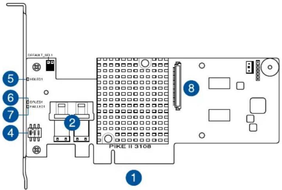
1.3 Card layout
The illustration below shows the major components of the RAID card.
PIKE II 3108-8i
PIKE II 3108-4i4e
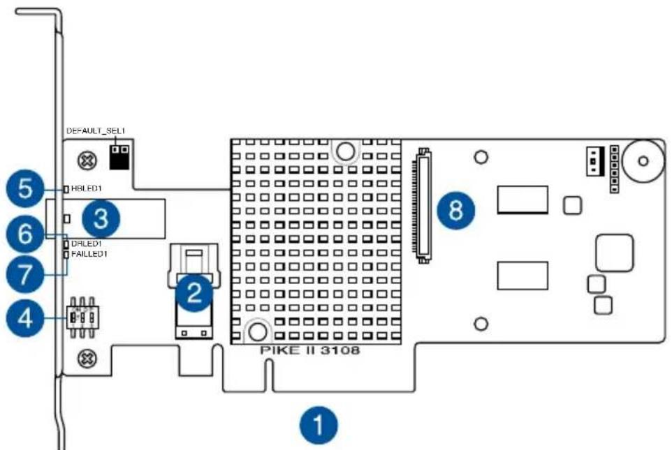
- PCI-E x8 interface
- Internal mini-SAS HD connectors
- External mini-SAS HD connector
- Switch* (for more than one card)
-
HBLED1 (HEARTBEAT LED): The LED shows the firmware heartbeat information (blinking)
-
DRLED1 (Dirty cache LED): Write Pending (light)
- FAILLED1 (Global Drive Fault LED): Drive fault detected (light)
- CacheVault connector
1.3.1 Switch settings
When using more than one PIKE II card on your system, ensure to manually set the pin settings on the Switch on each of the PIKE II cards to ensure that the system detects all the cards installed. You can refer to the following table for the pin settings.

PIKE II card Switch pin settings and recommended configuration:
| PIKE 3108 | Switch Pin name Pin value | |
| 1 SW1 [1:2:3] | 111 | |
| 2 SW1 [1:2:3] | 110 | |
| 3 SW1 [1:2:3] | 101 | |
| 4 SW1 [1:2:3] | 100 | |
| 5 SW1 [1:2:3] | 011 | |
| 6 SW1 [1:2:3] | 010 | |
| 7 SW1 [1:2:3] | 001 | |
| 8 SW1 [1:2:3] | 000 |
1.4 System requirements
Before you install the PIKE II 3108 Series RAID card, check if the system meets the following requirements:
• ASUS Server motherboard
- PCI-E Gen3 slot
• SAS or SATA hard disk drives
- Mini-SAS HD cable
• Supported operating system:
- Windows ® and Linux operating systems (refer to website for details)
• Other requirements:
- Appropriate thermal solution
- Certified power supply module

Ensure to update your BIOS to the latest version before using PIKE II 3108 series on ASUS Z9 or P9 series platform.
1.5 Card installation
To install the RAID card on your motherboard:
- Locate the PCIE Gen3 slot on the motherboard.
- Align the golden fingers of the PIKE card with the PCIE Gen3 card slot.
- Insert the RAID card into the PCIE Gen3 card slot. Ensure the card is completely seated in place.

- For PIKE II 3108-8i, connect the hard disk drives to the internal Mini-SAS HD connectors.
For PIKE II 3108-4i4e, connect the hard disk drives to the internal and external Mini-SAS HD connectors.

Internal mini-SAS HD connector
External mini-SAS HD connector
Internal mini-SAS HD connector

RAID Configuration
This chapter provides instructions on setting up, creating, and configuring RAID sets using the available utilities.
2
2.1 Setting up RAID
The RAID card supports RAID 0, 1, 10, 5, 50, 6, and 60.
2.1.1 RAID definitions
RAID 0 (Data striping) optimizes two identical hard disk drives to read and write data in parallel, interleaved stacks. Two hard disks perform the same work as a single drive but at a sustained data transfer rate, double that of a single disk alone, thus improving data access and storage. Use of at least two new identical hard disk drives is required for this setup.
RAID 1 (Data mirroring) copies and maintains an identical image of data from one drive to a second drive. If one drive fails, the disk array management software directs all applications to the surviving drive as it contains a complete copy of the data in the other drive. This RAID configuration provides data protection and increases fault tolerance to the entire system. Use two new drives or use an existing drive and a new drive for this setup. The new drive must be of the same size or larger than the existing drive.
RAID 10 is a striped configuration with RAID 1 segments whose segments are RAID 1 arrays. This configuration has the same fault tolerance as RAID 1, and has the same overhead for fault-tolerance as mirroring alone. RAID 10 achieves high input/output rates by striping RAID 1 segments. In some instances, a RAID 10 configuration can sustain multiple simultaneous drive failure. A minimum of four hard disk drives is required for this setup.
RAID 5 stripes both data and parity information across three or more hard disk drives. Among the advantages of RAID 5 configuration include better HDD performance, fault tolerance, and higher storage capacity. The RAID 5 configuration is best suited for transaction processing, relational database applications, enterprise resource planning, and other business systems. Use a minimum of three identical hard disk drives for this setup.
RAID 50 is a combination of RAID 0 and RAID 5. It uses distributed parity and disk striping and works best with data that requires high reliability, high request rates, high data transfers, and medium-to-large capacity.
RAID 6 uses distributed parity, with two independent parity blocks per stripe, and disk striping. A RAID 6 virtual drive can survive the loss of two drives without losing data. A RAID 6 drive group, which requires a minimum of three drives, is similar to a RAID 5 drive group. Blocks of data and parity information are written across all drives. The parity information is used to recover the data if one or two drives fail in the drive group.
RAID 60, a combination of RAID 0 and RAID 6, uses distributed parity, with two independent parity blocks per stripe in each RAID set, and disk striping. A RAID 60 virtual drive can survive the loss of two drives in each of the RAID 6 sets without losing data. It works best with data that requires high reliability, high request rates, high data transfers, and medium-to-large capacity.

- Having RAID 0 and RAID 5 virtual disks in the same physical array is not recommended. If a drive in the physical array has to be rebuilt, the RAID 0 virtual disk will cause a failure during the rebuild.
- If you want to boot the system from a hard disk drive included in a created RAID set, copy first the RAID driver from the support CD to a floppy disk before you install an operating system to the selected hard disk drive.
2.1.2 Installing hard disk drives
The RAID card supports SAS for RAID set configuration. For optimal performance, install identical drives of the same model and capacity when creating a disk array.
To install SAS hard disks for RAID configuration:
- Install the SAS hard disks into the drive bays following the instructions in the system user guide.
- Connect a SAS signal cable to the signal connector at the back of each drive and to the SAS connector on the motherboard.
- Connect a power cable to the power connector on each drive.
2.2 MegaRAID Configuration Utility
The AVAGO MegaRAID SAS-MFI BIOS Utility is an integrated RAID solution that allows you to create RAID 0, 1, 10, 5, 50, 6, and 60 sets from SATA II/SATA III/SAS/SAS II/SAS III hard disk drives supported by the LSI SAS 3108 12Gb/s SAS controller.
- Create drive groups and virtual drives for storage configurations
- Delete virtual drives
- Migrate a storage configuration to a different RAID level
- Detect configuration mismatches
- Import a foreign configuration
- Display controller, virtual drive, physical drive, and change parameters.
- Scan devices connected to the controller
- Initialize virtual drives
- Check configurations for data consistency
- Create a CacheCade™ configuration

- You may use disks of different sizes; however, the size of the smallest disk determines the "logical" size of each member disk.
- DO NOT combine Serial ATA and SAS disk drives in one volume.
- The RAID setup screens shown in this section are for reference only and may not exactly match the items on your screen due to the controller version difference.
2.2.1 Starting the MegaRAID Configuration Utility
Follow these steps to start the MegaRAID Configuration Utility and access the main screen.
- Turn on the system after installing all SAS hard disk drives.
- During POST, press
AVAGO MegaRAID SAS-MFI BIOS
Version 6.25.01.0 (Build February 20, 2015)
Copyright(c) 2015 AVAGO Technologies
F/W Initializing Devices 100%
HA -0 (Bus 2 Dev 0) Asustek PIKE 3108-8i
Battery Status: Missing
PCI Slot Number: 6

ID LUN VENDOR PRODUCT REVISION CAPACITY
--- --- --- ---
AVAGO Asustek PIKE 3108-8i 4.298.00-4168 1024MB
0 0 SEAGATE ST3300657SS 0008 286102MB
1 0 SEAGATE ST3300657SS 0006 286102MB
2 0 SEAGATE ST3300657SS 0006 286102MB
3 0 SEAGATE ST3300657SS 0008 286102MB

0 Virtual Drive(s) found on the host adapter.
0 Virtual Drive(s) handled by BIOS

Press <Ctrl><R> to Run MegaRAID Configuration Utility
- If the system has multiple SAS controllers, a controller selection dialog appears. Select a controller and press
.
2.2.2 MegaRAID Configuration Utility
The integrated RAID solution allows you to create the following RAID sets from SAS hard disk drives supported by the LSI SAS 3108 12Gb/s SAS controller: RAID 0, 1, 10, 5, 50, 6, and 60.

- You may use disks of different sizes in one volume; however, the size of the smallest disk determines the "logical" size of each member disk.
• DO NOT combine Serial ATA and SAS disk drives in one volume.

- The RAID setup screens shown in this section are for reference only and may not exactly match the items on your screen due to the controller version difference.
- The adapter name shown on the setup screens differs according to the installed SAS RAID card.
MPTFW and MPTBIOS version of the SAS RAID card
Take note of the BIOS and FW version of your SAS RAID card. You will need it if you request support from the ASUS Technical Support team.
You can get the BIOS and FW version of your SAS RAID card, navigate to the Properties screen.

Utility Keystrokes
| Keystroke Action | |
| F1 Displays help for the particular screen that you are in. | |
| F2 | Displays a list of commands that can be performed for the selected device. This key stroke is available only in the VD Mgmt, the PD Mgmt, and the Foreign View menus. The commands that are enabled are highlighted in white and the disabled commands are highlighted in black.NOTE: Based on the configurations that you make, commands are enabled or disabled. |
| F5 Refreshes | the screen that you currently are in. |
| F11 Switches | between controllers. |
| F12 | Displays a list of all the available controllers. You can also scroll to the next controller. |
| Displays the next menu screen. | |
| Displays the previous menu screen | |
| shortcut key for the Apply button in the Controller Settings screens. | |
| Moves the cursor to the next control. | |
| Lets you to select a menu item, a button, a check box and values in a list box. | |
| Closes a screen or a window. Press Esc twice to exit from the Ctrl-R Utility. | |
| Up Arrow Moves the cursor to the next menu selection. | |
| Down Arrow Moves the cursor to the lower menu items or to a lower level menu. | |
| Right Arrow | Opens a submenu, moves from a menu heading to the first submenu, or moves to the first item in a submenu. The right arrow also closes a menu list in a popup window. |
| Left Arrow | Closes a submenu, moves from a menu item to the menu heading or moves from a sub menu to a higher level menu. |
| Spacebar Lets you select a menu item, a button and a check box. | |
2.2.3 VD Mgmt Menu
This screen shows information on the configuration of controllers, drive groups, and virtual drives.
![Asustek PIKE 3108-81 BIOS Configuration Utility 5.10-0200 VD Mgmt PD Mgmt Ctrl Mgmt Properties Virtual Drive Management [-] Asustek PIKE 3108-81(Bus 0x02, Dev 0x00) No Configuration Present ! [-] Unconfigured Drives ---:---:04: Ready: 278.875 GB ---:---:05: Ready: 278.875 GB ---:---:06: Ready: 278.0…](/content/2026/05/965623/images/09c4b1514d4f3cf36d4559987c301605cdf49473e32d37eced7c9a4412dba2e0.jpg)
In the Virtual Drive Management screen, you can perform tasks, such as creating and initializing virtual drives; performing a consistency check; deleting, expanding, and erasing virtual drives; importing or clearing foreign configurations; and creating CacheCade virtual drives. The right panel of the screen shows attributes of the selected device.

Based on the controller settings, some options will be enabled or disabled.
2.2.4 PD Mgmt Menu
The PD Mgmt menu shows information about all the physical drives connected to the selected controller. This menu also shows information about enclosures, the number of physical drives in an enclosure, and all of the direct-attached drives under a backplane node.

In the Drive Management screen, you can perform tasks, such as rebuilding a failed drive, making a drive offline, or making it a global hot spare drive. The right panel of the screen shows additional attributes of the selected device.
2.2.5 Ctrl Mgmt Menu
The Ctrl Mgmt menu lets you change the settings of the selected controller. The Ctrl Mgmt menu consists of two screens.
![Asustek PIKE 3108-81 BIOS Configuration Utility 5.10-0200 VD Mgmt PD Mgmt Ctrl Mgmt Properties Controller Settings Alarm Control Enable Silence Coercion Mode: BIOS Mode: Boot device: None Safe Mode NONE Rebuild Rate: 30 Patrol Rate : 30 [X] Maintain PD Fail History BGI Rate : 30 Cache Flush Interval…](/content/2026/05/965623/images/ad0c97917435d19375b629008ef657a92f8d80ef6f96a72266ed77d44dba7822.jpg)
In the first screen, you can change controller options, such as Enable Controller BIOS, Maintain PD Fail History, Enable JBOD, Auto Enhanced Import, and Enable Stop CC on Error. You also can perform tasks, such as enabling or silencing an alarm, entering values for Rebuild Rate and Patrol Rate, and enabling or disabling the JBOD mode. If you enable the JBOD mode, the drive comes up as JBOD; otherwise, the drive comes up as Unconfigured Good.

In the second screen, you can perform tasks, such as changing the link speed, the power save, and the battery settings of the controller.
2.2.6 Properties Menu
The Properties menu shows all of the properties of the active controller. The Properties menu consists of two screens. The information shown in these screens is read only.
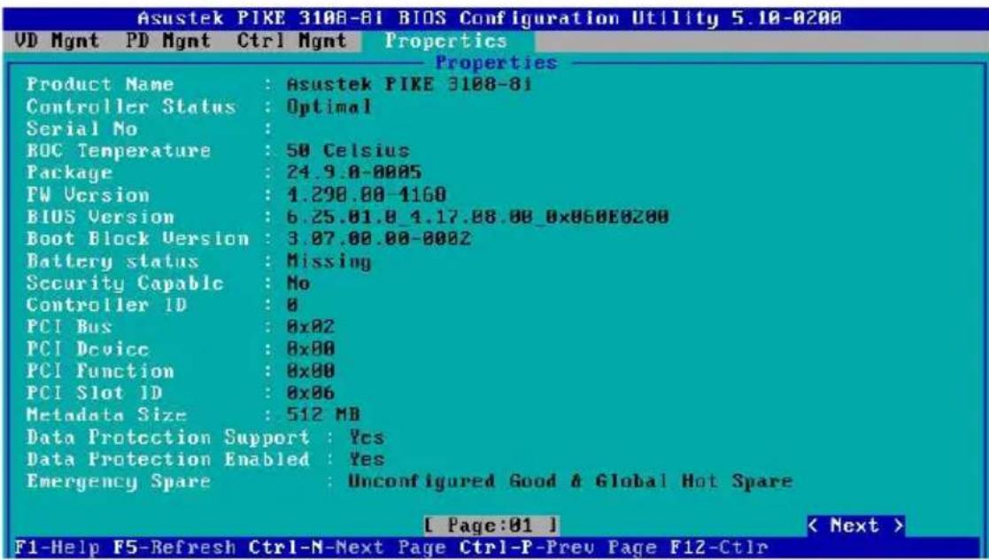
In the first screen, you can view properties, such as controller status, firmware version, BIOS version, and metadata size. To view additional properties, you can navigate to Next and press

The second Properties screen shows information, such as maximum cache size, drive standby time, and power saving properties. To go back to the previous Properties screen, navigate to Prev, and press
2.2.7 Foreign View Menu
The Foreign View menu is shown only when the controller detects a foreign configuration. If no foreign configurations exists, the Foreign View menu is not shown.
![Asustek PIKE 3100-8i BIOS Configuration Utility 5.10-8200 UD Mgmt PD Mgmt Ctrl Mgmt Properties Foreign View Foreign Config View [-] Asustek PIKE 3100-8i(Bus 8x82, Dev 8x80) [–] Drive Group: 0, Raid 1 (Foreign) [–] Virtual Drives ID: 0, 67.05 GB [+] Drives Hot spare Drives Foreign Config Preview Virt…](/content/2026/05/965623/images/9ffcc4ec3c4b2e0ebf9960986ac8bd006883a7155a75156211dc21bcaf094b77.jpg)
If one or more physical drives in a configuration are removed and reinserted, the controller considers the drives as foreign configurations.
You can use the Foreign Config View screen to view information about the foreign configuration, such as drive groups, virtual drives, physical drives, and hot spares. The Foreign View menu lets you import foreign configurations to the RAID controller or clear the foreign configurations.
2.2.8 Managing Software Licensing
The MegaRAID advanced software offers the software license key feature to enable the advanced options. The license key is also known as the activation key.
To configure the Advanced Software options by using the activation key:
- In the VD Mgmt screen, navigate to the controller and press the
key. - Navigate to Advanced Software Options, and press
. - Enter a valid activation key in the Activation Key field.

The Activated MegaRAID Advanced Software Options box contains the Adv SW Option and License columns.
- The Adv SW Option column shows the list of advanced software features available in the controller.
- The License column shows the license details for the list of advanced software options present in the Av SW Option column. The license details validates if the software is under trial period, or whether it can be used without any trial period (Unlimited).
2.2.9 Creating a Storage Configuration
You can configure RAID drive groups and virtual drives to create storage configurations on systems with LSI SAS controllers.
To create a storage configuration:
- In the VD Mgmt screen, navigate to the controller and press the
key. - Press
. The Create New VD screen appears.

You can use the Create New VD dialog to create virtual drives for Unconfigured Good drives. To create virtual drives for existing drive groups, navigate to a drive group and press the
![Asustek PIKE 3108-81 BIOS Configuration Utility 5.10-0200 UD Mgmt PD Mgmt Ctrl Mgmt Properties Create New UD RAID BAID-0 Data Disable Level: Protection: PD per Span : N/A Drives ID Type Size # Capable [ ]---:---:04 SAS 270.875 GB -- -- [ ]---:---:05 SAS 270.875 GB -- -- [ ]---:---:06 SAS 278.875 GB…](/content/2026/05/965623/images/dff84bcd684e695543756bbbc04695409e35db6fff2ccb28ab33e60eea49c2ee.jpg)
-
Select a RAID level for the drive group from the RAID Level field.
-
All the available unconfigured good drives appear in the Drives box. Select the physical drives that you prefer.
-
You can enter a size less than the maximum size of the drive group, if you want to create other virtual drives on the same drive group. The maximum size of the drive group appears in the Size field. Before entering a size, ensure that you have deleted the previous default value by using the
key. -
Enter a name for the virtual drive in the Name field. The name given to the virtual drive cannot exceed 15 characters.
-
Press OK.

Press Advanced to set additional properties. For more information, see the Selecting Additional Virtual Drive Properties section.
To initialize the virtual drive:
- Navigate to the Virtual Drive you just created.
- Press
and then choose one of the Initialization options.
![Asustek PIKE 3108-81 BIOS Configuration Utility 5.10-0200 VD Mgmt PD Mgmt Ctrl Mgmt Properties Virtual Drive Management [-] Asustek PIKE 3108-81(Bus 0x02, Dev 0x00) [−] Drive Group: 0, RAID 0 [−] Virtual Drives ID: 0, 1.088 TB [+] Drives [+] Available size: 0.000 Hot spare drives Initialization Cons…](/content/2026/05/965623/images/6ae6d2346999efc7b4305143518344a88670d28a8d84218cf6000ffc27a2277a.jpg)
2.2.10 Selecting Additional Virtual Drive Properties
This section describes the following additional virtual drive properties that you can select while you create virtual drives. Change these parameters only if you have a specific reason for doing so. It is usually best to keep them at their default settings.
![Asustek PIKE 3108-81 BIOS Configuration Utility 5.10-0200 UD Mgmt PD Mgmt Ctrl Mgmt Properties Create New UD RAID Level: Strip Size: 256KB [ ] Initialize Read Policy: Ahead [ ] Configure HotSpare Write Policy: Write Through I/O Policy: Direct OK Disk cache Unchanged Policy Cancel Enulation Default B…](/content/2026/05/965623/images/3ce11972384301fc551608cee08564e96e784be894b3ca55777a32b5c30bd293.jpg)
Strip Size – The strip size is the portion of the stripe that resides on a single virtual drive in the drive group. Strip sizes of 64 KB, 128 KB, 256 KB, 512 KB, or 1 MB are supported.
Read Policy – Specify one of the following options to specify the read policy for this virtual drive:
Normal – Read ahead capability lets the controller read sequentially ahead of requested data and to store the additional data in cache memory, thereby anticipating that the data will be needed soon. This process speeds up reads for sequential data, but there is little improvement when the computer accesses random data.
Ahead – Disables the read ahead capability.
Write Policy – Select one of the following options to specify the write policy for this virtual drive:
Write Thru – In this mode, the controller sends a data transfer completion signal to the host when the drive subsystem has received all the data in a transaction. This option eliminates the risk of losing cached data in case of a power failure.
Write Back – In this mode, the controller sends a data transfer completion signal to the host when the controller cache has received all the data in a transaction.
Write Back with BBU – In this mode the controller has no BBU or the BBU is bad. If you do not choose this option, the controller firmware automatically switches to the Write Thru mode if it detects a bad or missing BBU.

The write policy depends on the status of the BBU. If the BBU is not present, is low, is failed, or is being charged, the virtual drive is still in the Write Back mode and there is a chance of data loss.
I/O Policy – The I/O policy applies to reads on a specific virtual drive. It does not affect the read ahead cache.
Cached – In this mode, all reads are buffered in cache memory. Cached I/O provides faster processing.
Direct – In this mode, reads are not buffered in cache memory. Data is transferred to the cache and the host concurrently. If the same data block is read again, it comes from cache memory. Direct I/O makes sure that the cache and the host contain the same data.
Disk cache policy – Select a cache setting for this virtual drive:
Enable – Enable the drive cache.
Disable – Disable the drive cache.
Unchanged – Updating the drive cache policy to Unchanged may enable / disable the drive cache based on the WCE (Write Cache Policy) bit of the save mode page of the drive.
Emulation – Lets you to set the emulation type on a virtual drive to default or none. The force option forces the emulation to be set on a controller even when MFC settings do not support it. The possible options are Default, Disabled, or Forced.
Initialize – Select to initialize the virtual drive. Initialization prepares the storage medium for use. Fast initialization will be performed on the virtual drive.
Configure Hot Spare – Select to configure physical drives as hot spares for the newly created virtual drive.
This option is enabled only if there are additional drives and if they are eligible to be configured as hot spares. This option is not applicable for RAID 0. If you select this option and after the Virtual drive is created, a dialog appears. The dialog asks you to choose the physical drives that you want to configure as hot spares.
Provide shared access – Select this option if you want the virtual drive to be shared between the servers in a cluster. This option appears only if the controller supports High Availability DAS.
2.2.11 Modifying Controller Properties
The Utility shows information for one LSI SAS controller at a time. If your system has multiple LSI SAS controllers, you can view information for a different controller by pressing the
To change the controller properties:
- Navigate to the Ctrl Mgmt menu to view the first Controller Settings screen.
- You may change the values of the properties for the editable fields. To change additional properties, such as link speed, and power settings, press Next to go to the second Controller Settings screen.
- Press Apply. The following table describes all entries and options listed on both the Controller Settings screen. Leave these options at their default settings to achieve the best performance, unless you have a specific reason for changing them.
| Options Descriptions | |
| Alarm Control | Select this option to enable, disable, or silence the onboard alarm tone generator on the controller. |
| Coercion Mode | Use this option to force drives of varying capacities to the same size so they can be used in a drive group. The coercion mode options are None, 128MB-way, and 1GB-way. The number you choose depends on how much the drives from various vendors vary in their actual size. |
| BIOS Mode | Specifies the following options to set the BIOS boot mode:Stop on Error: shows the errors encountered during boot up and waits for your input. The firmware does not proceed with the boot process till you take some action.Ignore Error: Ignores errors and the firmware proceeds with boot.Pause on Error: the firmware may halt due to hardware faults. If the firmware encounters no hardware faults, then the boot up continues.SafeMode Error: Boots the controller to run on safe mode. |
| Boot Device | Use this option to select the boot device from the list of virtual drives and JBODs. |
| Rebuild Rate | Use this option to select the rebuild rate for drives connected to the selected controller. The rebuild rate is the percentage of system resources dedicated to rebuilding a failed drive. The higher the number, the more system resources that are devoted to a rebuild. The range of rebuild rate is between 0 and 100 percent. |
Options Descriptions
| BGI Rate | Use this option to select the amount of system resources dedicated to background initialization of virtual drives connected to the selected controller. The range of background initialization (BGI) rate is between 0 and 100 percent. |
| CC Rate | Use this option to select the amount of system resources dedicated to consistency checks of virtual drives connected to the selected controller. The range of Consistency Check (CC) rate is between 0 and 100 percent. |
| Recon. Rate | Use this option to select the amount of system resources dedicated to reconstruction of drives connected to the selected controller. The range of Recon rate is between 0 and100 percent. |
| Patrol Rate | Use this option to select the rate for patrol reads for drives connected to the selected controller. The patrol read rate is the percentage of system resources dedicated to running a patrol read. The range of patrol read is between 0 to 100 percent. |
| Cache Flush Interval | Use this option to control the interval at which the contents of the onboard data cache are flushed. The range of Cache Flush Interval is between 0 to100 seconds. |
| Spinup Delay | Use this option to control the interval (in seconds) between spinup of drives connected to this controller.The delay prevents a drain on the system's power supply that would occur if all drives spun up at the same time. The range of Spinup Delay is between 0 to 255 seconds. |
| Spinup Drive | Use this option to control the interval at which the contents of the onboard data cache are flushed. The range of Spinup Drive is between 0 to 255 seconds. |
| Maintain PD Fail History | Use this option to maintain the history of all drive failures. |
| Enable Controller BIOS | Use this option to enable or disable the BIOS for the selected controller.If the boot device is on the selected controller, the BIOS must be enabled. Otherwise, the BIOS should be disabled, or you might be unable to use a boot device elsewhere. |
| Enable Stop CC on Error | Use this option to stop a consistency check when the controller BIOS encounters an error. |
| Auto Enhanced Import | Use this option to import automatically at boot time. |
| Options Descriptions | |
| Set Factory Defaults | Set Factory Defaults |
| Manage Link Speed | Use this option to change the link speed between the controller and the expander, or between a controller and a drive that is directly connected to the controller |
| Manage Power Save | Use this option to reduce the power consumption of drives that are not in use, by spinning down the unconfigured good drives, hot spares and configured drives. |
| Manage Battery | Use this option to view information about the BBU, if the selected controller has a BBU. |
| Emergency Spare | Use this option to commission unconfigured good drives or global hotspares as emergency spare drives.You can select from the options None, UG (Unconfigured Good), GHS (Global Hotspare), orUGandGHS(Unconfigured Good and Global Hotspare). |
| Enable Emergency for SMARTer | Use this option to commission emergency hot spare drives for predictive failure analysis events. |
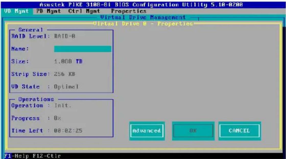
2.2.12 Viewing and Changing Virtual Drive Properties
The Utility shows the properties, policies, and the operations for virtual drives.
To view these items for the currently selected virtual drive and to change some of these settings:
- In the VD Mgmt screen, navigate to a virtual drive, and press the
key. - Press
.
2.2.13 Deleting a Virtual Drive
You can delete any virtual drive on the controller if you want to reuse that space for a new virtual drive. The Utility lists configurable drive groups where there is space to configure. If multiple virtual drives are defined on a single drive group, you can delete a virtual drive without deleting the entire drive group.

Back up any data that you want to keep before you delete a virtual drive.
To delete a virtual drive:
- In the VD Mgmt screen, navigate to a virtual drive, and press the
key. - Navigate to Delete VD, and press
. - Press OK to delete the virtual drive.
2.2.14 Deleting a Virtual Drive Group
You can delete a virtual drive group. On deleting a drive group, all the virtual drives in that drive group also are deleted.

Back up any data that you want to keep before you delete a virtual drive group.
To delete a virtual drive group:
- In the VD Mgmt screen, navigate to a virtual drive group, and press the
key. - Navigate to Delete Drive Group, and press
. - Press OK to delete the virtual drive group.
2.2.15 Initializing a Virtual Drive
When you create a new virtual drive, the Utility asks whether you would like to initialize the virtual drive. If you do not want to initialize the virtual drive at that stage, you can initialize the drive later.
To initialize a virtual drive:
- In the VD Mgmt screen, navigate to a virtual drive, and press the
key. - Navigate to Initialization, and press
. - Select one of the options, and press
. - Press Yes to begin initialization.

Initialization erases all data on the virtual drive. Make sure to back up any data you want to keep before you initialize a virtual drive. Make sure the operating system is not installed on the virtual drive you are initializing.
2.2.16 Running a Consistency Check
You should periodically run a consistency check on fault-tolerant virtual drives (RAID 1, 5, 6, 10, 50, or 60 configurations; RAID 0 does not provide data redundancy). A consistency check scans the virtual drive to determine whether the data has become corrupted and needs to be restored.

Make sure to back up the data before you run a consistency check, if you think the data might be corrupted.
To run a consistency check:
- In the VD Mgmt screen, navigate to a virtual drive, and press the
key. - Navigate to Consistency Check, and press
. - Navigate to Start, and press
. - Press Yes to run the consistency check.
2.3 MegaRAID Storage Manager
MegaRAID Storage Manager software enables you to configure, monitor, and maintain storage configurations on LSI SAS controllers. The MegaRAID Storage Manager graphical user interface (GUI) makes it easy for you to create and manage storage configurations.
2.3.1 Hardware and Software Requirements
The hardware requirements for MegaRAID Storage Manager software are as follows:
- PC-compatible computer with an IA-32 (32-bit) Intel Architecture processor or an EM64T (64-bit) processor and at least 128 Mb of system memory (256 Mb recommended)
- Disk drive with at least 50 Mb available free space
Refer to your server documentation and to the operating system documentation for more information on hardware and operating system requirements.
2.3.2 Installing MegaRAID Storage Manager Software on Microsoft Windows OS
Follow these steps if you need to install MegaRAID Storage Manager software on a system running Microsoft Windows OS:
- Insert the ASUS PIKE 3108 Support CD in the optical disc drive. The CD automatically displays the Utilities menu if Autorun is enabled in your computer.

If Autorun is NOT enabled in your computer, browse the contents of the Support CD to locate Setup.exe. Double-click Setup.exe to run the Support CD.
- Click LSI MegaRAID Storage Manager.
- When the Welcome screen appears, click Next.
If MegaRAID Storage Manager software is already installed on this system, the Program Maintenance screen appears. Read the screen text and select Modify, Repair, or Remove.
- When the next screen appears, read and accept the user license, and click Next.

-
Enter your user name and organization name. In the bottom part of the screen, select an installation option:
-
If you select All users, any user with administrative privileges can use this version of MegaRAID Storage Manager software to view or change storage configurations.
-
If you select Only for current user, the MegaRAID Storage Manager shortcuts and associated icons will be available only to the user with this user name.
-
Click Next to continue.
-
On the next screen, accept the default Destination Folder, or click Change to select a different destination folder. Click Next to continue.
The Setup Type screen appears, as shown in the following figure.

-
Select one of the Setup options. The options are fully explained in the screen text.
-
Normally, you would select Complete if you are installing MegaRAID Storage Manager software on a server.
-
Select Custom Installation if you want to select individual program components.
-
Click Next to continue.
If you selected Custom Installation as your setup option, the second Setup Type screen appears, as shown in the following figure.
If you select Complete as your setup option, the Installation Wizard is ready to install MSM. To begin installation, click on Install on the next screen that appears.

-
Select one of the custom setup options. The options are fully explained in the screen text.
-
Select Client if you are installing MegaRAID Storage Manager software on a PC that will be used to view and configure servers over a network. To begin installation, click on Install on the next screen that appears.
- Select Server to install only those components required for remote server management. To begin installation, click on Install on the next screen that appears.
- Select StandAlone if you will use MegaRAID Storage Manager software to create and manage storage configurations on a standalone workstation. To begin installation, click on Install on the next screen that appears.
- Select Custom if you want to specify individual program features to install.
If you select Custom, a window listing the installation features appears, as shown in the following figure. Select the features you want on this screen.

- Click Next to proceed.
- Click Install to install the program.
- When the final Configuration Wizard screen appears, click Finish.
If you select Client installation for a PC used to monitor servers, and if there are no available servers with a registered framework on the local subnet (that is, servers with a complete installation of MegaRAID Storage Manager software), the server screen appears, as shown in the following figure. The server screen will not list any servers. You can use this screen to manage systems remotely.

2.3.3 Installing MegaRAID Storage Manager Software for Linux
Follow these steps if you need to install MegaRAID Storage Manager software on a system running Red Hat Linux or SUSE Linux:
- Copy the MSM_linux_installer...tar.gz file to a temporary folder.
- Untar the MSM_linux_installer...tar.gz file using the following command:
tar -zxvf MSM_linux_installer...tar.gz
A new disk directory is created.
- Go to the new disk directory.
-
In the disk directory, find and read the readme.txt file.
-
To start the installation, enter the following command:
csh install.sh -a
If you select Client installation for a PC used to monitor servers, and if there are no available servers with a registered framework on the local subnet (that is, servers with a complete installation of MegaRAID Storage Manager software), the server screen appears. The server screen does not list any servers. You can use this screen to manage systems remotely.
2.3.4 Linux Error Messages
The following messages may appear while you are installing MegaRAID Storage Manager software on a Linux system:
- More than one copy of MegaRAID Storage Manager software has been installed.
This message indicates that the user has installed more than one copy of MegaRAID Storage Manager software. (This can be done by using the rpm-force command to install the rpm file directly, which is not recommended, instead of using the install.sh file.) In such cases, the user must uninstall all the rpm files manually before installing MegaRAID Storage Manager software with the procedure listed previously.
• The version is already installed.
This message indicates that the version of MegaRAID Storage Manager software you are trying to install is already installed on the system.
• The installed version is newer.
This message indicates that a version of MegaRAID Storage Manager software is already installed on the system, and it is a newer version than the version you are trying to install.
- Exiting installation.
This is the message that appears when the installation is complete.
• RPM installation failed.
This message indicates that the installation failed for some reason. Additional message text explains the cause of the failure.
2.3.5 Starting the MegaRAID Storage Manager Software
Follow these steps to start the MegaRAID Storage Manager software and view the main window:
- Start the program using the method required for your operating system environment:
- To start MegaRAID Storage Manager software on a Microsoft Windows system, select Start > All Programs > MegaRAID Storage Manager > StartupUI, or double-click the MegaRAID Storage Manager shortcut on the desktop.

If a warning appears stating that Windows Firewall has blocked some features of the program, click Unblock to allow the MegaRAID Storage Manager software to start. (The Windows Firewall sometimes blocks the operation of programs that use Java.)
- To start MegaRAID Storage Manager software on a Red Hat Linux system, select Applications > System Tools > MegaRAID Storage Manager StartupUI.
-
To start MegaRAID Storage Manager software on a SUSE SLES system, select Start > System > More Programs > MegaRAID Storage Manager.
-
When the program starts, the select server window appears, as shown in the following figure.

If the circle in Health column of the corresponding server is orange instead of green, it means that the server is running in a degraded state—for example, because a drive used in a virtual drive has failed. If the circle is red, the storage configuration in the server has failed.
You can click Configure Host if you want to select the display preferences for the server. You can choose to display only the local server, systems from a list, or display all of the systems in the network of the local server.
- Double-click the icon of the server that you want to access. The server login window appears, as shown in the following figure.
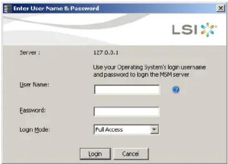
- Select an access mode from the drop-down menu.
- Select Full Access if you need to both view the current configuration and change the configuration.
- Select View Only if you need to only view and monitor the configuration.
- Enter your user name and password, and click Login.

If the computer is networked, this is the login to the computer itself, not the network login.
You must enter the root/administrator user name and password to use Full Access mode. If your user name and password are correct for the Login mode you have chosen, the main MegaRAID Storage Manager window appears.
2.3.6 MegaRAID Storage Manager Window
After you log in, the dashboard view provides an overview of the system and covers the properties of the virtual drives and the physical drives, total capacity, configured capacity, unconfigured capacity, background operations in progress, MegaRAID Storage Manager features and their status (enabled or disabled), and actions you can perform, such as creating a virtual drive and updating the firmware, as shown in the following figure.

You can click the Physical tab to view the drives connected to the controller or Logical tab to view the virtual drives connected to the controller.

The following icons in the left panel represent the controllers, drives, and other devices:

A red circle to the right of an icon indicates that the device has failed. For example, this icon indicates that a drive has failed:
A yellow circle to the right of an icon indicates that a device is running in a degraded state. For example, this icon indicates that a virtual drive is running in a degraded state because a drive has failed:
Properties View Panel
The right panel of the MegaRAID Storage Manager window has the Properties tab that displays information about the selected device. For example, if a controller icon is selected in the left panel, the Properties tab lists information such as the controller name, NVRAM size, and device port count.
Event Log Panel
The lower part of the MegaRAID Storage Manager window displays the system event log entries. New event log entries appear during the session. Each entry has an ID, a timestamp and date, an error level indicating the severity of the event, and a brief description of the event.
Menu Bar
Here are brief descriptions of the main selections on the MegaRAID Storage Manager menu bar.
Manage Menu
The Manage menu has an Exit option for exiting from the MegaRAID
Storage Manager software. It also has a Refresh option for updating the display in the MegaRAID Storage Manager window. (Refresh is seldom required; the display normally updates automatically.)
The Manage menu options also include Check Consistency, Initialize, and Show Progress.
Go To Menu
The Go To menu is available when a controller, physical drive, or virtual disk is selected in the MegaRAID Storage Manager window. The Go To menu options vary depending on what type of device is selected in the left panel of the MegaRAID Storage Manager window. For example, the Scan Foreign
Configuration option is available only when a controller is selected. The options also vary depending on the current state of the selected device. For example, if you select an offline physical drive, the Make Drive Online option will be available in the Go To menu.
Log Menu
The Log menu includes options for saving and clearing the message log.
Tools Menu
On the Tools menu you can select Configure Alerts to access the Event Configuration Notification screen, which you can use to set the alert delivery rules, event severity levels, exceptions, and email settings.
Help Menu
On the Help menu you can select Help > Contents to view the MegaRAID Storage Manager online help file. You can select Help > About MegaRAID Storage Manager to view version information for the MegaRAID Storage Manager software.

- When you use the MegaRAID Storage Manager online help, you may see a warning message that Internet Explorer has restricted the file from showing active content. If this warning appears, click on the active content warning bar and enable the active content.
- If you are using the Linux operating system, you must install Firefox or Mozilla for the MegaRAID Storage Manager online help to display.
Driver Installation
This chapter provides instructions for installing the RAID card driver on different operating systems.
3
3.1 RAID driver installation
After creating the RAID sets for your server system, you are now ready to install an operating system to the independent hard disk drive or bootable array. This part provides instructions on how to install or update the RAID card drivers.

The RAID card driver might be included in the Linux OS installation CD, and could be loaded automatically during OS installation. However, we recommend using the RAID driver packaged in the RAID card support CD for better reliability.
3.1.1 Windows® Server 2012 R2 OS
During Windows® Server 2012 R2 OS installation
To install the RAID card driver when installing Windows® Server 2012 R2 OS:
- Boot the computer using the Windows Windows® Setup process.
® Server 2012 R2 OS installation CD to start the
- Follow onscreen installation.

Ensure to choose Windows 2012 R2 Data center (Server with a GUI) when asked to select the type of operating system you want to install.
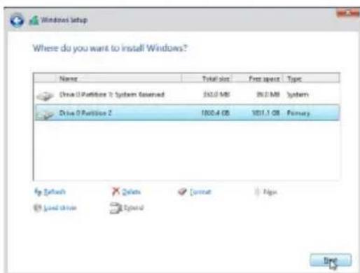
- From the Windows Setup window, click Custom: Install Windows only (Advanced).

- Select and click Load Driver.

-
Remove the installation DVD on the disc drive and replace it with the bundled support DVD that contains the RAID driver.
-
Click Browse and locate the driver on the support DVD.
-
Select the driver from the list then click Next.
-
Wait for the driver installation to finish.
-
When done, remove the support DVD and replace it with the installation DVD
-
Continue installing the operating system and follow onscreen instructions to complete the installation.
-
(optional) Restart the computer.

After Windows® Server 2012 R2 OS installation
To update the RAID card driver after installing Windows® Server 2012 R2 OS:
-
Insert the support DVD that is bundled with your PIKE 3108 Series card into the disc drive.
-
Right-click on the Start button then click Device Manager.
-
Go to Storage Controllers then select LSI Adapter, SAS 3108 Fury-StorPort.
-
Double-click LSI Adapter, SAS3 3108 Fury-StorPort.

The controller name differs according to the installed SAS RAID card.
- Go to the Driver tab then click on Update Driver.
- Click Browse my computer for driver software.
- Click Browse, locate the installer on the support DVD, click OK when done, and then click Next.
- Wait for the driver installation to finish.
- When done, click Close.
- Restart the system.
3.1.2 Red Hat ® Enterprise Linux OS 7.0
To install the RAID card driver when installing Red Hat® Enterprise OS:
- Copy or unzip the dd.iso file to a USB storage device then connect the USB storage device to your system.

To get the dd.iso from the support CD, go to Drivers > PIKE_II_3108-8i_16PD_PIKE_II_3108-8i_240PD_PIKE_II_3108-4i4e_240PD > Driver > Linux > rhel7_oel7_centos7 > disks-1. To download dd.iso from the ASUS website, visit www.asus.com.
- Boot the system from the Red Hat ® OS installation CD.
- From the initial installation page, use the arrow keys to select the installation method then press
to enter the boot option.

- After the boot option, key in:
linux dd
then press

- From the Driver disk device selection list, key in <5>, then press
.
boot: linux dd
[ 8.9954801] sd 0:0:0:0: [sdb] No Caching mode page found
[ 8.995510] sd 0:0:0:0: [sdb] Assuming drive cache: write through
[ 8.9968901] sd 0:0:0:0: [sdb] No Caching mode page found
[ 8.996912] sd 0:0:0:0: [sdb] Assuming drive cache: write through
[ 9.000656] sd 0:0:0:0: [sdb] No Caching mode page found
[ 9.000677] sd 0:0:0:0: [sdb] Assuming drive cache: write through
DD: Checking devices
Page 1 of 1
Driver disk device selection
DEVICE TYPE LABEL UUID
1) sda2 swap 3ad22d43-64ca-40f4-94fb-6bfacdc5a6c0
2) sda3 btrfs 6cbb7e50-2282-4913-b3cf-09782a19042c
3) sda4 xfs 04d8c813-1023-4026-9d31-e40a4d507109
4) sdb1 ufat RHEL-7.0 SE 2DC4-AA51
5) sdc1 ufat PIKE II SER E88A-BE43
<h1 id="to-select-r-refresh-n-next-page-p-previous-page-or-c-continue-5_">to select, 'r'-refresh, 'n'-next page, 'p'-previous page or 'c'-continue: 5_</h1>
- From the Choose driver disk ISO file list, key in <2>, then press
.
boot: Linux dd
[ 8.995480] sd 0:0:0:0: [sdb] No Caching mode page found
[ 8.995510] sd 0:0:0:0: [sdb] Assuming drive cache: write through
[ 8.996890] sd 0:0:0:0: [sdb] No Caching mode page found
[ 8.996912] sd 0:0:0:0: [sdb] Assuming drive cache: write through
[ 9.000656] sd 0:0:0:0: [sdb] No Caching mode page found
[ 9.000677] sd 0:0:0:0: [sdb] Assuming drive cache: write through
DD: Checking devices
Page 1 of 1
Driver disk device selection
DEVICE TYPE LABEL UUID
1) sda2 swap 3ad22d43-64ca-40f4-944b-6bfacdc5a6c0
2) sda3 btrfs 6cbb7e50-2202-4913-b3cf-09782a19042c
3) sda4 xfs 04d8c813-1023-4026-9d31-e48a4d507109
4) sdb1 ufat RHEL-7_0 SE 2EC4-AA51
5) sdc1 ufat PIKE II SER E8BA-EA43
<h1 id="to-select-r-refresh-n-next-page-p-previous-page-or-c-continue-5-222387107-scsi-1200">to select, 'r'-refresh, 'n'-next page, 'p'-previous page or 'c'-continue: 5[ 222.387107] scsi 12:0:0:</h1>
[ 222.4793881 scsi 13:0:0:1: alua: not attached
[ 222.575467] scsi 14:0:0:1: alua: not attached
Page 1 of 1
Choose driver disk ISO file
1) Drivers/PIKE_II_300B-4i4c_PIKE_II_300B-8i/Driver/Linux/mpt3sas-release/citrix6/disks-1/mpt3sas-5.6
2) Drivers/PIKE_II_3108-8i_16PD_PIPE_II_3108-8i_240PD_PIPE_II_3108-4i4e_240PD/Driver/Linux/citrix6/dl
<h1 id="to-select-n-next-page-p-previous-page-or-c-continue-2_">to select, 'n'-next page, 'p'-previous page or 'c'-continue: 2_</h1>
- Key in
, then press to continue.
Page 1 of 1
Choose driver disk ISO file
1) Drivers/PIKE_II_3008-414c_PIKE_II_3008-8i/Driver/Linux/mpt3sas-release/citrix6/disks-1/mpt3sas-5,6
2) Drivers/PIKE_II_3108-81_16PD_PIKE_II_3108-81_240PD_PIKE_II_3108-414e_240PD/Driver/Linux/citrix6/dl
<h1 id="to-select-n-next-page-p-previous-page-or-c-continue-2">to select, 'n'-next page, 'p'-previous page or 'c'-continue: 2</h1>
DD: Checking device /media/DD-search/Drivers/PIKE_II_3108-81_16PD_PIKE_II_3108-81_240PD_PIKE_II_3108-414
.08.00_CitrixXen6.2-1.iso
Page 1 of 1
Driver disk device selection
DEVICE TYPE LABEL UUID
1) sda2 swap 3ad22d43-64ca-40f4-944b-6bfacdc5a6c0
2) sda3 btrfs 6cbb7e50-2202-4913-b3cf-09782a19042c
3) sda4 xfs 04d8c813-1023-4026-9d31-e48a4d507109
4) sdb1 vfat RHEL-7_0 SE ZDC4-AA51
5) sdc1 vfat PIKE II SER E80A-BE43
<h1 id="to-select-r-refresh-n-next-page-p-previous-page-or-c-continue-c">to select, 'r'-refresh, 'n'-next page, 'p'-previous page or 'c'-continue: c</h1>
3.1.3 SUSE Linux OS 12
- Copy or unzip the dd.iso file to a USB storage device then connect the USB storage device to your system.

To get the dd.iso from the support CD, go to Drivers > PIKE_II_3108-8i_16PD_PIKE_II_3108-8i_240PD_PIKE_II_3108-4i4e_240PD > Driver > Linux > sles12 > disks-1. To download dd.iso from the ASUS website, visit www.asus.com.
- Boot the system from the SUSE OS installation CD.
- From the initial installation page, press
and select Yes to load the driver.

- Follow on-screen instructions to continue with the installation.
Loading basic drivers... ok
Starting hardware detection... ok
(If a driver is not working for you, try booting with brokenmodules=driver_name.)

Intel Wellsburg sSATA Controller [AHCI model]
  drivers: ahci*

Intel Wellsburg G-Port SATA Controller [AHCI model]
  drivers: ahci*

Activating usb devices... ok

A USB Flash Drive
  drivers: usb_storage*

JetFlash Transcend 64GB
  drivers: usb_storage*

AMI Virtual Floppy0
  drivers: usb_storage*

AMI Virtual HDisk0
  drivers: usb_storage*

AMI Virtual CDROMO
  drivers: usb_storage*

Intel Ethernet Controller 10-Gigabit X540-AT2
  drivers: ixgbe*

Intel Ethernet Controller 10-Gigabit X540-AT2
  drivers: ixgbe*

Intel I350 Gigabit Network Connection
  drivers: igb*

Intel I350 Gigabit Network Connection
  drivers: igb*
Simplified EU Declaration of Conformity
English ASUSTeK Computer Inc. hereby declares that this device is in compliance with the essential requirements and other relevant provisions of related Directives. Full text of EU declaration of conformity is available at: www.asus.com/support
Address 4F, No. 150, Li-Te Rd., Peitou, Taipei 112, Taiwan
Telephone +886-2-2894-3447
Fax +886-2-2890-7798
Web site https://www.asus.com
Technical Support
Telephone +86-21-38429911
Fax +86-21-58668722 ext: 9101
Online Support https://www.asus.com/support/Product/ContactUs/
Services/questionform/?lang=en
ASUSTeK COMPUTER INC. (Taiwan)
Address 4F, No. 150, Li-Te Rd., Peitou, Taipei 112, Taiwan
Telephone +886-2-2894-3447
Fax +886-2-2890-7798
Web site https://www.asus.com/tw/
Technical Support
Telephone +886-2-2894-3447 (0800-093-456)
Online Support https://www.asus.com/support/Product/ContactUs/
Services/questionform/?lang=zh-tw
ASUSTeK COMPUTER INC. (China)
Address No. 5077, Jindu Road, Minhang District, Shanghai, China
Telephone +86-21-5442-1616
Fax +86-21-5442-0099
Web site https://www.asus.com.cn
Technical Support
Telephone +86-20-2804-7506 (400-620-6655)
Online Support https://www.asus.com/support/Product/ContactUs/
Services/questionform/?lang=zh-cn
ASUS contact information
ASUS COMPUTER INTERNATIONAL (America)
Address 800 Corporate Way, Fremont, CA 94539, USA
Fax +1-510-608-4555
Web site https://www.asus.com/us/
Technical Support
Support fax +1-812-284-0883
General support +1-812-282-2787
Online support https://www.asus.com/support/Product/ContactUs/
Services/questionform/?lang=en-us
ASUS COMPUTER GmbH (Germany and Austria)
Address Harkort Str. 21-23, 40880 Ratingen, Germany
Fax +49-2102-959911
Web site https://www.asus.com/de/
Technical Support
Telephone +49-1805-010923
Support Fax +49-2102-959911
Online support https://www.asus.com/support/Product/ContactUs/
Services/questionform/?lang=de-de
ASUS Czech Service s.r.o. (Europe)
Address Na Rovince 887, 720 00 Ostrava – Hrabová,
Czech Republic
Telephone +420-596766888
Web site https://www.asus.com/cz/
Technical Support
Telephone +420-596-766-891
Fax +420-596-766-329
E-mail advance.rma.eu@asus.com
Online Support https://www.asus.com/support/Product/ContactUs/
Services/questionform/?lang=cs-cz
ASUS contact information
ASUS Holland BV (The Netherlands)
Address Marconistraat 2, 7825GD EMMEN, The Netherlands
Web site https://www.asus.com/nl/
Technical Support
Telephone +31-(0)591-5-70292
Fax +31-(0)591-666853
E-mail advance.rma.eu@asus.com
Online Support https://www.asus.com/support/Product/ContactUs/Services/
questionform/?lang=nl-nl
ASUS Polska Sp. z o.o. (Poland)
Online Support https://www.asus.com/support/Product/ContactUs/Services/
questionform/?lang=pl-pl
ASK-Service (Russia and CIS)
Online Support https://www.asus.com/support/Product/ContactUs/Services/
questionform/?lang=ru-ru
DECLARATION OF CONFORMITY
Per FCC Part 2 Section 2. 1077(a)

Responsible Party Name: Asus Computer International
Address: 800 Corporate Way, Fremont
, CA 94539.
Phone/Fax No: (510)739-3777/(510)608-4555
hereby declares that the product
Product Name : PIKE Card
Model Number : PIKE II 3108-8i/16PD, PIKE II 3108-8i/240PD, PIKE II 3108-4i4e/16PD, PIKE II 3108-4i4e/240PD
Conforms to the following specifications:
☒ FCC Part 15, Subpart B, Unintentional Radiators
Supplementary Information:
This device complies with part 15 of the FCC Rules. Operation is subject to the following two conditions: (1) This device may not cause harmful interference, and (2) this device must accept any interference received, including interference that may cause undesired operation.
Representative Person's Name : Steve Chang / President
Steve Chang
Signature :


- COPYRIGHT © 2017 ASUSTEK COMPUTER INC. ALL RIGHTS RESERVED
- CONTENTS
- CHAPTER 1: PRODUCT INTRODUCTION
- CHAPTER 2: RAID CONFIGURATION
- 2.3 MEGARAID STORAGE MANAGER 2-23
- CHAPTER 3: DRIVER INSTALLATION
- 3.1 RAID DRIVER INSTALLATION 3-2
- SIMPLIFIED EU DECLARATION OF CONFORMITY 3-8
- ASUS CONTACT INFORMATION....3-9
- ABOUT THIS GUIDE
- HOW THIS GUIDE IS ORGANIZED
- WHERE TO FIND MORE INFORMATION
- CONVENTIONS USED IN THIS GUIDE
- TYPOGRAPHY
- PRODUCT INTRODUCTION
- 1.1 WELCOME
- 1.2 PACKAGE CONTENTS
- 1.3 CARD LAYOUT
- 1.3.1 SWITCH SETTINGS
- 1.4 SYSTEM REQUIREMENTS
- 1.5 CARD INSTALLATION
- RAID CONFIGURATION
- 2.1 SETTING UP RAID
- 2.1.1 RAID DEFINITIONS
- 2.1.2 INSTALLING HARD DISK DRIVES
- 2.2 MEGARAID CONFIGURATION UTILITY
- 2.2.1 STARTING THE MEGARAID CONFIGURATION UTILITY
- 2.2.2 MEGARAID CONFIGURATION UTILITY
- MPTFW AND MPTBIOS VERSION OF THE SAS RAID CARD
- UTILITY KEYSTROKES
- 2.2.3 VD MGMT MENU
- 2.2.4 PD MGMT MENU
- 2.2.5 CTRL MGMT MENU
- 2.2.6 PROPERTIES MENU
- 2.2.7 FOREIGN VIEW MENU
- 2.2.8 MANAGING SOFTWARE LICENSING
- 2.2.9 CREATING A STORAGE CONFIGURATION
- 2.2.10 SELECTING ADDITIONAL VIRTUAL DRIVE PROPERTIES
- 2.2.11 MODIFYING CONTROLLER PROPERTIES
- 2.2.12 VIEWING AND CHANGING VIRTUAL DRIVE PROPERTIES
- 2.2.13 DELETING A VIRTUAL DRIVE
- 2.2.14 DELETING A VIRTUAL DRIVE GROUP
- 2.2.15 INITIALIZING A VIRTUAL DRIVE
- 2.2.16 RUNNING A CONSISTENCY CHECK
- 2.3 MEGARAID STORAGE MANAGER
- 2.3.1 HARDWARE AND SOFTWARE REQUIREMENTS
- 2.3.2 INSTALLING MEGARAID STORAGE MANAGER SOFTWARE ON MICROSOFT WINDOWS OS
- 2.3.3 INSTALLING MEGARAID STORAGE MANAGER SOFTWARE FOR LINUX
- 2.3.4 LINUX ERROR MESSAGES
- 2.3.5 STARTING THE MEGARAID STORAGE MANAGER SOFTWARE
- 2.3.6 MEGARAID STORAGE MANAGER WINDOW
- PROPERTIES VIEW PANEL
- EVENT LOG PANEL
- MENU BAR
- MANAGE MENU
- GO TO MENU
- LOG MENU
- TOOLS MENU
- HELP MENU
- DRIVER INSTALLATION
- 3.1 RAID DRIVER INSTALLATION
- 3.1.1 WINDOWS® SERVER 2012 R2 OS
- DURING WINDOWS® SERVER 2012 R2 OS INSTALLATION
- AFTER WINDOWS® SERVER 2012 R2 OS INSTALLATION
- 3.1.2 RED HAT ® ENTERPRISE LINUX OS 7.0
- 3.1.3 SUSE LINUX OS 12
- SIMPLIFIED EU DECLARATION OF CONFORMITY
- TECHNICAL SUPPORT
- ASUSTEK COMPUTER INC. (TAIWAN)
- ASUSTEK COMPUTER INC. (CHINA)
- ASUS CONTACT INFORMATION
- ASUS COMPUTER INTERNATIONAL (AMERICA)
- ASUS COMPUTER GMBH (GERMANY AND AUSTRIA)
- ASUS CZECH SERVICE S.R.O. (EUROPE)
- ASUS HOLLAND BV (THE NETHERLANDS)
- ASUS POLSKA SP. Z O.O. (POLAND)
- ASK-SERVICE (RUSSIA AND CIS)
- DECLARATION OF CONFORMITY
- SUPPLEMENTARY INFORMATION
Brand : ASUS
Model : PIKE II 3108-8i-16PD/2G
Category : Controller