USER MANUAL DP50747 SANYO
Visit our Web site at
www.sanyoctv.com
or call toll free
1-800-877-5032
We can Help!
Printed in U.S.A. SMC, March 2007
WARNING: TO REDUCE THE RISK OF FIRE OR ELECTRIC SHOCK, DO NOT EXPOSE THIS APPLIANCE TO RAIN OR MOISTURE.
IMPORTANT SAFETY INSTRUCTIONS
-
Read these instructions.
-
Keep these instructions.
-
Heed all warnings.
-
Follow all instructions.
-
Do not use this apparatus near water.
-
Clean only with dry cloth.
-
Do not block any ventilation openings. Install in accordance with the manufacturer's instructions.
-
Do not install near any heat sources such as radiators, heat registers, stoves, or other apparatus (including amplifiers) that produce heat.
-
Do not defeat the safety purpose of the polarized or grounding-type plug. A polarized plug has two blades with one wider than the other. A grounding-type plug has two blades and a third grounding prong. The wide blade or the third prong are provided for your safety. If the provided plug does not fit fully into your outlet, consult an electrician for replacement of the obsolete outlet.
-
Protect the power cord from being walked on or pinched particularly at plugs, convenience receptacles, and the point where they exit from the apparatus.
-
Only use attachments/accessories specified by the manufacturer.
-
Use only with the cart, stand, tripod, bracket, or table specified by the manufacturer, or sold with the apparatus. When a cart is used, use caution when moving the cart/apparatus combination to avoid injury from tip-over.

-
Unplug this apparatus during lightning storms or when unused for long periods of time.
-
Refer all servicing to qualified service personnel. Servicing is required when the apparatus has been damaged in any way, such as power-supply cord or plug is damaged, liquid has been spilled or objects have fallen into the apparatus, the apparatus has been exposed to rain or moisture, does not operate normally, or has been dropped.
-
If an outside antenna is connected to the television equipment, be sure the antenna system is grounded so as to provide some protection against voltage surges and built up static charges. In the U.S. Selection 810-21 of the National Electrical Code provides information with respect to proper grounding of the mast and supporting structure, grounding of the lead-in wire to an antenna discharge unit, size of grounding conductors, location of antenna discharge unit, connection to grounding electrodes, and requirements for the grounding electrodes.
-
An outside antenna system should not be located in the vicinity of overhead power lines or other electrical light or power circuits, or where it can fall into such power lines or circuits. When installing an outside antenna system, extreme care should be taken to keep from touching such power lines or circuits as contact with them might be fatal.
EXAMPLE OF ANTENNA GROUNDING ACCORDING TO NATIONAL ELECTRICAL CODE, ANSI/NFPA 70
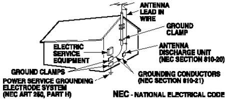
Note to CATV system installer: This reminder is provided to call the CATV system installer's attention to Article 820-40 of the NEC that provides guidelines for proper grounding and, in particular, specifies that the cable ground shall be connected to the grounding system of the building, as close to the point of cable entry as practical.
- Wall or Ceiling Mounting—The product should be mounted to a wall or ceiling only as recommended by the manufacturer.
- "Apparatus shall not be exposed to dripping or splashing and no objects filled with liquids, such as vases, shall be placed on the apparatus."
- Where the Mains plug is used as the disconnect device, the disconnect device shall remain readily operable.
- A warning that an apparatus with Class1 construction shall be connected to a Mains socket outlet with a protective earthing connection.
Welcome to the World of Sanyo
Thank you for purchasing this Sanyo Plasma High-Definition Digital Television. You made an excellent choice for Performance, Reliability, Features, Value, and Styling. If assistance is needed, please call 1.800.877.5032 or visit our website at www.sanyoctv.com. We can help!
CONTENTS
IMPORTANT SAFETY INSTRUCTIONS 2
SPECIFICATIONS 3
HANDLING PRECAUTIONS 4
REMOVING THE PLASMA STAND (OPTIONAL) 4
WALL MOUNTING (OPTIONAL) 4
POSITIONING PRECAUTIONS 4
PROTECTING THE PLASMA SCREEN 4
GETTING STARTED (REQUIRED INITIAL SETUP) ..... 5
Installing Batteries in the Remote Control 5
Connect Signal (Digital / Analog) 5
Connect AC Power Cord 5
Perform All Channel Search 5
HDTV SIDE AND BACK PANELS 6
DIGITAL AV CONNECTIONS
HDMI Input 1/2/3 Connection 7
HD DVD Player / Game System 7
Set-top Box (STB) with DVI Output 7
VIDEO2/3 COMPONENT JACKS CONNECTION
DVD Player 8
DIGITAL AUDIO OUT CONNECTION
Multichannel Receiver 8
ANALOG AUDIO OUT CONNECTION
Stereo Amplifier 9
FREQUENT ASKED QUESTION (FAQ)
The picture is not as clear as it should be. Am I using the best quality connection?
Picture quality is classified as follows:
RF Cable connection (analog) Basic
Video1 (Composite-Yellow) Good
Video1 (S-Video) Better
Video2/3 (Component: green, blue, red) ... Exceptional
HDMI1 / 2 / 3 or Antenna In .........Ultimate
CAUTION: FCC Regulations state that improper modifications or unauthorized changes to this unit may void the user's authority to operate the unit.
VIDEO1 ANALOG AV CONNECTIONS 9
VCR (or other analog device) 9
Connect Analog Cable Box or Cable, VCR, and an Antenna 10
How to Operate the On-Screen Menu 12
Menu Navigation Map 12
Menu Options:
All Channel Search 12
Analog Antenna Signal (Optional) 12
Picture/Sound Adjustment 12
Menu Language 12
Digital Cable Search (Optional) 13
Digital Add-On Search 13
Channel Scan Memory 13
Digital Caption 14
V-Guide (Parental Control) 14
Energy (Power) Saver 15
Picture Rotation (Screen Saver) 15
White Pattern (Panel Repair) 15
HELPFUL HINTS (PROBLEMS/SOLUTIONS) 16
WARRANTY 17
SPECIFICATIONS
POWER REQUIREMENT: Source: AC 120V, 60Hz
AC POWER CONSUMPTION: 460 Watts (Maximum)
Manufactured under license from Dolby Laboratories. "Dolby" is a trademark of Dolby Laboratories.
VIZON® with a double “Z” is a registered trademark of Sanyo Manufacturing Corporation.

"As an ENERGY STAR® Partner, Sanyo Manufacturing Corporation has determined that this product meets the ENERGY STAR® guidelines for energy efficiency."

HANDLING PRECAUTIONS
- Handle the Plasma DTV carefully when installing. Do Not Drop.
- Throughout the installation process, handling by more than two people is recommended.
- When removing the stand, use a working space that is larger than the screen size. The work surface must be flat and covered with a soft cloth or blanket to protect the screen surface.
- Before placing the Plasma DTV face down, make sure there are no objects under the screen. Leaving any object may cause damage on the screen surface.
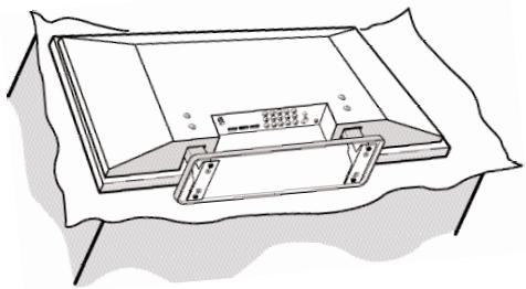
REMOVING THE STAND (Optional)
Tools Needed: Phillips screwdriver
Important Note: Place DTV face down on a padded or cushioned surface that is larger than the screen size to protect the screen and finish. Handling by more than two people is recommended.
1 Remove four (4) screws from the metal bracket. CAUTION: Hold the stand firmly as you remove the last screw.
2 Carefully remove the stand.
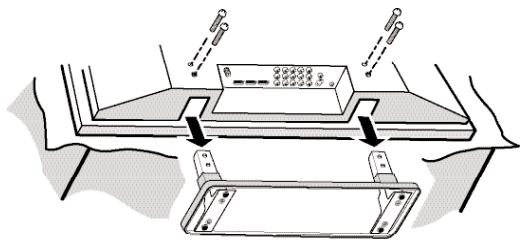
WALL MOUNTING (Optional)
Use the threaded inserts on the back of your Plasma DTV to secure it using a wall mounting kit.
(UNIVERSAL standard interface 480 × 200 and 480 × 360 .)
Note: Wall Mounting kit is not supplied.
Mounting screws measurements: M6 Diameter, Length—12mm (maximum).

POSITIONING PRECAUTIONS
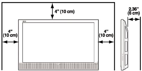
- Place this Plasma DTV as indicated here. Failure to do so may result in a fire hazard. Allowing the proper amount of space at the top, sides, and rear of the Plasma DTV cabinet is critical for proper air circulation and cooling of the unit. The dimensions shown here indicate the minimum space required. If the Plasma DTV is to be built into a compartment or similarly enclosed, these minimum distances must be maintained.
- Do not cover the ventilation slots on the Plasma DTV. Heat build-up can reduce the life of your Plasma DTV, and can also be dangerous.
- If the Plasma DTV is not to be used for an extended period of time, unplug it from the power outlet.
PROTECTING THE PLASMA SCREEN
The screen is likely to be damaged if it is not maintained properly. Do not use hard objects such as hard cloth or paper. Do not use excessive pressure when
cleaning the screen; excessive pressure can cause permanent discoloration or dark spots.
NEVER spray liquids on the screen.

1 Install batteries in remote control (2AAA, not included).

PRECAUTIONS
To ensure safe operation, please observe the following precautions:
Replace both batteries at the same time. Do not use a new battery with a used battery.
Risk of explosion, if battery is replaced by an incorrect type.
Do not expose the Remote Control Unit to moisture or heat.
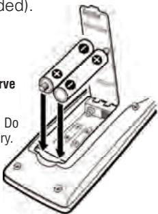
Match the "+" and "-" signs on the batteries with marks inside the remote control.
3 Connect AC Power Cord (supplied) to the Plasma DTV and electrical outlet as shown here.
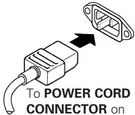
To POWER CORD CONNECTOR on
back of Plasma DTV.
The AC outlet must be near this equipment and must be easily accessible.
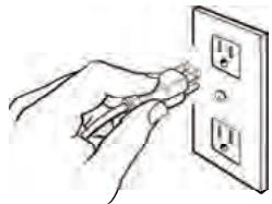
To 120 V AC outlet.
2 Connect Signal to the DTV's Integrated Analog / Digital 75 ohm Antenna Input terminal.
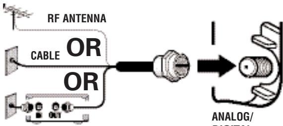
CABLE BOX OR SATELLITE BOX
ANALOG/ DIGITAL ANTENNA IN
THE TUNER IN THIS PLASMA DTV CAN RECEIVE:
- Digital and / or Analog Off-Air Signals from an RF antenna.
OR
- Analog or ClearQAM cable channels.
Note: You must search for ClearQAM channels using the "Digital Cable Search" menu option. OR
3. The output from a VCR or cable box.
Digital signals can also be received through the HDMI jacks.
Signals from a Set-top (STB) Box should be received through the Video 1, 2, or 3, or HDMI Input 1, 2, or 3 jacks.
This DTV can receive ANY unscrambled RF signal being broadcast.
4 Press the POWER key. (Follow on-screen instructions).
5 Perform "All Channel Search." The All Channel Search will search for off-air digital and analog channels, and analog cable channels. The DTV can receive cable or off-air channels, but not at the same time. If after two searches the DTV
INITIAL ON-SCREEN ALL CHANNEL SEARCH
First
Please connect all signals and antennas to
Jacks and terminals on the back of the TV. Then press the Channel UP key.. Press EXIT key to cancel setup
still fails to detect any channels, the DTV will tune to Video1.
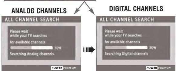
Note: If EXIT is pressed, the DTV will skip Channel Search and tune to Video1 without storing any channels in the Channel Map database.

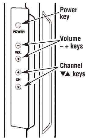
SIDE PANEL (see item 8 on page 11)
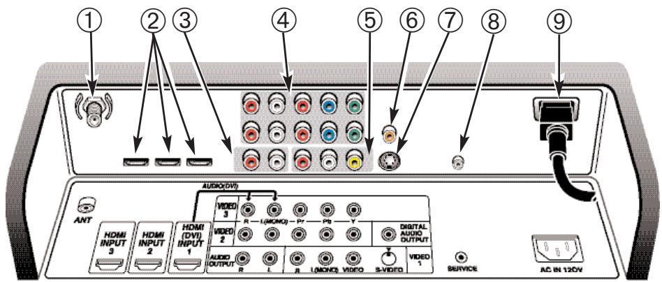
BACK PANEL
① Analog / Digital Antenna Input, PAGE 5—Connect an RF antenna or Analog Cable system to this jack.
② HDMI INPUT 1/2/3 (High-Definition Multimedia Interface), PAGE 7—Connect digital video equipment to these jacks, such as, a DVD player or HD satellite receiver. It takes only one high-bandwidth cable (not supplied) to communicate between audio/video equipment and this DTV. HDMI (DVI) INPUT 1 jack is compatible with DVI equipped AV devices. (Separate audio connection and an adapter are required for DVI device.)
③ Analog Audio Out (L/R) Jacks, PAGE 9—Connect external audio equipment here.
④ Component Video Input (VIDEO 2 or VIDEO 3), PAGE 8—Connect digital video equipment to the Y (Green), Pb (Blue), Pr (Red) and Audio L/R jacks. These jacks will automatically detect the type of signal being received.
⑤ Audio/Video Input (VIDEO 1), PAGES 9 ~ 10—Connect analog video equipment here.
Note: S-Video connection overrides the (Video 1) composite video connection.
⑥ Digital Audio Output, PAGE 8—Use a Phono-Type Digital Audio Out Cable to connect Digital Audio Output to an advanced stereo home theater system equipped with Dolby® Digital 5.1.
⑦ S-Video Input (VIDEO 1), PAGE 9—To enhance video detail use the S-Video jack instead of the Video jack, if available on your external equipment. (S-Video connection will override connection to the Video input jack [VIDEO 1]).
⑧ Service Jacks—For production use only.
⑨ AC IN 120V—Connect power cord here. See page 5.
DIGITAL AV CONNECTIONS—Receiving the Ultimate Picture
1 Connect the external equipment's HDMI Output to a DTV HDMI Input.
2 Press INPUT to select HDMI 2 or HDMI 3 to view the digital program.
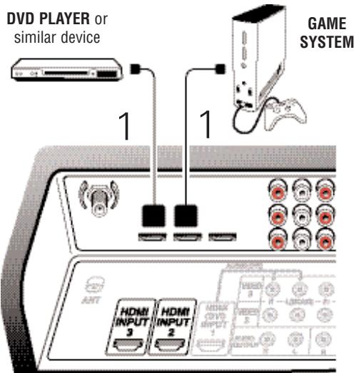
DVD PLAYER AND GAME SYSTEM CONNECTED TO HDMI INPUT 2, & INPUT 3
BACK VIEW OF DTV
(HDMI INPUT 2 / HDMI INPUT 3)
HDMI CABLE
[Gently insert this cable into HDMI jack for Audio and Video.]
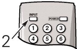
REMOTE CONTROL
1 Connect the Set-top Box (STB) DVI Output to the DTV's HDMI INPUT 1.
Note: Check with your local electronics store for a DVI to HDMI Adapter Cable that matches your equipment and the DTV.
2 Connect the STB Audio out to the DTV's VIDEO3 Audio In L/R.
3 Press INPUT to select HDMI 1 to view the digital program.
IMPORTANT FACT: Only the HDMI (DVI) INPUT 1 jack can accept a DVI (digital video interface) connection.
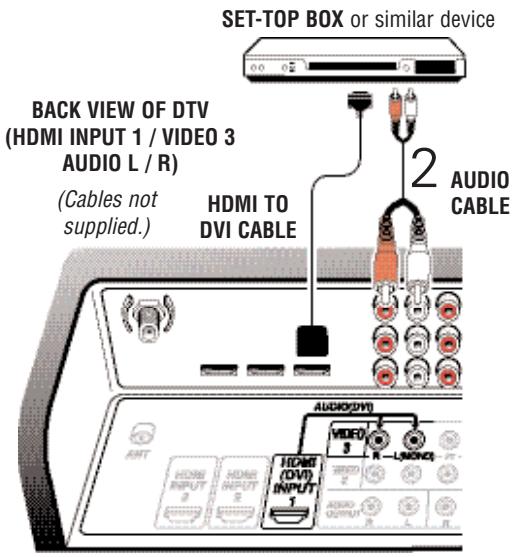
DVI STB CONNECTED TO HDMI INPUT 1 (Can be an HD Satellite Receiver or similar device)
OPERATING TIPS:
Press the INPUT key after connecting cables to access the AV Inputs. There is NO need to tune to a blank channel.
HDMI INPUT 2, and HDMI INPUT 3 jacks have identical functions with HDMI INPUT 1 having an additional feature for DVI connection. Compatible video devices can be connected to either set of jacks.
Use HDMI (DVI) INPUT 1 to connect your DVI device, make sure you connect Audio out to the DTV's VIDEO 3 Audio In.
The VIDEO 3 audio jacks are used to receive the audio from the DVI device. These video jacks cannot be used when a DVI device is connected.
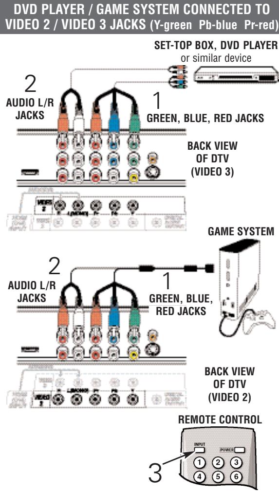
VIDEO 2 & 3 COMPONENT: GREEN, BLUE, RED—An Exceptional Picture
CONNECTING A STB, DVD, OR GAME
1 Connect a Component Cable to the VIDEO 2/3 Green, Blue, and Red video jacks.
2 Connect an Audio Cable to the VIDEO 2 / 3 White and Red audio jacks.
3 Press INPUT to select Video 2 or Video 3 to view the program.
Note:VIDEO 2 andVIDEO 3 jacks have identical functions. Compatible video devices can be connected to either or both jacks.
DIGITAL AUDIO JACK
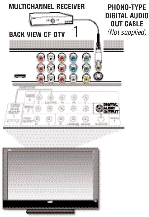
CONNECTING A MULTICHANNEL RECEIVER TO THE DTV
1 Connect a Multichannel Receiver to the DTV Digital Audio Output as shown.
Note: Dolby® Digital 5.1 audio is available at the Digital Audio Output only when received as part of a Digital Antenna signal being viewed on the screen.
MULTICHANNEL RECEIVER CONNECTED TO DIGITAL AUDIO OUT JACK
IMPORTANT FACT: To view available High-Definition (HD) programs, you must connect your HD equipment to the Component or HDMI jacks.
OPERATING TIPS:
Press the INPUT key after connecting cables to access the AV Inputs. There is NO need to tune to a blank channel.
- You DO NOT need to tune the DTV to Channel 3 or 4 to view a DVD program.
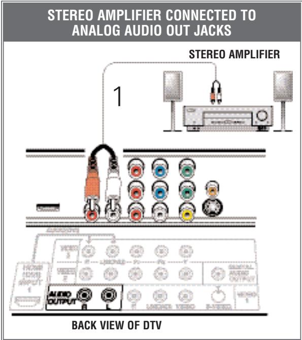
CONNECTING A STEREOM AMPLIFIER TO THE DTV
AUDIO OUT (FIXED ANALOG) JACKS
1 Connect a Stereo Amplifier to the DTV Audio Out jacks as shown.
Note: Do not connect external speakers directly to the DTV.
OPERATING TIPS:
Position your DTV at least 2 feet from stereo speakers. The magnets in the speakers may affect the picture quality.
For Mono VCR (Single Audio Jack), connect VCR Audio Out to DTV Audio (L) Input.
- "No Signal" will appear randomly on the screen when no signal is detected at the VIDEO1 video jack.
VIDEO 1 (COMPOSITE-YELLOW)—A Good Picture or (S-VIDEO)—A Better Picture
CONNECTING A VCR OR DVD TO THE DTV
1 Connect a Composite Cable to the VIDEO1 Yellow, White, and Red AV jacks as shown.
OPTIONAL
Connect DVD to the DTV S-Video In Jack, if available on your external equipment.
Note: S-Video jack connection overrides a Video jack connection (VIDEO 1).
3 Press INPUT to select Video 1 to view the DVD or VCR program.
IMPORTANT FACTS:
Don't be confused by the phrase "Available in High-Definition." Composite jacks offer only 480i (SDTV) resolution.
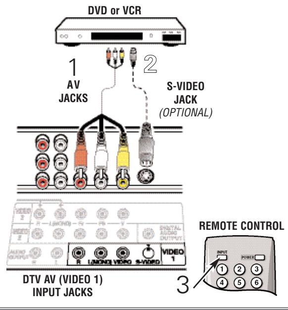
DVD OR VCR CONNECTED TO VIDEO1 JACKS
VIDEO 1 (Continued on page 10)
TO CONNECTANALOGCABLEBOXOR CABLE,VCR,AND ANANTENNA
With Cable Box
1 Connect Analog Cable Box "Antenna Out" to the VCR "Antenna In."
2 Connect the VCR AV out jacks to VIDEO 1 Yellow, White, and Red jacks.
3 Connect an Antenna to the DTV Analog/Digital Antenna In terminal.
4 Tune VCR to channel 3 or 4 to match your Cable Box.
5 Press INPUT to select Video 1 to watch Analog Cable channels OR to TV channels to watch Antenna channels.
6 Select Cable channels with the cable box remote control. Select Antenna channels with the DTV remote control.
Without Cable Box
1 Connect Analog Cable system to the VCR "Antenna In."
2 Connect the VCR AV out jacks to VIDEO 1 Yellow, White, and Red jacks.
3 Connect an Antenna to the DTV Analog/Digital Antenna In terminal.
4 Press INPUT to select Video 1 to watch Analog Cable channels OR to TV channels to watch Antenna channels.
5 Select Analog Cable channels with the VCR's remote control. Select Antenna channels with the DTV remote control.
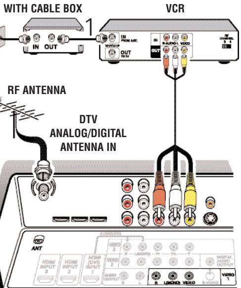
CONNECT ANALOG CABLE BOX, VCR, & ANTENNA
DTV AV (VIDEO 1) INPUT JACKS
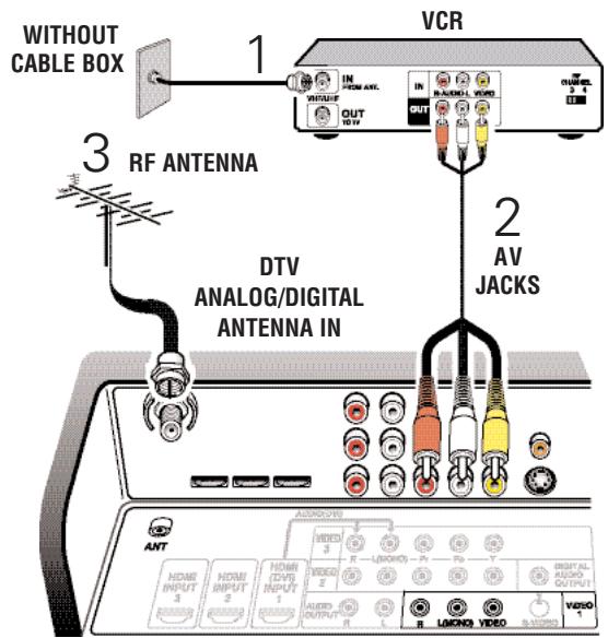
CONNECT ANALOG CABLE SYSTEM, VCR, & ANTENNA
DTV AV (VIDEO 1) INPUT JACKS
Note: Numerical direct channel selection works for either Analog or Digital channels in memory but not both at the same time.
(3) Info Key—Press to display the Digital and Analog Full Banner information which includes: Channel Number (Major and Minor), Tuner ID, Station ID, V-Chip Program Rating, Program Title, Audio Info, and Signal Strength, if available. (Press again to remove the display.)
④ Recall Key—Press to switch between the last two channels. The Recall key cannot toggle between a Digital channel and an Analog channel.
⑤ 1- - Key—For Analog Cable channels above 100, press this key, then press the other two numbers.
⑥Menu Navigational Keys:
Menu—Press to display the on-screen menu. Cursor (up) (down) keys—Use these keys to move the cursor up and down within the menu. Cursor < ( left (right) keys—Use these keys to move the cursor left and right within the menu. Enter Key—Press to select an option from the menu system, when required.
Exit Key—Press to exit from the menu system.
⑦ Caption Key—Press to select mode options: Digital CC1 Digital CC6, or Analog CC1 CC4, OFF, or QuikCap.
⑧ Channel Scanning (CH ▲▼) Keys—Press to scan through the channels in memory.
Volume Keys—Press VOL - + to adjust.
9Pix Shape Key—Use this key to change the video display format. Available options depend on signal received and the broadcast's aspect ratio. They may include: PIX1, PIX2, PIX3, and PIX4.
10 Audio Key—Press to select the desired audio mode (if available).
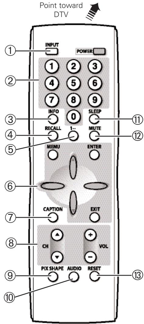
① Sleep Key—Press this key then the "0" key to set the Sleep Off Timer. Time can be set in 30-minute increments up to 3 hours.
Note: The Sleep Timer cancels when the TV is turned off or if a power failure occurs.
12 Mute Key—Press once to mute the sound.
⑬ Reset Key—Press this key twice to restore factory settings. The TV will automatically start Channel Search and clear all customized settings.
Note: Channel scan memory database of digital and analog channels will be replaced. If desired, personal settings can be made again using the menu options.
Some Menu options are specific to Digital and Analog signals. To access these options, you must first tune the DTV to a digital or analog channel.
Not available" will be displayed on the screen if an unavailable menu option is selected.
Press the MENU key to display the Main menu.
Use the CURSOR keys to highlight menu item.
3 Use the CURSOR < > keys to select or adjust menu item.
4 Press ENTER to activate setting, if needed.
When you have finished making adjustments, press the EXIT key to return to normal TV viewing.
Note: For menu items that have sub menus, follow on-screen instructions to select and make adjustments.
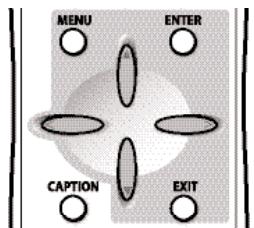
REMOTE CONTROL-CURSOR KEYS
TIP:
Along with the on-screen instructions, several features will be explained in more detail, see pages 13 ~ 15.
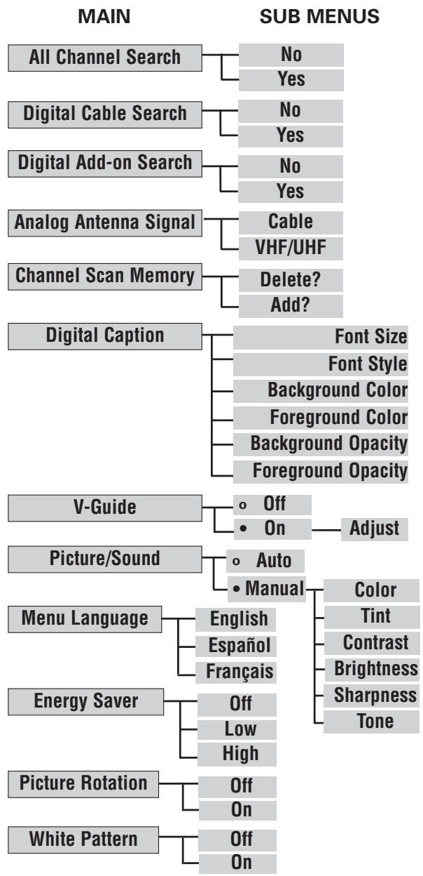
MENUNAVIGATIONALMAP
DIGITAL CABLE SEARCH (OPTIONAL)
This DTV can receive unscrambled (ClearQAM) digital cable channels, when available. However, not all cable companies provide ClearQAM digital channels.
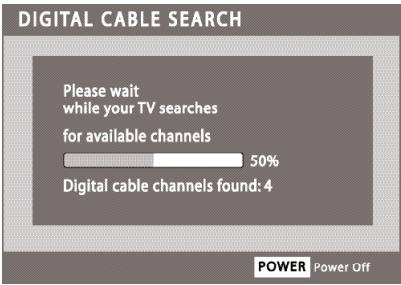
Digital Cable Search process will take about 10 minutes, please be patient.
IMPORTANT FACTS: This DTV maintains only one database of digital channels. Therefore, when you search for ClearQAM digital cable channels, the database of antenna digital channels will be deleted. You will be able to receive only those ClearQAM channels your cable company provides.
To restore the antenna digital channel database, reconnect the antenna and use the menu system to perform an All Channel Search.
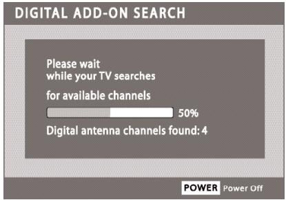
DIGITAL ADD-ON SEARCH
To add new digital channels to the existing antenna channel database, use Digital Add-on Search. Also, use this feature to add channels when broadcast towers are in multiple directions from your location.
For more info go to www.antennaweb.org and type in your zip code to obtain specific tower and antenna information. Then adjust your antenna and repeat the Digital Add-on Search.
CHANNEL SCAN MEMORY
This is a list of active channels that you can scan through using the Channel Scan CH (up) CH (down) keys. The list can be customized by deleting and/or adding channels as shown.
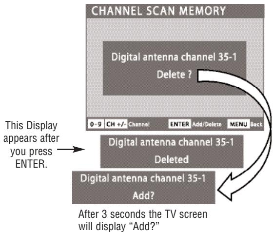
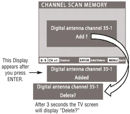
IMPORTANT FACTS: When a digital channel is deleted, all of that channel's sub-channels are deleted as well.
Only previously deleted digital channels can be added back to the Channel Scan Memory.
If one digital sub-channel is added back to the Channel Scan Memory list, all of that channel's sub-channels will be added back.
DIGITAL CAPTION
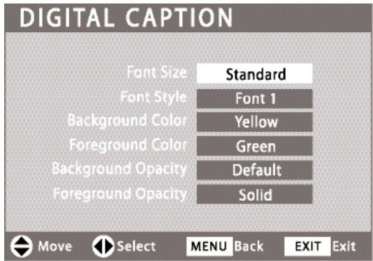
Closed-Captioning is text information transmitted along with the picture and sound. Turning Captioning ON causes the DTV to open these captions (digital or analog) and superimpose them on the screen. (Local broadcasters decide which caption signals to transmit.)
Digital Captions can be changed using the menu settings as shown.
OPERATING TIPS:
If Background Opacity is set to transparent, captions may be difficult to see.
Only true EIA 708B Digital Closed-Captions are affected by all of these settings.
V-GUIDE (PARENTAL CONTROL)
NOTE: THIS FEATURE IS DESIGNED TO COMPLY WITH THE UNITED STATES OF AMERICA'S FCC V-CHIP REGULATIONS. THEREFORE, IT MAY NOT FUNCTION WITH BROADCASTS THAT ORIGINATE IN OTHER COUNTRIES.
Use this feature to automatically block programs with content you deem as inappropriate for children to view.
This Sanyo television is equipped with an electronic V-Chip to interpret MPAA (Motion Picture Association of America) and TV Parental Guidelines rating codes. When these codes are detected, the DTV will automatically display or block the program, depending upon choices you make when setting up the V-Guide system.
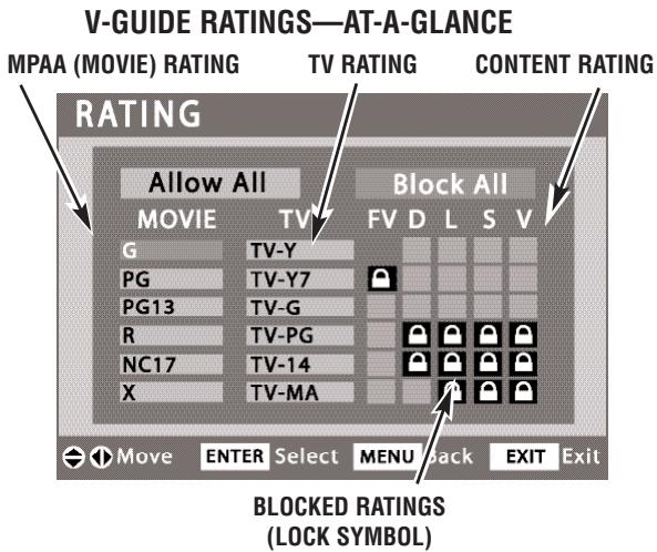
Content ratings are represented by the initials: FV (fantasy violence), L (adult language), S (sexual situations), V (violence), and D (suggestive dialog).
OPERATING TIPS:
You can block portions of a DTV rating by choosing one or more of the Content ratings (D, L, S, and V). By blocking just the L and S content ratings of TV-14, for example, TV-14 rated programs with a D and/or V content rating could still be viewed.
V-Guide limits on programming received via the Analog antenna input, Digital antenna input, Video 1 input, and any 480i signals received through the Component jacks can be controlled by this DTV.
V-Guide Limits on digital programming received through the component jacks and HDMI jacks are controlled by the external equipment connected to these jacks. Refer to your external device's owner's manual for instructions on setting V-Guide Limits.
ENERGY (POWER) SAVER
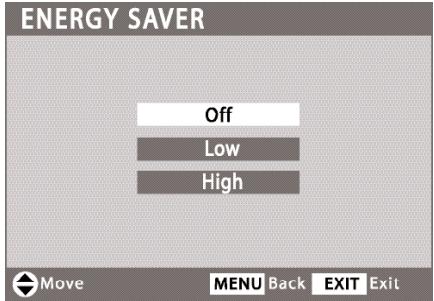
This power saving feature reduces the brightness level. The power saving function options:
- OFF - the feature is off and the power consumption is normal.
- LOW - power saving level is low and the brightness level is lower than normal.
- HIGH - power saving level is high and the brightness is set to the lowest level.
OPERATING TIP:
The Energy saver settings level will vary depending on the Picture/Sound mode. For instance, the energy low level settings may be different between the manual picture/sound mode (customized settings) than the auto mode (factory settings).
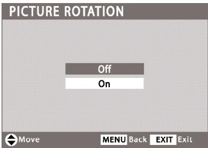
PICTURE ROTATION (SCREEN Saver)
Displaying a still picture for a long time may cause an "afterimage" or "ghost" on the screen. To neutralize this situation, use the Picture Rotation function.
Note: When the Picture Rotation is set to ON, the DTV automatically changes the display position every 15 minutes to avoid afterimage.
WHITE PATTERN (PANEL REPAIR)

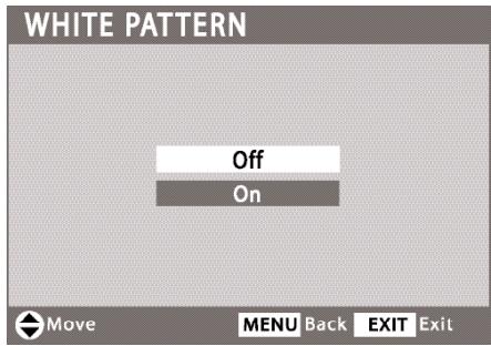
Use this feature to repair the Plasma screen.
If an afterimage occurs, use the White Pattern feature immediately to repair the panel. The more severe the afterimage, the longer the curing process may take. It may be impossible to repair all cases of afterimage burn.
The sooner you remove a still picture and activate White Pattern, the more likely it is that the panel can be repaired.
Notes: Afterimage (or image burn) is not covered under warranty.
When the White Pattern is activated the screen will instantly turn completely white. The On time is automatically set for 30 minutes.
Pressing any key except Volume Mute, and Audio will cancel the curing process and return the DTV to normal viewing.
HELPFUL HINTS (PROBLEMS/SOLUTIONS)
Please check the chart below and try the solutions listed for your problem. If the problem still persists, before returning your HDTV, please
call us toll free at 1.800.877.5032 or visit our website at www.sanyoctv.com. We can Help!
| Problem: | Check these Conditions: | Try these Solutions: | Page No. |
| No picture, sound (Digital Picture) | ·Check antenna/external connections
·May be station trouble, NO signal broadcast.
·MUTE function may be on.
·The Plasma DTV takes a few seconds to display an image. | ·Adjust antenna.
·Try a different channel.
·Press RESET key to restart channel search (All customized settings will be cancelled.)
·Adjust Volume. | 5
7 ~ 10 |
| No Captioning | ·Check if station is broadcasting a Closed-Caption signal.
·Select another channel. | ·Press CAPTION key to select captioning mode. | 14 |
| Cannot customize Caption | ·Digital Caption signal is not being broadcast. | ·Press CAPTION key to select Analog captioning. | 14 |
| Cannot display picture on a full screen | ·Check Aspect Ratio of broadcast. | ·Press PIX SHAPE key to change setting. | 11 |
| Poor Picture/Sound (watching Analog) | ·Check if program is in color.
·Check antenna/external connections.
·Color or Tint misadjusted.
·May be station trouble.
·Maybe MUTE function is on. | ·Try a different channel.
·Adjust antenna.
·Press RESET key to restart channel search.
·Adjust Volume. | 11 |
| “No Signal” message appears on screen | ·Check Audio/Video connections.
·Check external equipment connections.
·Check external equipment setting.
·Check antenna connection. | ·Press INPUT key.
·Switch on external equipment.
·Turn antenna, install signal booster.
·Set external equipment output connections to match input connections. | 7 ~ 10 |
| Pixilation of Digital image | ·Press INFO key and check signal strength. | ·Turn antenna, install signal booster.
·Install outdoor Digital antenna. | 5, 11 |
| Cannot select or scan some channels | ·Channel may be removed from memory.
·Check antenna connections.
·No digital signal being broadcast.
·V-Guide is set to block programming.
·Weak Signal. | ·Select CH. Scan Memory and manually add channels or start channel search.
·Set V-Guide to “None” or press RESET key to clear all settings and restart channel search.
·Turn antenna, install signal booster. | 13
14
11 |
| No Cable channels above number 13 | ·Cable Channel Indicator C should appear next to channel number. | ·Switch Analog Antenna Signal Selection to Cable. | 12 |
| Remote Control will not work TV | ·Check batteries.
·Check if TV is plugged in. | ·Replace batteries.
·Aim remote control at front of TV. | 5, 11 |
| Afterimages (ghosts) appear | ·Do not display the same image on screen for a long period of time. Afterimages or ghosts may appear on parts of the panel. | ·Use the Picture Rotation Screen Saver function.
·Use the White Screen Feature to repair the panel. | 15 |
ONE-YEAR LIMITED PARTS AND LABOR WARRANTY
THIS LIMITED PARTS AND LABOR WARRANTY IS VALID ONLY ON SANYO TELEVISIONS PURCHASED AND USED IN THE UNITED STATES OF AMERICA, CANADA, AND PUERTO RICO, EXCLUDING ALL OTHER U.S. TERRITORIES AND PROTECTORATES. THIS LIMITED WARRANTY APPLIES ONLY TO THE ORIGINAL RETAIL PURCHASER, AND DOES NOT APPLY TO PRODUCTS USED FOR INDUSTRIAL OR COMMERCIAL PURPOSES.
WARRANTY APPLICATION
FOR ONE YEAR from the date of original retail purchase Sanyo Manufacturing Corporation (SMC) warrants this TV to be free from manufacturing defects in materials and workmanship under normal use and conditions for parts and labor.
For the FIRST 90 DAYS from the date of original retail purchase, Sanyo Manufacturing Corporation will replace any defective TV via exchange at the retailer. To ensure proper warranty application, keep the original-dated-sales receipt for evidence of purchase. Return the defective TV to the retailer along with the receipt and the included accessories, such as the remote control. The defective TV will be exchanged for the same model, or a replacement model of equal value, if necessary. Replacement model will be contingent on availability and at the sole discretion of Sanyo Manufacturing Corporation.
THE FOREGOING WARRANTY IS EXCLUSIVE AND IN LIEU OF ALL OTHER WARRANTYES OF MERCHANTABILITY OR FITNESS FOR A PARTICULAR PURPOSE.
OBLIGATIONS
For one year from the date of purchase, Sanyo Manufacturing Corporation warrants this product to be free from defects in material and workmanship under normal use and conditions. During the first 90 days under this warranty for any manufacturing defect or malfunction Sanyo Manufacturing Corporation will provide a new TV via exchange at the retailer.
HOW TO MAKE A CLAIM UNDER THIS WARRANTY
Please call 1-800-877-5032. Please be prepared to give us the television's model number and serial number when you call. The model number and serial number are printed on a label attached to the back of the unit.
For customer assistance, call toll free 1-800-877-5032.
Weekdays 7:30 AM - 7:00 PM Central Time
Saturday 7:30 AM - 4:00 PM Central Time
This warranty expresses specific contractual rights; retail purchasers may have additional statutory rights which vary from state to state.
(EFFECTIVE: March 1, 2007)
For your protection in the event of theft or loss of this product, please fill in the information requested below and KEEP IN A SAFE PLACE FOR YOUR OWN PERSONAL RECORDS.
Model No.
Date of Purchase
Serial No.
Purchase Price
(Located on back of unit)
Where Purchased

Sanyo Manufacturing Corp.
3333 Sanyo Road, Forrest City, AR 72335

US
This symbol on the nameplate means the product is Listed by Underwriters' Laboratories Inc. It is designed and manufactured to meet rigid U.L. safety standards against risk of fire, casualty and electrical hazards.
ESPÁNOL MANUAL DE INSTRUCCIONES
Guía-V (Control Paternal) 32
First Please connect all signals and antennas to Jacks and terminals on the back of the TV.
Then press the Channel UP key. Press EXIT key to cancel setup
Sanyo Manufacturing Corp.
3333 Sanyo Road, Forrest City, AR 72335

ENLÉVEMENT DU SOCLE INCLINABLE 38
MONTAGE MURAL (FACULTATIF) 38
PRECAUTIONS LORS DE LA MISE EN PLACE 38
FOIRE AUX QUESTIONS?
Consummation: 460 Watts (Maximum)
ENLÉVEMENT DU SOCLE INCLINABLE
APPLICATION DE LA GARANTIE
Sanyo Manufacturing Corp.
3333 Sanyo Road, Forrest City, AR 72335