
XeRun 3660 SD G2 - Remote control toy Hobbywing - Free user manual and instructions
Find the device manual for free XeRun 3660 SD G2 Hobbywing in PDF.


| Product Type | Brushless Sensored Motor |
| Brand | Hobbywing |
| Model | XeRun 3660 SD G2 |
| Available KV Ratings | 3200, 3600, 4300 KV |
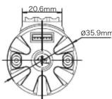
| Motor Diameter | 36 mm (1.417 in) |
| Motor Length | 62 mm (2.44 in) |
| Shaft Diameter | 5 mm (0.197 in) |
| Shaft Length | 17 mm (0.669 in) |
| Weight | 218 g (7.69 oz) |
| Number of Poles | 4 |
| Supported LiPo Cells | 2-3S (2S for 4300 KV) |
| Internal Resistance | 0.0065 Ω (3200 KV) 0.0056 Ω (3600 KV) 0.0038 Ω (4300 KV) |
| No-Load Current | 3.7 A (3200 KV) 4.1 A (3600 KV) 4.7 A (4300 KV) |
| Rotor Design | 4-pole-8-magnet staggered pole (patented) |
| Timing Adjustment Range | 20° to 40° (mechanical) |
| Default Timing | 30° |
| Housing Material | CNC machined aluminum |
| Windings Material | High purity copper |
| Output Shaft Material | High-quality alloy steel |
| Solder Tabs | U-shaped for easy soldering |
| Cooling Feature | Turbine rotor design for internal air circulation |
| Rebuild-able | Partially rebuild-able with screw-less case |
| Sensor Type | Sensored (with sensor cable) |
| Maximum Operating Temperature | 100°C (212°F) |
| Mounting Screw Size | M3, max 8 mm length |
Frequently Asked Questions - XeRun 3660 SD G2 Hobbywing
User questions about XeRun 3660 SD G2 Hobbywing
0 question about this device. Answer the ones you know or ask your own.
Ask a new question about this device
Download the instructions for your Remote control toy in PDF format for free! Find your manual XeRun 3660 SD G2 - Hobbywing and take your electronic device back in hand. On this page are published all the documents necessary for the use of your device. XeRun 3660 SD G2 by Hobbywing.
USER MANUAL XeRun 3660 SD G2 Hobbywing
natural_image
Technical line drawing of a cylindrical electric motor with stator and rotor (no text or symbols)20161215

Thank you for purchasing the XERUN 3652/3660 G2, HOBBYWING's high performance sensed brushless motor! Brushless power systems can be very dangerous, any improper use may cause personal injury and damage to the product and related devices. We strongly recommend reading through this user manual before use. Because we have no control over the use, installation, or maintenance of this product, no liability may be assumed for any damages or losses resulting from the use of this product. We do not assume responsibility for any losses caused by unauthorized modifications to our product.
01 Warnings

- Never leave this product unsupervised when it is powered on.
- Ensure all wires and connections are well insulated before connecting the motor to related devices, as short circuit will damage your motor.
- Please strictly follow the A-A, B-B and C-C wiring order when connecting an ESC to the motor.
- Never allow this product to come in contact with water, oil, fuel or other electro-conductive liquids. If this happens, stop the use of your product immediately and let it dry carefully.
- Read through the manuals of all power devices and chassis and ensure the power configuration is rational before using this unit.
- Never hit full throttle before installing the pinion, as high speed rotation may cause damage to the motor in circumstances of no load.
- Ensure all devices are well connected, in order to prevent poor connection that may cause your vehicle to lose control or other unpredictable issues such as damage to the device.
- Stop using the motor when its shell temperature exceeds 100C / 212°F ; otherwise the rotor may be demagnetized and cause irreversible damage to your motor.
02 Features
- Innovative 4-pole-8-magnet "staggered pole" rotor (Hobbywing-patented) with low cogging effect and torque pulsation greatly improves control feel around corners.
- Built-in chip for making the motor be easily identified by HOBBYWING ESCs. When pairing it with a HW 1/8th sensored ESC (i.e. XR8 SCT/Plus), the motor can work in the "sensored" mode at all times with great output linearity after the identification. The Turbo timing is allowed to be activated for higher output.
- Magnetic ring mounted on the rotor protects the motor from signal interference and guarantees its super stability in the "sensored" mode.
- With the mechanical timing adjustable from 20 degrees to 40 degrees, users are able to have different output power.
- Turbine design implemented by the rotor accelerates the internal air circulation and reduces heat.
- Rebuild-able design (partially rebuild-able) and screw-less motor case for easy routine maintenance effectively prolong the motor life and raise the motor efficiency.
• CNC machined aluminum housing, high purity copper windings, advanced rotor structure, high-quality alloy steel output shaft, high-precision bearings for high durability and smoothness. - New-style "U" solder tabs at the bottom of the motor for easy soldering and wiring.
03 Specifications
| ModelPN | KV(No-load) | Resistance | No-load Current | Motor Diameter & Length | Shaft Diameter & Length | Poles Weight Applications | LiPo | ||
| 30401050 | XERUN-3652SD-3100KV-D3.175-G2 | 3100 | 2-3S | 0.0087Ω | 2.9A | =36mm (1.417in) L=52.5mm (2.067in) | =3.175mm(0.125in) L=15mm(0.591) | 4 | 192g (6.77oz) |
| 30401052 | XERUN-3652SD-3800KV-D3.175-G2 | 3800 | 2-3S | 0.0059Ω | 3.9A | 192g (6.77oz) | |||
| 30401053 | XERUN-3652SD-4300KV-D3.175-G2 | 4300 | 2S | 0.0052Ω | 4.2A | 187g (6.60oz) | |||
| 30401054 | XERUN-3652SD-5100KV-D3.175-G2 | 5100 | 2S | 0.0035Ω | 4.7A | 192g (6.77oz) | |||
| 30401055 | XERUN-3652SD-6100KV-D3.175-G2 | 6100 | 2S | 0.0029Ω | 5.9A | 186g (6.56oz) | |||
| 30401056 | XERUN-3652SD-3100KV-D5.0-G2 | 3100 | 2-3S | 0.0087Ω | 2.9A | =5mm(0.197in) L=15mm(0.591in) | 192g (6.77oz) | ||
| 30401058 | XERUN-3652SD-3800KV-D5.0-G2 | 3800 | 2-3S | 0.0059Ω | 3.9A | 192g (6.77oz) | |||
| 30401059 | XERUN-3652SD-4300KV-D5.0-G2 | 4300 | 2S | 0.0052Ω | 4.2A | 187g (6.60oz) | |||
| 30401060 | XERUN-3652SD-5100KV-D5.0-G2 | 5100 | 2S | 0.0035Ω | 4.7A | 192g (6.77oz) | |||
| 30401061 | XERUN-3652SD-6100KV-D5.0-G2 | 6100 | 2S | 0.0029Ω | 5.9A | 186g (6.56oz) | |||
| 30401150 | XERUN-3660SD-3200KV-D5.0-G2 | 3200 | 2-3S | 0.0065Ω | 3.7A | =36(1.417in) L=62(2.44in) | =5mm(0.197in) L=17mm(0.669in) | 218g (7.69oz) | |
| 30401151 | XERUN-3660SD-3600KV-D5.0-G2 | 3600 | 2-3S | 0.0056Ω | 4.1A | 214g (7.55oz) | |||
| 30401152 | XERUN-3660SD-4300KV-D5.0-G2 | 4300 | 2S | 0.0038Ω | 4.7A | 218g (7.69oz) |

XERUN 3652/3660SD G2

XERUN 3652SD G2

XERUN 3660SD G2
XERUN 3652/3660SD G2
04 Installation & Connection

XERUN 3660SD G2
- How to Mount the Motor into a RC vehicle
M3 mounting screws (6*M3) are needed here, as the mounting holes are 5mm in depth, so we don't recommend using the M3 screws with the length exceeds 8mm to mount the motor into your vehicle. - How to Connect the Motor to an ESC
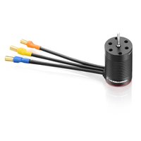
There are three power wires coming from the ESC must be soldered to the motor. They are usually color coded as Blue for Wire A, Yellow for Wire B and Orange for Wire C. When connecting the power wires between the ESC and motor, please make sure that you match ESC Wire A to Motor Phase A, ESC Wire B to Motor Phase B and ESC Wire C to Motor Phase C (this is very important). - When using a Sensored ESC, make sure the sensor cable is clean and undamaged first and then connect the sensor cable to both the ESC and the motor in the correct direction.
- When using a Sensorless ESC, swap any two wires if the motor runs in reverse.
- Recheck the Installation & Connections
Recheck the installation and all the connections before turning on the power.
05 Timing Adjustment
- (With the motor direction set to CCW), take the graduation/value after "CCW" on the motor case as the starting point when adjusting the timing. (With the reversed triangle pointing at a value/graduation,) the smaller/bigger the value,
the smaller/bigger the timing. The timing is 40 degrees (as shown in picture 1) when the motor direction is set to CCW. - (With the motor direction set to CW), take the graduation/value after "CW" on the motor case as the starting point when adjusting the timing. (With the reversed triangle pointing at a value/graduation,) the smaller/bigger the value,
the smaller/bigger the timing. The timing is 20 degrees (as shown in picture 1) when the motor direction is set to CW. • The motor timing is 30 degrees by default (as shown in picture 2). The motor timing should be within 30 to 40 degrees if you want to activate the Turbo timing. And the timing can be within 20 to 40 degrees if you have no intention to activate the Turbo timing

06 FDR/Gear Ratio Selection
It's important to select the FDR/gear ratio properly, as improper FDR/gear ratio may cause you great loss. Therefore, please choose the gear ratio by referring to the following points!
- Operating Temperature of the Motor
The motor temperature should be lower than 100° C/212°F during the operation. Temperatures above 100° C will weaken the magnet and may partly melt the coils and eventually damage the ESC (due to strong current). Therefore, the most effective way to prevent overheat is to select the right gear ratio.
- Principle of Gear Ratio Selection
To avoid potential risks such as ESC/motor damage or malfunction caused by overheat, please start with a very small pinion first and check the ESC & motor temperatures regularly throughout the run. This is the only way to guarantee that your motor won't overheat. If the motor and ESC temperatures remain stable and low in the running, then you can slowly increase the pinion size while monitoring temperatures to determine the safe gearing for your vehicle, climate and track condition. Because these elements may change, so please keep monitoring the ESC & motor temperatures to protect your electronics from damage.
07 Assembly/Disassembly
For prolonging the motor life and raising its efficiency, we recommend checking and cleaning the motor regularly. About the frequency, it depends on the times you use the motor and the track condition. Please refer to the following diagrams to assemble your motor and dismantle it in the reverse order if necessary.

Mount washers (the wave washer first, then the flat washer)

Mount the motor rotor

Mount the back end bell set

Mount screws for fastening the back end bell

Picture of the assembled motor


Brand : Hobbywing
Model : XeRun 3660 SD G2
Category : Remote control toy