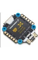
Xrotor Micro - Remote control toy Hobbywing - Free user manual and instructions
Find the device manual for free Xrotor Micro Hobbywing in PDF.


| Product Type | Remote Control Toy (Quadcopter Drone) |
| Brand | Hobbywing |
| Model | Xrotor Micro |
| Dimensions | 100 x 100 x 30 mm (without propellers) |
| Weight | 28 g (including battery) |
| Battery | 1S 3.7V 300 mAh LiPo, rechargeable |
| Flight Time | Approximately 5 minutes |
| Charging Time | Approximately 40 minutes via USB cable |
| Control Range | Up to 100 meters |
| Transmitter Frequency | 2.4 GHz |
| Main Functions | Altitude hold, Headless mode, One-key return, 3D rolls, Speed modes |
| Propeller Guard | Included for safety |
| Camera | No (FPV upgrade not available) |
| Suitable Age | 14+ years |
| Maintenance | Clean with dry cloth; avoid water and dust; store in cool dry place |
| Safety | Not for children under 3 years; fly in open area away from people and obstacles; follow local drone regulations |
| Spare Parts Availability | Propellers, motors, frame, battery available online |
| Repairability | Modular design; motors and frame user-replaceable |
| Package Contents | Drone, remote controller, battery (installed), USB charger, spare propellers (2 sets), screwdriver, manual |
Frequently Asked Questions - Xrotor Micro Hobbywing
User questions about Xrotor Micro Hobbywing
0 question about this device. Answer the ones you know or ask your own.
Ask a new question about this device
Download the instructions for your Remote control toy in PDF format for free! Find your manual Xrotor Micro - Hobbywing and take your electronic device back in hand. On this page are published all the documents necessary for the use of your device. Xrotor Micro by Hobbywing.
USER MANUAL Xrotor Micro Hobbywing
Thank you for purchasing this HOBBYWING product! Please read this declaration carefully before use, once you start to use, we will assume that you have read and agreed with all the content. Brushless power systems can be very useful in the use of the product and use of the product damage to the product and related devices, so please strictly follow the instruction during installation and use. Because we have no control over the use, installation, or maintenance of this product, no liability may be assumed to be due to the use of the product. We do not assume responsibility for any losses caused by unauthorized modifications to our product. Besides, we have the right to modify our product and make it difficult to ensure that products with un violations and notification. We, HOBBYWING, are only responsible for our product cost and nothing else as result of using our product. Regarding the possible semantic difference between two different versions of declaration, for users in maintaining their Chinese trade in order to consider it; third, for users in other regions, please take the English version as standard.
02Warnings
- Read through the manuals of all power devices and aircraft and ensure the power configuration is rational before using this unit, as improper power configuration will overload the
- When installing this unit, relevant operations like soldering, connecting will be needed, so please ensure all wires and connections are well insulated before connecting the unit to
related devices, as short circuit will damage the unit. When soldering relevant wires of the unit, please use a soldering iron with sufficient power to do the job, as poor connection may cause your aircraft to lose control or other unpredictable issues like damage to the device.
• Always keep your aircraft away from unsafe elements like obstacles, crowd, high-voltage power lines. Please fly your aircraft in the working environment as regulated in this manual.
- Always disconnect and remove batteries after use, as the ESC may drive the motor to rotate and cause unpredictable danger if it's still connected to the battery. Long-time contact will
- The open source ESC can only be flashed with the corresponding firmware (not any other firmware) when flashing or upgrading firmware, otherwise it may cause the ESC to stop
working or even damage the chip inside.
- This user manual is based on the operation manual for BLHeli_32 ARM rev32.x and only for reference. For more detailed information, please refer to the original BLHeli manual. Due to
- Please note that this product is only applicable to the multi-rotors with the diagonal wheelbase doesn't exceed 300mm, because using it beyond the specification may cause damage to the ESC or other issues. In that case, users need to take full responsibility for the consequences.
03 Features
- High performance 32-bit microprocessor with the running frequency of up to 48MHz for excellent performance.
- BLHeli_32 firmware is the third generation BLHeli, following base BLHeli and BLHeli-S
- All codes use damped light mode. Damped light does regenerative braking, causing very fast motor retardation, and inherently also does active freewheeling
- The code supports features to prevent sync loss. There are tunable parameters that can make the code run well even in the most demanding situations, although default settings will work excellently in normal operating environments.
• The code supports regular 1-2ms pulse width input, as well as Oneshot125 (125-250us), Oneshot42 (41.7-83.3us) and Multishot (5-25us).
- Dshot signaling is supported at any rate up to at least Dshot1200. The input signal is automatically detected by the ESC upon power up.
- The code also supports a beacon functionality, where the ESC will start beeping after a given time of zero throttle. This can be very useful for finding lost crafts.
- On board 5V BEC, powering different accessories such as FC, VTx, Camera and LED lights and etc.
04 Specifications
| Model | Cont. Current | Peak Current | BEC | LiPo Cells | Weight | Size | Mounting Hole |
| XRotor Micro 60A BLHeli_32 4in1 DShot1200 | 60A | 80A | 5v@0.6A | 3-6S | 15g | 52x42x6.6mm | 30.5x30.5mm |
05 User Guide
1 Definitions for Different Ports
Note: Users only need to connect the throttle control wire, 5V power wire and ground wire of the
ESC to the corresponding ports (on peripheral devices like receiver) when a single ESC needs to be
programmed.
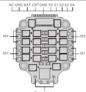
- NC: none outp
- BAT: Battery Volt monitoring port with the battery voltage is to connect to the Battery Volt monitoring port
Off Night Contr
- CTR: Amp monitoring port with the amperage of 11.75mv/A is to connect to the Amp monitoring port on flight, stationary
night controller.
• GND: Ground wire.
- 5V. 3V Power output port (for TC, camera, 3V LED light and etc.) - 51 A: Throttle signal input posts. Post 61 is for ESG M1, 62 is for M2, 63 in for M3, and 64 in for M4
- POWER INPUT: Power input soldering point, “+” for connecting the power wire, “+” for connecting the
power wire +.
2 Normal Start-up Process

flowchart
graph LR
    A["1. Power up: Time-series plot"] --> B["2. Throttle up detected (arming sequence start): Time-series plot"]
    B --> C["3. Zero throttle detected (arming sequence end): Time-series plot"]
    C --> D["After this, the motor will run."]
3 ESC/Radio Calibration

flowchart
graph LR
    A["1. Power up: Power up/Once"] --> B["2. Throttle signal detected (arming sequence start):"]
    B --> C["3. When throttle is above midstick (measuring max throttle):"]
    C --> D["4. If throttle is above midstick for 3 seconds:"]
    D --> E["5. When throttle is below midstick (measuring min throttle):"]
    E --> F["6. If throttle is below midstick for 3 seconds:"]
    F --> G["7. Throttle up detected (arming sequence start):"]
    G --> H["8. Zero throttle detected (arming sequence end):"]
At this point throttle calibration values are stored. You may remove power from the ESC, or just continue running your ESC.
Attention!
-
This is an extremely powerful brushless motor system. We strongly recommend removing your propellers for your own safety and the safety of those around you before performing
-
Available throttle calibration range is from 1000us to 2000us, and the difference between minimum and maximum throttle must be more than 140us (70us in bidirectional mode). If a calibration is done where the difference is less than 140us (70us), the maximum will be shifted so that the difference is 140us (70us).
-
Oneshot125 mode works just the same as regular 1-2ms mode, the only difference is that all timing is divided by B. And the same for Oneshot42, where all timing is further divided by 3. Multshot also works similarly, except the input signal range is 5x25us.
-
Dshot is supported at any rate, up to at least Dshot1200. When the input signal is Dshot, throttle calibration is disabled, and the throttle calibration values are ignored.
-
Input signal rates up to at least 32kHz are supported. But please note that higher input signal rates put a heavier load on the MCU, and will reduce the maximum ERPM that the ESC can handle.
06 Programming parameters
- Rampup Power:
Rampup power can be set to relative values from 3% to 150%. This is the maximum power that is allowed when ramping up at low RPMs and during start-up. For low RPMs, the maximum power to the
During startup, the actual applied power depends on throttle input, and can be lower than the maximum level set by the rampup power parameter, but the minimum level is a quarter of the maximum level. 2. Temperature Protection:
Temperature protection can be enabled or disabled. And the temperature threshold can be programmed. The programmable threshold is primarily meant as a support for hardware manufacturers to use, as different hardware can have different tolerances on the max temperatures of the various components used.
- Low RPM Power Protection:
Power limiting for low RPMs can be enabled or disabled. Disabling it can be necessary in order to achieve full power on some low KV motors running on a low supply voltage. However, disabling it increases the risk of sync loss, with the possibility of toasting motor or ESC
- Low Voltage Protection:
Low voltage protection can be set between 2.5V and 4.0V per LiPo cell. Or it can be disabled. When enabled, it will limit power applied to the motor if the battery voltage drops below the programmed threshold. This feature is primarily intended for fixed wing crafts.
- Current Protection:
Current protection can be enabled to limit current. If enabled, then current will be limited to maximum the programmed value. The reaction time of the current limiting is quite fast, so current will also be limited during accelerations.
The value given for current protection, is per ESC. So if setting limit to e.g. 40A for each of the ESCs in a quad (using BLHeliSuite32), then the total current limit for the four ESCs will be 160A.
- Motor Direction.
Motor direction can be set to fwd / rev / bidirectional / bidirectional rev.
In bidirectional mode, center throttle is zero and above is two rotation and below is reverse rotation. When bidirectional operation is selected, throttle calibration is unsabled. 7. Deman Compensation:
Demag compensation is a feature to protect from motor stalls caused by long winding demagnetization time after commutation. The typical symptom is motor stop or stutter upon quick throttle increase, particularly when running at a low RPM. As mentioned above, setting high commutation timing normally helps, but at the cost of efficiency.
Demag compensation is an alternative way of combating the issue. First of all, it detects when a demag situation occurs.
-In this situation, there is no info on motor timing, and commutation proceeds blindly with a predicted timing.
- In addition to this, motor power is cut off some time before the next commutation.
A metric is calculated that indicates how severe the demag situation is. The more severe the situation, the more power is cut off.
When delimag compensation is set to off, power is never cut.
When setting it to low or high, power is cut. For a high setting, power is cut more aggressively.
generally, a higher value of the compensation parameter gives better protection.
- Motor Timing:
Motor timing can be set between approximately 10 and approximately 310 in approximately 10 increments (actual accurate values here are 15/16ths of a degree).
Typically a medium setting will work fine, but if the motor stutters it can be beneficial to increase timing. Some motors with high inductance can have a very long commutation demagnetization time.
This can refer to the order of a short open quick discount move, particularly which coming at a low rate. According to this high, it will offer more one for de-magnitudes, and often helps
This parameter can also be set to date. In this case the code monitors being installation time, and keeps timing as low as possible without having issues with de-mag. On well-accepted motors, timing can be low in the entire power range, and thereby max power can be reduced. On not so well behaved motors, timing is increased as needed, and thereby improves margins against sync loss.
- Maximum Acceleration:
Maximum acceleration can be set between 0.1%/ms and 25.5%/ms. It can also be set to maximum, in which case acceleration is not limited. Limiting acceleration is primarily intended as a backup parameter that can be used in cases where too hard acceleration gives desyncs.
When setting to e.g. 10%/ms, it means that the power applied to the motor is not allowed to increase by more than 10% per millisecond.
- Throttle Cal Enable:
If disabled, throttle calibration is disabled.
- Minimum Throttle, Maximum Throttle and Center Throttle;
These settings set the throttle range of the ESC. Center throttle is only used for bidirectional operation. The values given for these settings are for a normal 1000us to 2000us input signal, and for the
For Dshot input signal, these settings have no effect
- Brake On Stop:
Brake on stop can be set between 1% and 100%, or disabled. When not disabled, the given brake force will be applied when throttle is zero. For nonzero throttle, this setting has no effect. This feature is primarily intended for fixed wing crafts with folding props.
On some ESCs this setting is not linearly programmable, it will just be enabled (at 100% force for any setting 1%-100%) or disabled (this applies to ESCs that have "EN/PWM" style fet drivers).
- LED Control:
LEDs can be controlled on ESCs that support it. Up to 4 LEDs can be turned on or off.
- Beep Strength:
Sets the strength of beeps under normal operation.
- Beacon Strength:
Sets the strength of beeps when beeping beacon beeps. The ESC will start beeping beacon beeps if the throttle signal has been zero for a given time. Note that setting a high beacon strength can cause hot motors or ESCs!
- Beacon Delay:
Beacon delay sets the delay before beacon beeping starts
- PWM frequency
Motor PWM frequency can be programmed between 16kHz and 48kHz. Higher PWM frequency can run motors smoother. Programmable frequency also allows for moving of small but potentially disturbing bumps in the throttle response. All ESCs have these bumps, with BLHeli_32 they can be moved in the RPM range, to a place where the system has low sensitivity to them.
07 Others
- Thermal Protection
The ESC measures temperature within the MCU and limits motor power if the temperature is too high. Motor power is limited over a range;
-If the temperature is above the threshold, motor power begins to be limited.
-If the temperature is above the threshold plus approximately 150°C, motor power is limited to 25%.
Motor power is not limited below 25%.
- Stall Protection
If the motor has attempted to start but not succeeded for a few seconds, it will stop attempting and wait for throttle to be zeroed before attempting again.
- Beacon---Beeps
If the ESC is armed and sees zero throttle for a given time, it beeps beacon beeps, which are approximately one beep per three seconds.
- Not activated ESC...Beeps
All ESCs shall be activated during manufacturing. If for some reason this is not done, the ESC will beep like this upon power up, before the normal operation beep sequence starts: "B, B, 8... (the time interval shortens gradually)". If for some reason activation has failed and the ESC is not regarded as a valid BLHeli_32 unit, the ESC will beep like this upon power up, before the normal operation beep sequence starts: "BBB, BBB, BBB" (the tone of the "BBB" changes from high to low). In this case the ESC will only accept 1-2ms nwm input signal.
- Other Relevant Information
BLHeli official website: https://github.com/bitdump/BLHeli
BLHeli32 official documentation download website: https://github.com/bitdump/BLHeli/tree/master/BLHeli_32%20ARM
Firmware: Hobbywing_XRotor_BLHeli32.

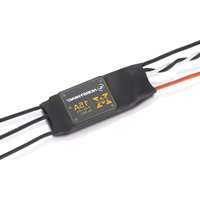
Brand : Hobbywing
Model : Xrotor Micro
Category : Remote control toy