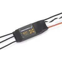
XRotor 15A - Remote control toy Hobbywing - Free user manual and instructions
Find the device manual for free XRotor 15A Hobbywing in PDF.


| Product Type | Electronic Speed Controller (ESC) for Brushless Motors |
| Brand | Hobbywing |
| Model | XRotor 15A |
| Continuous Current | 15A |
| Peak Current (10 sec) | 20A |
| BEC Output | No BEC |
| Supported LiPo | 2-4S |
| Weight | 10.5 g |
| Dimensions (L x W x H) | 47 x 17 x 8.3 mm |
| Applications | 250/300 Class Multi-rotors (e.g., 1806 or 2204 motors, 5-6 inch propellers) |
| Signal Reception Modes | Regular (1100-1940 μs) and One Shot (125-250 μs) |
| Signal Frequency (Regular Mode) | Up to 500 Hz |
| Programmable Timing | Medium (default) or High |
| Special Technology | DEO (Driving Efficiency Optimization) for improved throttle response and stability |
| Motor Compatibility | Optimized for disc-type motors |
| Cable Design | Twisted-pair throttle signal cable to reduce crosstalk |
| Protection Features | Start-up protection, over-load protection, throttle signal loss protection (0.25s) |
| Installation | Requires soldering to motor, battery, and receiver |
| Maintenance | Keep dry and free from dust; avoid overheating; remove propellers during calibration |
| Safety Warnings | Brushless systems are dangerous; improper use may cause injury. Remove propellers before calibration/programming. |
| Spare Parts & Reparability | ESC is not user-serviceable; replace if faulty. Compatible with standard brushless motors and propellers. |
| General Information | Designed for multi-rotor applications; supports both regular and One Shot signals; includes programming via throttle stick. |
Frequently Asked Questions - XRotor 15A Hobbywing
User questions about XRotor 15A Hobbywing
0 question about this device. Answer the ones you know or ask your own.
Ask a new question about this device
Download the instructions for your Remote control toy in PDF format for free! Find your manual XRotor 15A - Hobbywing and take your electronic device back in hand. On this page are published all the documents necessary for the use of your device. XRotor 15A by Hobbywing.
USER MANUAL XRotor 15A Hobbywing


Thank you for purchasing this HOBBYWING product! Brushless power systems can be very dangerous. Any improper use may cause personal injury and damage to the product and related devices. We strongly recommend reading through this user manual before use. Because we have no control over the use, installation, or maintenance of this product, no liability may be assumed for any damage or losses resulting from the use of the product. We do not assume responsibility for any losses caused by unauthorized modifications to our product. We, HOBBYWING, are only responsible for our product cost and nothing else as result of using our product.
01 Features
- Special core program for multi-rotor controllers meets various functional requirements against multi-rotors.
- Specially optimized software for excellent compatibility with disc-type motors.
- DEO (Driving Efficiency Optimization) technology significantly reduces the ESC temperature, improves the throttle response; and strengthens the stability and flexibility of multi-rotors. This ESC is quite suitable for QAVs. (The motors slow down rapidly, especially when reducing the throttle amount.)
- Compatible with "Regular" signal-receiving mode (that is the ESC can receive regular throttle
signals range from 1100μs to 1940μs) and "One Shot" signal-receiving mode (that is the ESC can receive fixed throttle signals range from 125μs to 250μs). - The twisted-pair design of the throttle signal cable effectively reduces the crosstalk produced in signal transmission and makes flight more stable.
- In "Regular" signal-receiving mode, the ESC is compatible with various flight-controllers and supports a signal frequency of up to 500Hz.
02 Specifications
| Model Con. Current | Peak Current (10s) | BEC | LiPo | Programmable item(Not Accessible in "One Shot" Mode) | Weight | Size | Applications (For reference) | |
| XRotor 15A | 15A | 20A | No | 2-4S | Timing (Medium/High) | 10.5g | 47x17x8.3 mm | 250/300 Class (Multi-rotors) |

- For 250 or 300 class multi-rotors, we recommend using 1806 size or 2204 size motors and 5 inch or 6 inch propellers. (Because bigger propellers or motors may cause the ESCs to get burnt because of overload, so users need to take the risk themselves if they persist in using propellers or motors beyond our recommendation.).
- Users cannot change the signal-receiving mode during the powering up process and the flight. If necessary, they need to change the mode on the flight controller (on the condition that the flight controller has the "One Shot" signal-receiving mode), after that, disconnect the battery and then re-connect the pack, then the ESC will complete the mode change (the ESC will automatically re-detect the type of the input throttle signals and then execute the corresponding signal-receiving mode).
03 User Guide
Throttle Calibration & ESC Programming
• After it's connected to the flight system, the ESC will automatically detect the input throttle signals every time it's powered on and then execute the corresponding signal-receiving mode.
- Users can calibrate the throttle range and change the timing advance in "Regular" signal-receiving mode but cannot do either in "One Shot" signal-receiving mode.
- In "Regular" signal-receiving mode, users need to calibrate the throttle range when they start to use a new XRotor brushless ESC or another transmitter.
- Users can change the timing advance when some abnormality occurs in ESC driving the disc-type motor or need the motor to reach a higher RPM. (Note: Medium/Intermediate Timing is the default setting.)
1 Motor Wiring

flowchart
graph TD
    A["Motor"] --> B["UBEC"]
    B --> C["Receiver"]
    C --> D["Battery"]
    D --> E["Electronic Speed Controller"]
    E --> A

This is an extremely powerful brushless motor system. We strongly recommend removing your propellers for your own safety and the safety of those around you before performing calibration and programming functions with this system.
2 Throttle Range Calibration
Turn on the transmitter, move the throttle stick to the top position.


Connect the receiver to the battery, ensure the transmitter and receiver are well bound, and then turn on the ESC.

After the motor emits two short "Beep-beep", move the throttle stick to the bottom position in 3 seconds.


Throttle Calibration completed
3 ESC Programming
Turn on the transmitter, and then move the throttle stick to the top position.

Connect the receiver to the battery and ensure the transmitter and receiver are well bound, and then power on the ESC.
The motor will beep different tones circularly

"Beep-beep-"Throttle Calibration; "Beep-beep-beep-" Intermediate Timing; "Beep-beep-beep-beep-" High Timing; If the throttle stick is moved to the bottom position 3 seconds after you hear the corresponding beeps, then the programming of that item is complete.

Programming is completed; and the ESC is ready to go.

Generally speaking, intermediate timing is applicable to most motors and it brings higher efficiency but less heat to the motors and speed controllers. High timing can increase the RPM of the motor, but it also increases the motor temperature. Please perform a test flight on the ground and ensure everything is functioning properly first, then fly your aircraft into the sky.
04 Normal Start-up Process and Protections
Turn on the transmitter and move the throttle stick to the bottom position.


The motor will emit a long *beep—"1 second after the system is connected to the battery indicating the ESC is armed and the multi-rotor is ready to go.
Start-up Protection: The ESC will shut down the motor if it fails to start the motor normally within 2 seconds by increasing the throttle value. In this case, you need to move the transmitter throttle stick back to the bottom position and restart the motor (Possible causes of this problem: poor connection/disconnection between the ESC and motor wires, propellers are blocked, etc.)
Over-load Protection: The ESC will cut off the power/output when the load suddenly increases to a very high value. Normal operation will not resume until the throttle stick is moved back to the neutral position. The ESC will automatically attempt to restart when the motor and the ESC are out of sync.
Throttle Signal Loss Protection: When the ESC detects loss of signal for over 0.25 second, it will cut off the output immediately to avoid an even greater loss which may be caused by the continuous high-speed rotation of propellers or rotor blades. The ESC will resume the corresponding output after normal signals are received.
05 Trouble shooting
| Trouble | Warning Tone | Possible Cause | Solution |
| The ESC was unable to start the motor. | "Beep beep beep..." (The motor beeps rapidly) | The throttle stick is not at the bottom position. | Move the throttle stick to the bottom position or recalibrate the throttle range. |
| The ESC was unable to start the motor. | "Beep, beep, beep......" (Time interval is 2 second) | No output signal from the throttle channel on the receiver. | Check if the transmitter and receiver are well bound; Check if the throttle wire has been properly plugged into the throttle channel on the receiver. |
| The ESC was unable to start the motor. | "Beep beep beep..." (The motor beeps rapidly) | The entire throttle range is too narrow (It's requested that the entire throttle range cannot narrower than 3 lines when designing an ESC.) | Refer to the transmitter vendor instructions and adjust the entire range of the throttle channel or re-calibrate the throttle range. |

Brand : Hobbywing
Model : XRotor 15A
Category : Remote control toy