
XRotor micro 30A BLHeli - Remote control toy Hobbywing - Free user manual and instructions
Find the device manual for free XRotor micro 30A BLHeli Hobbywing in PDF.


| Product Type | Electronic Speed Controller (ESC) |
| Brand | Hobbywing |
| Model | XRotor Micro 30A BLHeli |
| Category | Remote Control Toy / Drone Component |
| Application | Multicopter, Mini Quadcopter |
| Continuous Current | 30A |
| Burst Current (10s) | 35A |
| Input Voltage | 2-4S LiPo (7.4V - 14.8V) |
| BEC Output | 5V / 2A (linear) |
| Firmware | BLHeli_S (configurable via BLHeliSuite) |
| Processor | EFM8BB21 (48 MHz) |
| Weight | ~8 g (including wires) |
| Dimensions | 20 x 14 x 4.5 mm |
| Supported Protocols | PWM, Oneshot125, Oneshot42, Multishot, DShot150/300/600 |
| Motor Compatibility | Brushed motors (via BLHeli config) or Brushless motors (typical) |
| Connector Type | Soldered pads or 3-pin servo header (JST-SH 1.0mm) |
| Programming | Via BLHeliSuite (USB adapter required) |
| Safety Features | Over-current protection, low voltage cut-off (programmable), temperature protection |
| Maintenance | Keep dry and clean; check solder joints periodically |
| Spare Parts | None specific; user must source compatible FETs or replace whole unit |
| Repairability | Limited; FET replacement possible with soldering skills |
| Warranty | Check seller policy; typically 30 days |
Frequently Asked Questions - XRotor micro 30A BLHeli Hobbywing
User questions about XRotor micro 30A BLHeli Hobbywing
0 question about this device. Answer the ones you know or ask your own.
Ask a new question about this device
Download the instructions for your Remote control toy in PDF format for free! Find your manual XRotor micro 30A BLHeli - Hobbywing and take your electronic device back in hand. On this page are published all the documents necessary for the use of your device. XRotor micro 30A BLHeli by Hobbywing.
USER MANUAL XRotor micro 30A BLHeli Hobbywing
Thank you for purchasing this HOBBYWING product! Brushless power systems can be very dangerous. Any improper use may cause personal injury and damage to the product and related devices. We strongly recommend reading through this user manual before use. Because we have no control over the use, installation, or maintenance of this product, no liability may be assumed for any damage or losses resulting from the use of the product. We do not assume responsibility for any losses caused by unauthorized modifications to our product.
We, HOBBYWING, are only responsible for our product cost and nothing else as result of using our product.
02Warnings
- Read through the manuals of all power devices and aircraft and ensure the power configuration is rational before using this unit, as incorrect configuration may cause the ESC to overload and be damaged.
- Ensure all wires and connections must be well insulated before connecting the ESC to related devices, as short circuit will damage your ESC. And ensure all devices are well connected, (please use a soldering iron with enough power to solder all input/output wires and connectors if necessary,) as poor connection may cause your aircraft to lose control or other unpredictable issues such as damage to the device.
- Do not use this unit in the extremely hot weather or continue to use it when it gets really hot (around 105^ / 221^ ). Because high temperature will cause the ESC to work abnormally or even damage it.
- Users must always disconnect the batteries after use as the current on the ESC is consuming continuously if it's connected to the batteries (even if the ESC is turned off). The battery will completely be discharged and may result in damage to the battery or ESC when it is connected for a long period of time. This will not be covered under warranty.
03 Features
• F396 chip for great performance, 48MHz
- BLHeli open-source program implemented in the ESC supports all BLHeli functions like ESC programming and firmware upgrade via the throttle control signal cable.
- Small size combined with light weight for easy installation.
- Compatible with "Regular" signal-receiving mode and "OneShot" signal-receiving mode (that is the ESC can receive fixed throttle signals range from 125 s - 250 s ).
- The twisted-pair design of the throttle signal cable effectively reduces the crosstalk produced in signal transmission and makes flight more stable.
- Compatible with various flight-controllers and supports a signal frequency of up to 500Hz in "Regular" signal-receiving mode.
04 Specifications
| Model | Cont. Current | Peak Current (10sec) | BEC | LiPo | Weight | Size |
| XRotor micro 20A BLHeli | 20A | 30A | No | 2-4S | 6.8g | 24.0 x 13.9 x 5.5 mm |
| XRotor micro 30A BLHeli | 30A | 40A | No | 2-4S | 6.8g | 24.0 x 13.9 x 5.5 mm |
| XRotor micro 35A BLHeli | 35A | 50A | No | 3-6S | 9.5g | 36.5 x 16.7 x 5.5 mm |
05 User Guide
1 Motor Wiring

flowchart
graph TD
    A["Motor"] --> B["Electronic Speed Controller"]
    B --> C["Battery"]
    D["UBEC"] --> E["Receiver"]
    E --> B
    B --> F["Switch"]
    style A fill:#f9f,stroke:#333
    style D fill:#f9f,stroke:#333
    style E fill:#ccf,stroke:#333
    style F fill:#cff,stroke:#333
2 Normal Start-up Process

flowchart
graph LR
    A["1. Power up: Time axis"] --> B["2. Throttle up detected (arming sequence start): Time axis"]
    B --> C["3. Zero throttle detected (arming sequence end): Time axis"]
    C --> D["4. After this, the motor will run. OK"]
3 Throttle Range Calibration

flowchart
graph LR
    A["1. Power up"] --> B["2. Throttle up detected (arming sequence start):"]
    B --> C["3. Zero throttle detected (arming sequence end):"]
    C --> D["While measuring"]

flowchart
graph LR
    A["4. If throttle is above midstick for 3 seconds:"] --> B["Once"]
    B --> C["This beep sequence indicates that max throttle has been stored"]
    D["5. When throttle is below midstick (measuring min throttle):"] --> E["While measuring"]


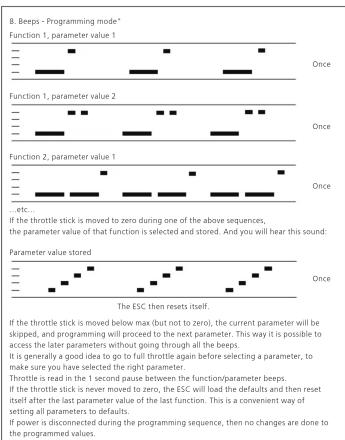
This is an extremely powerful brushless motor system. We strongly recommend removing your propellers for your own safety and the safety of those around you before performing calibration and programming functions with this system.

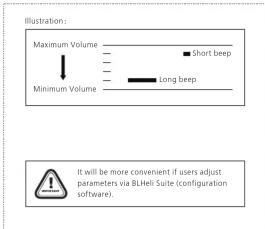
ESC Programming

flowchart
graph TD
    A["1. Power up: Time axis"] --> B["2. Throttle up detected (arming sequence start): Time axis"]
    B --> C["3. Zero throttle detected (arming sequence end): Time axis"]
    C --> D["4. If throttle is above midstick for 3 seconds: Time axis"]
    D --> E["5. When throttle is below midstick (measuring min throttle): Time axis"]
    E --> F["6. If throttle is below midstick for 3 seconds: Time axis"]
    F --> G["7. Full throttle detected after the throttle stick is moved to the top position: Time axis"]

    subgraph Time axes
        H["Once"] --> I["While measuring"]
        J["Once"] --> K["While measuring"]
        L["Once"] --> M["Once"]
        N["Once"] --> O["Once"]
        P["Once"] --> Q["Once"]
    end

    style H fill:#f9f,stroke:#333
    style I fill:#f9f,stroke:#333
    style J fill:#f9f,stroke:#333
    style K fill:#f9f,stroke:#333
    style L fill:#f9f,stroke:#333
    style M fill:#f9f,stroke:#333
    style N fill:#f9f,stroke:#333
    style O fill:#f9f,stroke:#333
    style P fill:#f9f,stroke:#333
    style Q fill:#f9f,stroke:#333
06 Programmable Items
| Function | 1 | 2 | 3 | 4 | 5 | 6 | 7 | 8 | 9 | 10 | 11 | 12 | 13 | |
| 1 | Closed loop P gain | 0.13 | 0.17 | 0.25 | 0.38 | 0.50 | 0.75 | 1.00 | 1.5 | 2.0 | 3.0 | 4.0 | 6.0 | 8.0 |
| 2 | Closed loop I gain | 0.13 | 0.17 | 0.25 | 0.38 | 0.50 | 0.75 | 1.00 | 1.5 | 2.0 | 3.0 | 4.0 | 6.0 | 8.0 |
| 3 | Closed loop mode | HiRange | MidRange | LoRange | Off | |||||||||
| 4 | Multi gain | 0.75 | 0.88 | 1.00 | 1.12 | 1.25 | ||||||||
| 5 | Startup power** | 0.031 | 0.047 | 0.063 | 0.094 | 0.125 | 0.188 | 0.25 | 0.38 | 0.50 | 0.75 | 1.00 | 1.25 | 1.50 |
| 6 | Commutation timing | Low | MediumLow | Medium | MediumHigh | High | ||||||||
| 7 | Pwm frequency | High | Low | DampedLight* | ||||||||||
| 8 | Pwm dther | Off | 7 | 15 | 31 | 63 | ||||||||
| 9 | Demag compensation | Off | Low | High | ||||||||||
| 10 | Rotation direction | Normal | Reversed | Bidirectional | ||||||||||
| 11 | Input pwm polarity | Positive | Negative |
(Those "gray background and black text" options are the factory default settings.)
*: Only enabled for some ESCs. From code rev 14.4, damped light is default on the ESCs that support it. For prior code revisions, high is default
**: Default startup power varies by ESC. Generally the default power is lower for larger ESCs. If for some reason there is an area in the overswitch unit operation is a due to loss of a
If for some reason there is an error in the eepfront/shash write operation (e.g. due to loss of power or low voltage), defaults will be loaded.
- Closed Loop P Gain: it sets the proportional gain for the rpm control loop
This setting controls the gain from speed error to motor power.
- Closed Loop I Gain: it sets the integral gain for the rpm control loop.
This setting controls the gain from integrated speed error (summed over time) to motor power.
- Closed Loop Mode: it sets the range of speeds that the control loop can operate on.
- For the high range, throttle values from 0% to 100% linearly correspond to rpm targets from 0 to 200000 electrical rpm.
- For the middle range, throttle values from 0% to 100% linearly correspond to rpm targets from 0 to 10000 electrical rpm - For the low range, throttle values from 0% to 100% linearly correspond to rpm targets from 0 to 50000 electrical rpm
For the low range, infinite values from 0 to 10 be normally set. When closed loop mode is set to Off, the control loop is disabled.
- Multi Gain: it scales the power applied to the motor for a given input
Note that this is only for PVM input, for PPM input it has no effect. Beware that a low multi gain will also limit the maximum power to the motor.
- Startup Power: it is always done with the direct startup method, which runs the motor using back emf detection from the very start.
In this mode power is given by the throttle used, but limited to a maximum level. This maximum level can be controlled with the startup power parameters. Beware that setting startup
power too high can cause excessive loading on ESC or m.
- Commutation Timing: It can be adjusted in five steps. Low is about 0°, medium low 8°, medium 15°, medium high 23° and high 30°
Typically a medium setting will work fine, but if the motor stutters it can be beneficial to change the timing
- PWM Frequency
High pwm frequency is around 20kHz, and low pwm frequency is around 8kHz.
Pwm damped light mode: it adds loss to the motor for faster retardation and it always uses high pwm frequency. It is only supported on some ESCs where fet switching is sufficiently fast
- PWM Dither: it's a parameter that adds some variation to the motor pwm off cycle length. This can reduce problems (like throttle steps or vibration) in rpm regions where the pwm
frequency is equal to harmo applied in closed loop mode.
- Demag Compensation: it's a feature to protect from motor stalls caused by long winding demagnetization time after commutation. The typical symptom is motor stop or stutter upo quick
throttle increase, particularly when running at a low rpm. As described earlier, setting high commutation timing normally helps, but at the cost of efficiency.
Generally, a higher value of the compensation parameter gives better protection.
If demag compensation is set too high, maximum power can be some
-
Rotation Direction: it can be used to reverse motor rotation.
-
Input PWM Polarity: it can be used to inverse the throttle behavior and it's intended to be used with receivers that provide negative pwm (at least some Walkeras do). When using PWM input it must be set to positive
Programming parameters that can only be accessed from configuration software (BLHeliSuite):
- Throttle minimum and maximum values for PPM input (will also be changed by doing a throttle calibration).
- Throttle center value for bidirectional operation with PPM.
- Beep strength, beacon strength and beacon delay.
- Programming by TX. If disabled, the TX can not be used to change parameter values (default is enabled).
• Thermal protection can be enabled or disabled (default is enabled).
• (The motor power will be reduced to 75% when its temperature exceeds 140°C; the power will be reduced to 50% when the temperature is above 145°C; the power will be reduced to 25%
when the temperature goes above 150°C; and the pwoer will be reduced to 0% if the temperature exceeds 155°C.)
- PWM input can be enable with leontimer below 1100
• Power limiting for low RPMs can be enabled or disabled (default is enabled). Disabling it can be necessary in order to achieve full power on some low KV motors running on a low supply
Power limiting for low in this can be enabled or disabled (default) is the voltage. However, disabling it increases the risk of toasting motor or ESC
07 others
BLHeli official website: https://github.com/bitdump/BLHeli
BLHeliSuit download: https://www.mediafire.com/folder/dx6kfaasyo24l/BLHeliSuite
This BLHeli ESC Firmware: XRotor 20A (Multi) BLHeli Rev: 14.4
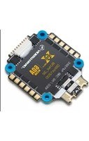
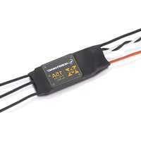
Brand : Hobbywing
Model : XRotor micro 30A BLHeli
Category : Remote control toy