
DC25/45 - Door closer Draper - Free user manual and instructions
Find the device manual for free DC25/45 Draper in PDF.


| Product Type | Door Closer |
| Brand | Draper |
| Model | DC25/45 |
| Suitable For | Interior and exterior doors |
| Dimensions (L x W x H) | Approx. 200 x 45 x 40 mm |
| Weight | Approx. 0.8 kg |
| Material | Aluminum alloy |
| Finish | Silver |
| Closing Force | Adjustable EN2-4 |
| Max Door Weight | 45 kg |
| Mounting Type | Surface mount |
| Arm Type | Slide arm |
| Adjustment | Closing speed and latch speed |
| Temperature Range | -20°C to +60°C |
| Compliance | EN1154 |
| Maintenance | Clean with damp cloth; lubricate as needed |
| Safety Note | Do not exceed max door weight |
| Spare Parts Available | Arm sets, covers |
Frequently Asked Questions - DC25/45 Draper
User questions about DC25/45 Draper
0 question about this device. Answer the ones you know or ask your own.
Ask a new question about this device
Download the instructions for your Door closer in PDF format for free! Find your manual DC25/45 - Draper and take your electronic device back in hand. On this page are published all the documents necessary for the use of your device. DC25/45 by Draper.
USER MANUAL DC25/45 Draper
IMPORTANT: PLEASE READ THESE INSTRUCTIONS CAREFULLY TO ENSURE THE SAFE AND EFFECTIVE USE OF THIS TOOL.
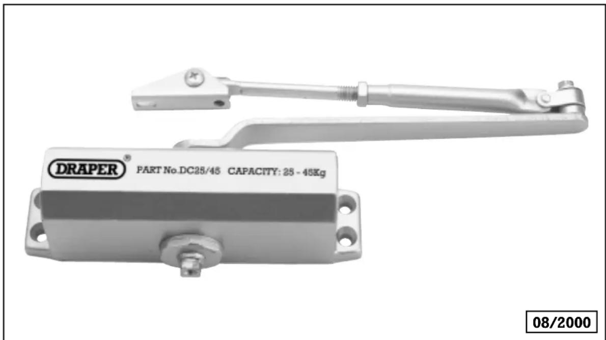
GENERAL INFORMATION
This manual has been compiled by Draper Tools and is an integrated part of the product, which should be kept with the product. This manual describes the purpose for which this product has been designed and contains all the necessary information to ensure its correct and safe use. We recommend that this manual is read before any operation of the product, before performing any kind of adjustment to the product, and prior to any maintenance tasks. By following all the general safety instructions contained in this manual, it will ensure both product and operator safety, together with longer life of the product itself.
All photographs and drawings in this manual are supplied by Draper Tools to help illustrate the operation of the product.
Whilst every effort has been made to ensure accuracy of information contained in this manual, the Draper Tool policy of continuous improvement determines the right to make modifications without prior warning.
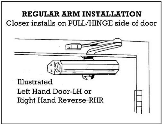
INSTALLATION INSTRUCTIONS FOR REGULAR ARM (PULL SIDE) MOUNTING
This installation process covers regular arm installations up to 180° openings.
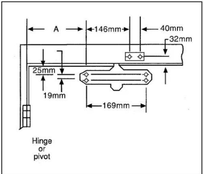
- Select the door opening angle and use the dimensions shown opposite. Mark four holes on the door for the door closer and two holes on the frame for the arm shoe.
- Drill 4mm∅ pilot holes in the door and frame for the fixings supplied.
- Fix the forearm/arm shoe assembly to the door frame using the fixings supplied.
- Attach the closer to the door using the fixings supplied.
Note: The speed adjusting valve must be positioned towards the hinged edge of the door.
- Install the main arm onto the top pinion shaft, perpendicular to the door as illustrated below. Tightly secure it in place using the screw/washer assembly supplied.
- Adjust the length of the forearm so that it is perpendicular to the door frame when assembled to preloaded main arm (see 'top view' illustration below). Secure the forearm to the main arm using the screw/washer assembly provided.
- Snap the pinion cap over the pinion shaft at the bottom of the closer unit.
- Adjust the closing speed of the door using the procedure detailed on page 5.
■STOCK No.62893 ■PART No.DC25/45 OPENING TO 120°
■DIMENSION A = 95mm
OPENING FROM 120° TO 180°
■DIMENSION A = 65mm
TYPICAL TOP VIEW
INSTALLATION
INSTALLATION INSTRUCTIONS FOR TOP JAMB (PUSH SIDE) MOUNTING
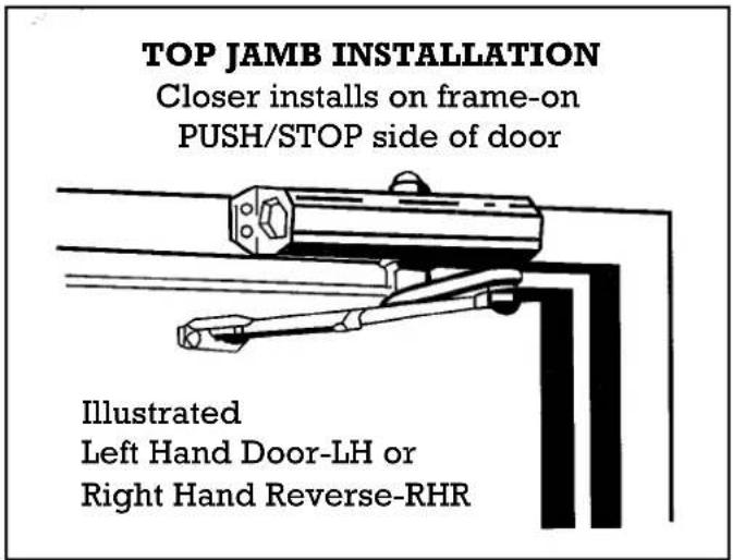
This installation process covers top jamb installations up to 180° openings.
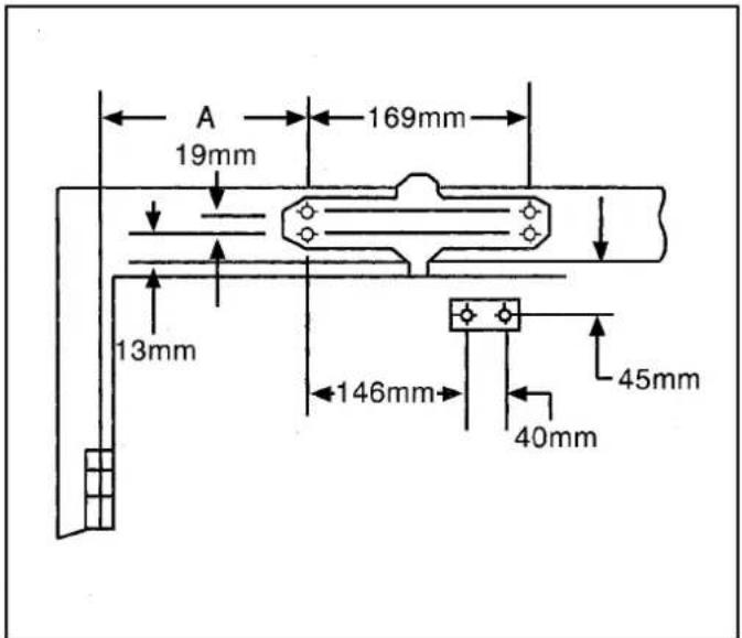
- Select the door opening angle and use the dimensions shown opposite. Mark four holes on the frame for the door closer and two holes on the door for the arm shoe.
- Drill 4mm∅ pilot holes in the door and frame for the fixings supplied.
- Fix the forearm/arm shoe assembly to the door using the fixings supplied.
- Attach the closer to the door frame using the fixings supplied.
Note: The speed adjusting valve must be positioned towards the hinged edge of the door.
- Install the main arm onto the top pinion shaft, perpendicular to the door as illustrated below. Tightly secure it in place using the screw/washer assembly supplied.
- Adjust the length of the forearm so that it is perpendicular to the door frame when preloaded with the main arm (see 'top view' illustration below). Secure the forearm to the main arm using the screw/washer assembly provided.
- Snap the pinion cap over the pinion shaft at the bottom of the closer unit.
- Adjust the closing speed of the door using the procedure detailed on page 5.
■STOCK No.62893
■ PART No.DC25/45
OPENING TO 120°
■DIMENSION A = 95mm
OPENING FROM 120° TO 180°
■DIMENSION A = 65mm
TYPICAL TOP VIEW
INSTALLATION
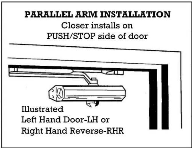
INSTALLATION INSTRUCTIONS FOR PARALLEL ARM (PUSH SIDE) MOUNTING
This installation process covers parallel arm installations up to 180° openings.
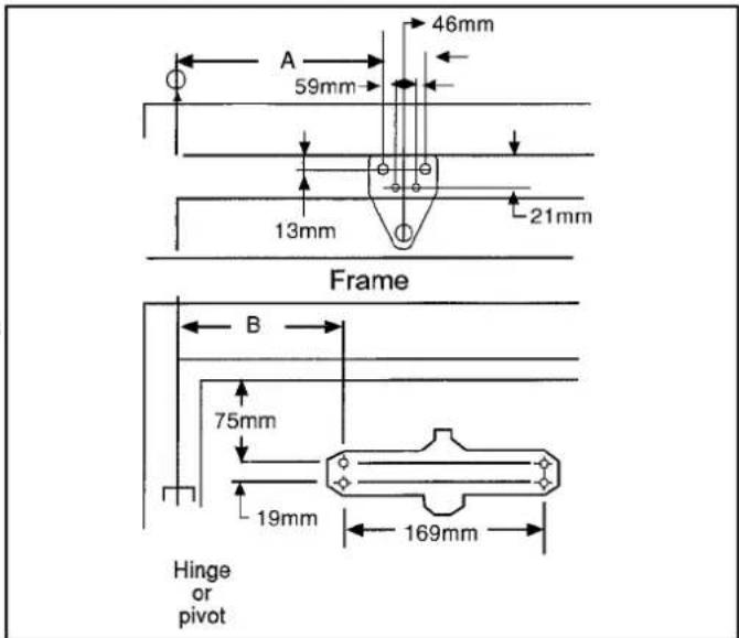
- Select the door opening angle and use the dimensions shown opposite. Mark four holes on the door for the door closer and four holes on the underside of the frame for the parallel bracket.
- Drill 4mm∅ pilot holes in the door and frame for the fixings supplied.
- Attach the closer to door using screws provided, speed adjusting valve must be positioned away from hinge edge.
- Fix parallel arm bracket to the frame using screws provided.
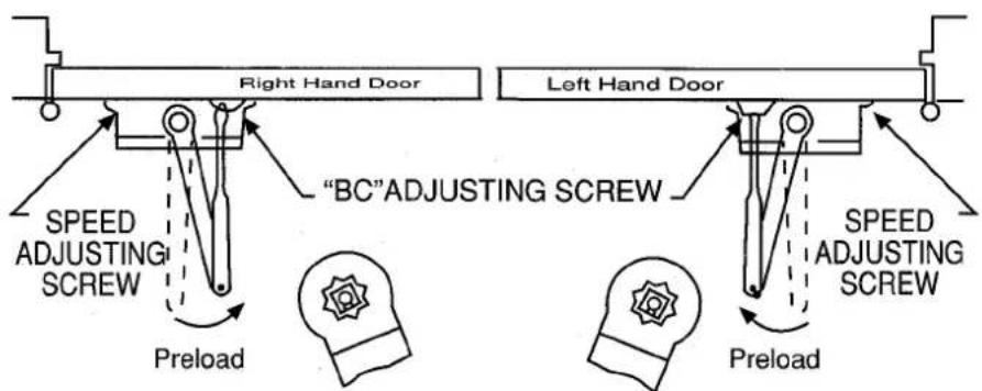
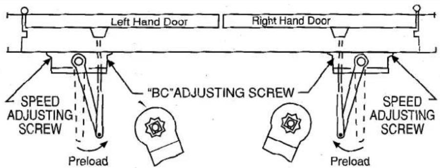
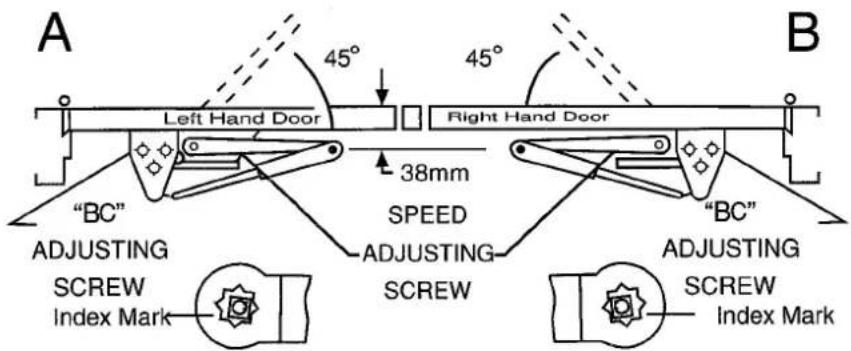
- Using a wrench on the square shaft at the bottom of the closer, rotate the shaft 100mm to 125mm towards the hinged edge of door. Hold and place the main arm of the shaft on top of the closer at the index mark, as on "top view" illustration below.
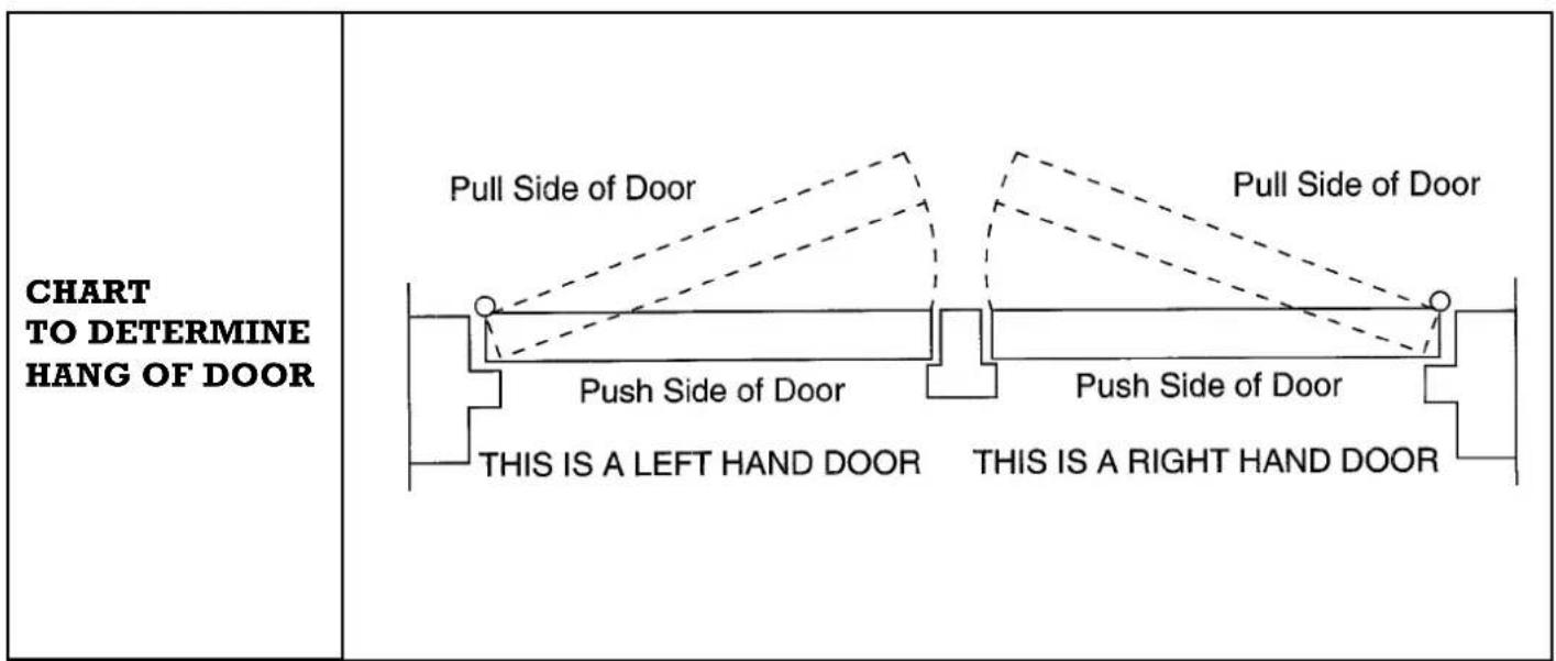
For left hand door illustration A
For right hand door illustration B
Tighten arm screw with lockwasher securely.
- Remove arm shoe from forearm and discard. Install rod end of forearm to bracket using the screw/washer assembly provided.
- Adjust forearm length so that adjustable forearm is parallel to the frame.
- Adjust the closing speed of the door using the procedure detailed on page 5.
■STOCK No.62893
■ PART No.DC25/45
OPENING TO 120°
■DIMENSION A = 149mm ■ DIMENSION B = 119mm
OPENING FROM 120° TO 180°
■DIMENSION A = 119mm ■ DIMENSION B = 89mm
TYPICAL TOP VIEW
INSTALLATION
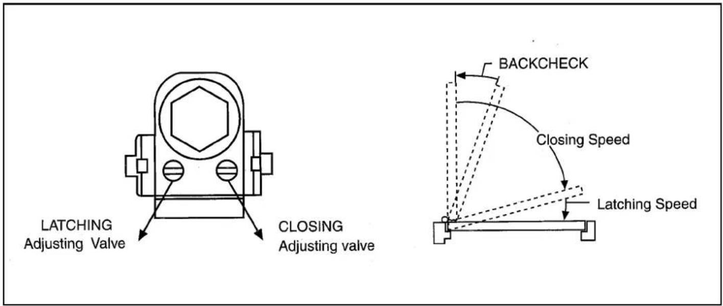
DOOR CLOSING CYCLE
CLOSING SPEED
Closing arcs are controlled by two separate speed adjusting valves. Adjust the closing speed first then adjust the latching speed.
Turn the speed adjusting valve a full rotation clockwise for a slower closing speed.
Turn the speed adjusting valve a full rotation anticlockwise for a faster closing speed.
LATCHING SPEED
Turn the speed adjusting screw a full rotation clockwise for a slower latching speed.
Turn the speed adjusting screw a full rotation anticlockwise for a faster latching speed.
CAUTION: Do not turn speed adjusting valve more than two full turns anticlockwise from its factory set position, as two speed adjusting valves could become dislodged from the door closer body, resulting with the loss of internal fluid and failure of the device.

THE TOOL COMPANY
DRAPER TOOLS LIMITED,
Hursley Road, Chandler's Ford, Eastleigh, Hants. SO53 1YF. U.K.
Helpline: (023) 8049 4344.
Sales Desk: (023) 8049 4333.
General Enquiries: (023) 8026 6355.
Fax: (023) 8026 0784.

www.draper.co.uk
e-mail: sales@draper.co.uk
YOUR DRAPER STOCKIST
Brand : Draper
Model : DC25/45
Category : Door closer