Valera 9729ES - TV Stand BDI - Free user manual and instructions
Find the device manual for free Valera 9729ES BDI in PDF.


| Product Type | TV Stand |
| Brand | BDI |
| Model | Valera 9729ES |
| Width | 60 inches |
| Depth | 20 inches |
| Height | 24 inches |
| Weight | 85 lbs |
| Material | Engineered wood with scratch-resistant laminate |
| Finish | Espresso or Black (check specific model) |
| Number of Shelves | 3 adjustable tempered glass shelves |
| Maximum TV Size | 70 inches |
| Weight Capacity (top) | 150 lbs |
| Weight Capacity (per shelf) | 30 lbs |
| Cable Management | Integrated wire management system with removable panels |
| Assembly Required | Yes, detailed instructions included |
| Warranty | Limited lifetime warranty for defects |
| Cleaning Instructions | Wipe with a soft dry cloth; avoid harsh chemicals |
| Safety Features | Anti-tip bracket included; meets CPSC standards |
| Compatible with | Most flat-screen TVs up to 70 inches |
Frequently Asked Questions - Valera 9729ES BDI
User questions about Valera 9729ES BDI
0 question about this device. Answer the ones you know or ask your own.
Ask a new question about this device
Download the instructions for your TV Stand in PDF format for free! Find your manual Valera 9729ES - BDI and take your electronic device back in hand. On this page are published all the documents necessary for the use of your device. Valera 9729ES by BDI.
USER MANUAL Valera 9729ES BDI
A - Phillips Screwdriver [Not Provided]
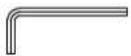
B - 4mm Hex L-Wrench
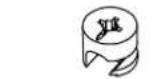
C - Cam Fastener x 4
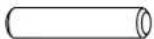
D - Dowel Pin x 8
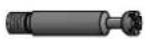
E - Cam Bolt x 4
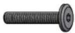
F - 1/4-20 x 38mm Machine Screw x 6

G - M6 x 16mm Machine Screw Hex Drive x 8

H - M6 x 6mm Machine Screw Hex Drive x 8
natural_image
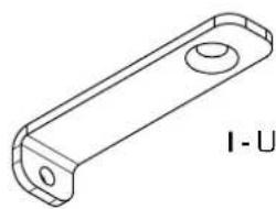
Isometric line drawing of a rectangular mechanical part with rounded corners and a central hole (no text or symbols)I - Upper Bracket x 4
natural_image
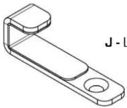
Technical line drawing of a mechanical bracket component (no text or symbols)J - Lower Bracket x 4
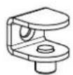
K - Shelf Clip x 4

L - #6 x 1/2" Wood Screw x 4 Phillips Drive

M - Rubber Stem Bumper x 6
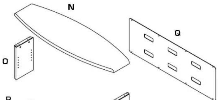
N - Top Panel x 1
0 - Side Panels x 2
P - Base Assembly x 1
Q - Back Panel x 1
R - Glass Shelves x 2
Valera is engineered for easy assembly. Carefully follow this procedure to prevent any damage.
Placement and Maintenance
Valera is designed for indoor use on level floors. Clean glass with glass cleaner, and wood veneer with a moist cloth.
natural_image
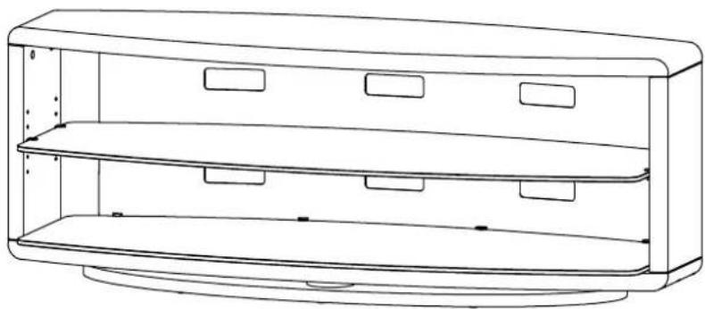
Line drawing of a multi-tiered appliance cabinet or enclosure with no text or symbolsStep 1
Unpack and Identify
Unpack and identify the components at left. The assembly workspace should be a non-marring surface such as carpet. For missing hardware pieces, please contact BDI Customer Service at customerservice@bdiusa.com. For all other concerns, please contact your BDI Retailer.
natural_image
Technical line drawings of a curved panel with labeled components (N, Q, O, P) and internal slots, no text or symbols present.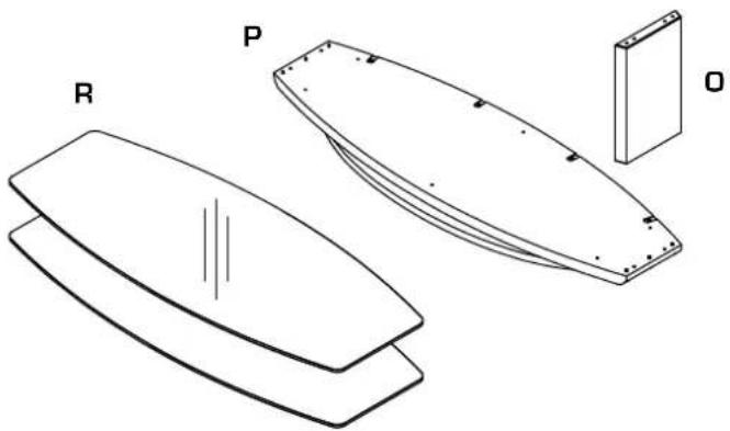
natural_image
Technical line drawing of a curved panel or casing with labeled components R, P, and O (no text or symbols beyond labels)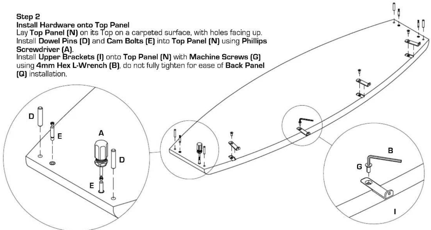
Step 3
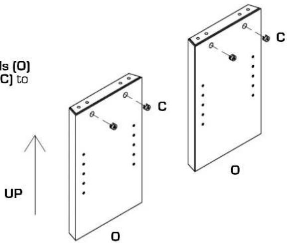
Install Hardware into Side Panels
Install Cam Fasteners (C) into Side Panels (O) as shown, align arrow on Cam Fastener (C) to point up.
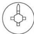
Cam Fastener (C)
Arrow to point up to start
Step 4
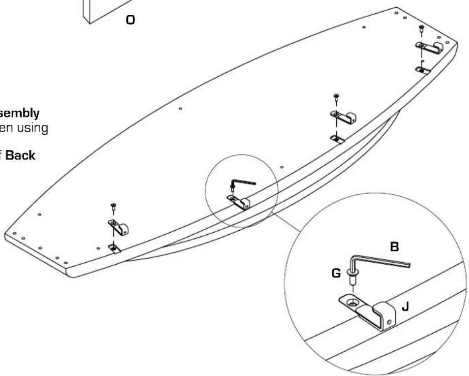
Install Hardware into Bottom Panel
Install Lower Bracket (J) into Base Assembly (P) with Machine Screws (G) and tighten using 4mm Hex L-Wrench (B).
Do not fully tighten Brackets for ease of Back Panel (Q) installation.
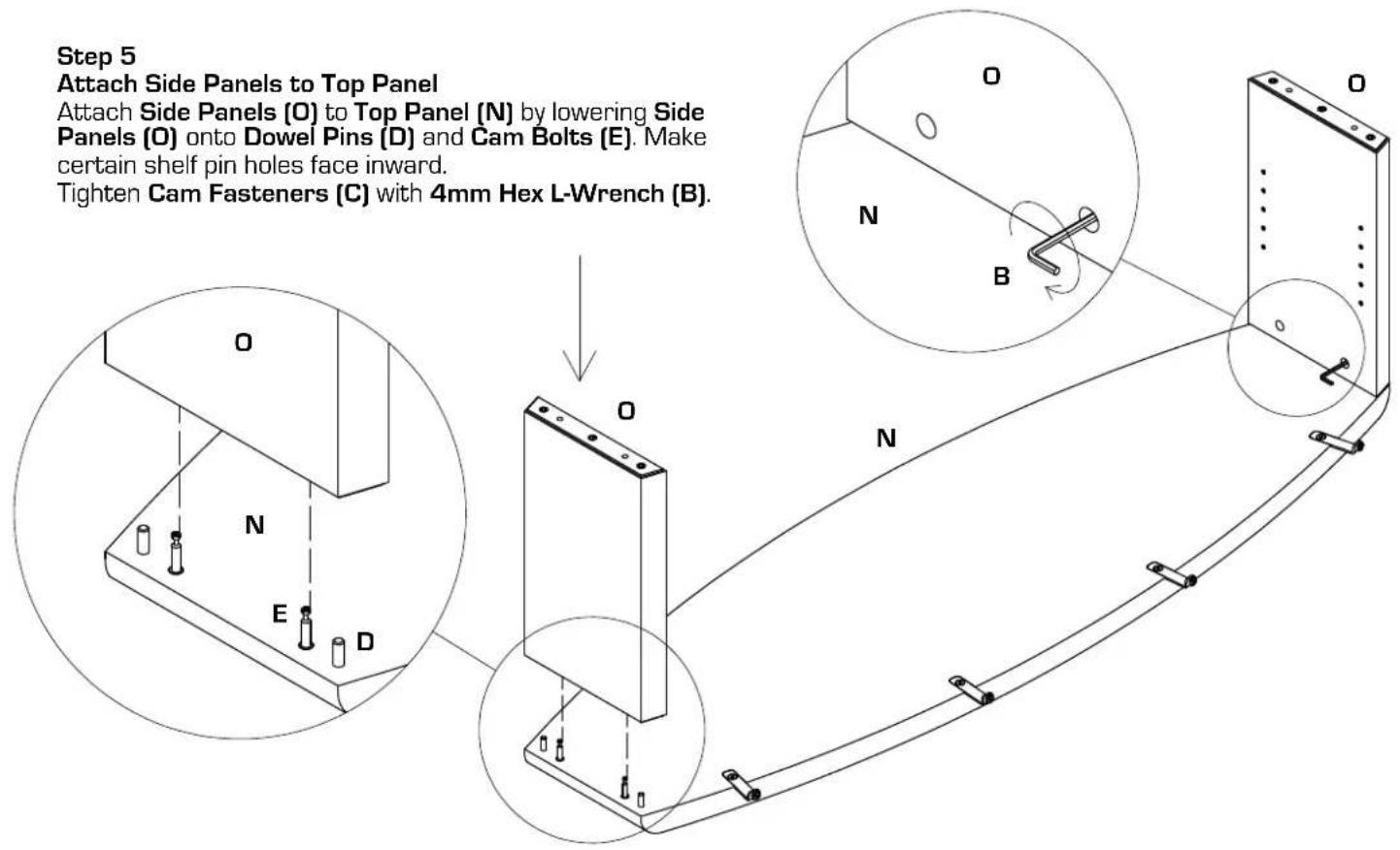
Step 6
Attach Base Assembly
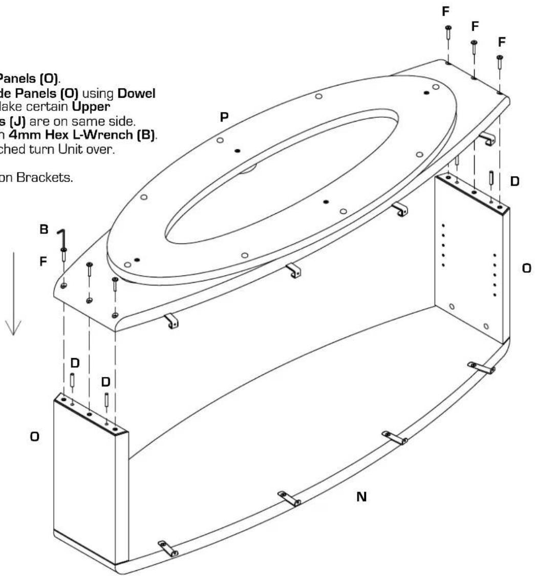
Insert Dowel Pins (D) into Side Panels (O).
Attach Base Assembly (P) to Side Panels (O) using Dowel
Pins (D) to align components. Make certain Upper
Brackets (I) and Lower Brackets (J) are on same side.
Tighten Machine Screws (F) with 4mm Hex L-Wrench (B).
After Base Assembly (P) is attached turn Unit over.
CAUTION: Do not turn unit over on Brackets.

Recommended
2-person Step
for easy
installation
Step 7
Install Back Panel
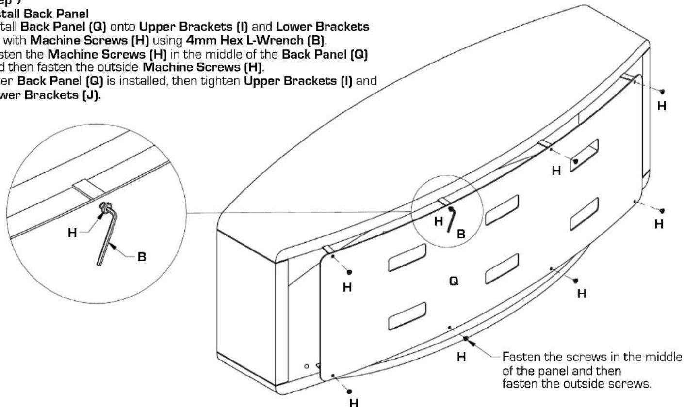
Install Back Panel (Q) onto Upper Brackets (I) and Lower Brackets (J) with Machine Screws (H) using 4mm Hex L-Wrench (B).
Fasten the Machine Screws (H) in the middle of the Back Panel (Q) and then fasten the outside Machine Screws (H).
After Back Panel (Q) is installed, then tighten Upper Brackets (I) and Lower Brackets (J).
Step 8
Install Glass Shelves
Note: Glass Shelves (R) are identical.
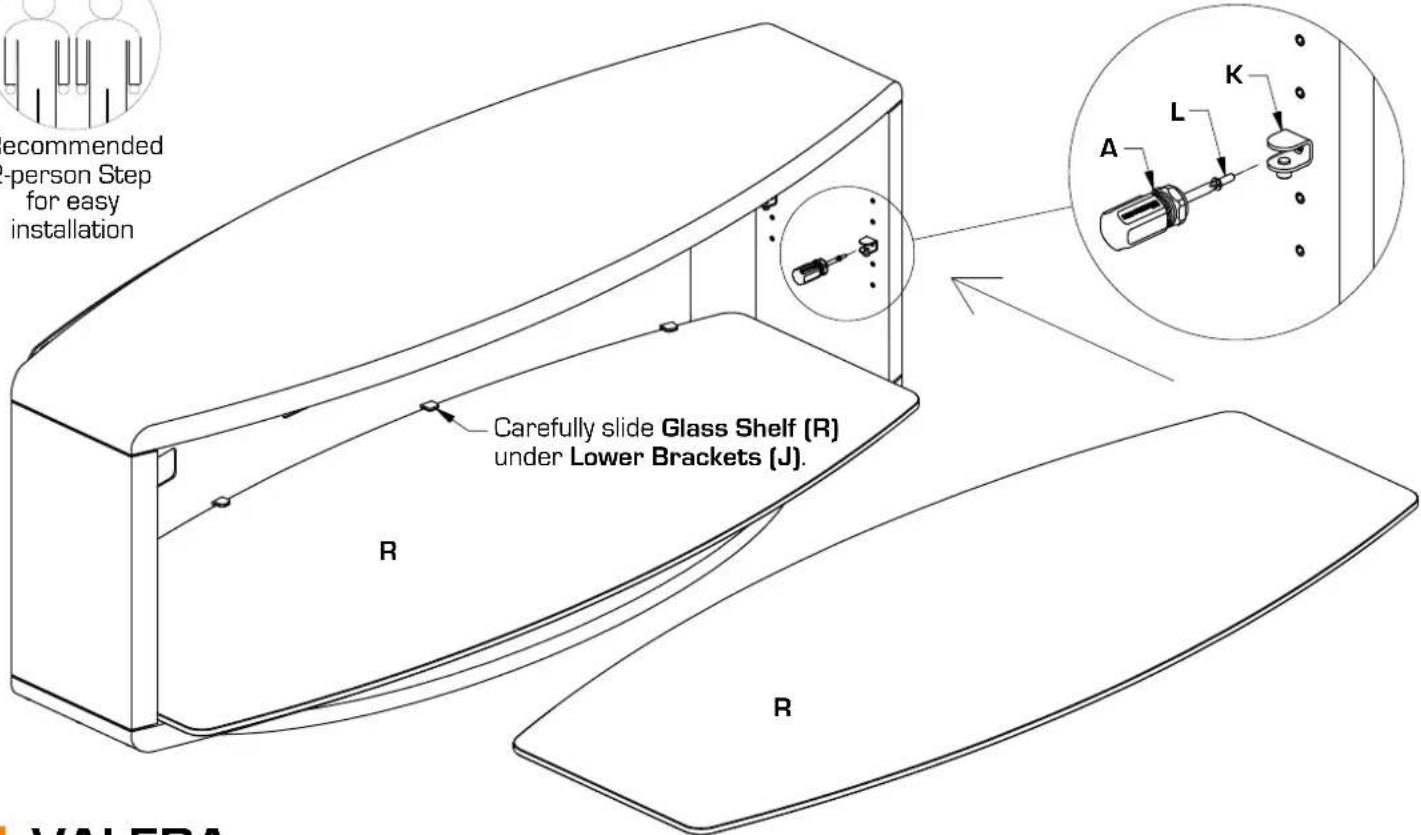
Install Rubber Stem Bumpers (M) into Base Assembly (P).
Install Lower Glass Shelf (R) onto Base Assembly (P). Slowly slide Glass Shelf (R) into place under Lower Brackets (J).
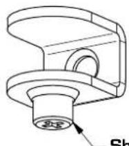
Install Shelf Clips (K) into Side Panels (O) at desired height and tighten with
Phillips Screwdriver (A). Make certain set screw on Shelf Clips (K) faces down.
Install Middle Glass Shelf (R) into Shelf Clips (K) and tighten set screws on Shelf Clips (K) with Phillips Screwdriver (A).
natural_image
Technical line drawing of a mechanical component with a circular base and curved top (no text or symbols)Shelf Clip [K]
Set screw faces down.

Recommended
2-person Step for easy installation
Brand : BDI
Model : Valera 9729ES
Category : TV Stand