PAC60 - Air conditioner Andrews - Free user manual and instructions
Find the device manual for free PAC60 Andrews in PDF.


| Product Type | Portable Split Air Conditioner |
| Model | PAC60 |
| Brand | Andrews |
| Room Unit Dimensions (HxWxD) | 1610 x 1000 x 640 mm |
| Heat Exchanger Dimensions (HxWxD) | 1085 x 820 x 605 mm |
| Room Unit Weight (wet) | 230 kg |
| Heat Exchanger Weight | 113 kg |
| Power Supply | 400V, 3-phase, 50Hz, 25A fuse |
| Nominal Power Consumption | 5500 W |
| Air Flow (High/Low) | 3500 / 2000 m³/h |
| Sound Level at 3m | 65 dBA |
| Refrigerant | R407c, <6 kg, GWP 1700 |
| Condensate Management | Automatic condensate pump |
| Thermostat | Digital, factory set at 28°C, adjustable |
| Fan Speeds | High and Low |
| Air Direction | Adjustable vertical and horizontal grilles |
| Antifreeze Mixture | 33% antifreeze, 67% water (recommended) |
| Filter Cleaning Interval | Every 2 months maximum |
| Filter Type | Washable foam filter |
| Safety Devices | High/low pressure switches, RCD, circuit breaker |
| Connection | Quick-connect water and electrical couplings |
Frequently Asked Questions - PAC60 Andrews
User questions about PAC60 Andrews
0 question about this device. Answer the ones you know or ask your own.
Ask a new question about this device
Download the instructions for your Air conditioner in PDF format for free! Find your manual PAC60 - Andrews and take your electronic device back in hand. On this page are published all the documents necessary for the use of your device. PAC60 by Andrews.
USER MANUAL PAC60 Andrews
PLEASE READ THIS LEAFLET CAREFULLY
-
DO NOT APPLY MAINS WATER PRESSURE TO PAC UNITS. ACCESS TO THE FILLING POINT FOR THE WATER CIRCULATING SYSTEM IS IN THE TOP OF THE HEAT EXCHANGER UNIT.
-
WHEN REMOVING A PAC UNIT FROM AN INSTALLATION DISCONNECT WATER QUICK COUPLINGS AT ROOM UNIT FIRST.
INTERNAL ACCESS SHOULD BE RESTRICTED TO ANDREWS TRAINED STAFF ONLY.
1) HEALTH & SAFETY AT WORK ACT 1974
Under section 6 of the above Act, it is the duty of the manufacturers and suppliers of the products for use at work to ensure, so far it is reasonably practicable, that such products are safe without risk to health when properly used and to make available to users of such products adequate information about their safe and proper operation.
Air conditioners should only be used in the manner and purpose for which they were intended and in accordance with the recommendations detailed in this leaflet. Our air conditioners have been designed, produced and inspected with safety in mind, but there are certain basic precautions which should be taken by the user and in particular attention is drawn to the safety precaution in this leaflet.
It is imperative, therefore, that all persons who may make use of our equipment have all the information and instructions they require to ensure that they are fully aware of any hazards, and that they know both the purpose and the correct manner of the use of the equipment.
GENERAL SAFETY
This equipment should only be operated by a competent adult who has read and understood these instructions.
Never operate this equipment if you are ill, feeling tired or under the influence of alcohol or drugs.
Never put anything on top of the unit or block the air inlets or outlets.
Make sure equipment is switched off and unplugged after use.
Check condition of equipment before use. If unit is showing signs of damage contact your supplier immediately.
WARNINGS!
*This unit MUST be transported and operated in the upright position at all times.
*Do not operate this equipment if it has missing, damaged, insecure guards or electrical components.
*Ensure equipment is sited on firm level ground.
*Locate away from any possible unauthorised interference.
*Ensure electrical supplies are of adequate capacity.
*The user must not undertake any service or repair of equipment.
*Ensure debris or detritus cannot be drawn into the outdoor unit fan's airflow.
ANY DOUBT CONCERNING APPLICATION / INSTALLATION CONSULT YOUR SUPPLIER.
2) INSTALLATION.
ELECTRICAL SUPPLY
All electrical installations must comply with current IEE regulations.
As standard, this unit requires a 25 Amp fused electrical supply rated at 400Volts, \~3N, 50Hz.
The unit will operate from a 32A, 3 phase wall socket.
Do not run umbilical in lying water.
Do not disconnect plugs until the mains supply has been isolated.
Ensure floor surface is adequate for the weight.
Ensure the outdoor unit (hex) is safely located on a level surface with the wheels locked, away from possible unauthorised interference.
3) SYSTEM DESCRIPTION.
The system comprises a room unit cooling section, an external heat exchanger and the two are interconnected by means of a flow and return water pipe and an electrical supply to the heat exchanger fan. The room unit is fitted with an automatic condensate disposal pump which discharges the condensate via a small plastic pipe into the base of the external heat exchanger. This pipe and all interconnecting pipes and electrics are secured together. In addition, both ends of each pipe are fitted with "quick connect" couplings that open on coupling but reseal to become water tight on disconnect.
4) AIR FLOW
The angled air outlets at the top of the standard room unit are fitted with air grilles that allow the angle of air outlet to be adjusted vertically and horizontally and, in conjunction with the fan speed control switch, the air velocity and direction can be carefully set up to obtain maximum coverage of the area being cooled without causing drafts. Care should be taken to avoid outlet air being obstructed as this will cause the air to "eddy" around the unit resulting in recirculation and short/inaccurate cycling of the machine. Ideally, cold air should be directed to create a "blanket" all across the ceiling area allowing natural convection to drop the air over the whole area at very low velocity.
5) SITING
ROOM UNIT.
Ideally, the room unit should be positioned equidistant along the shortest wall in the room blowing down the length of the room. If there is more than one unit in the same area, then they would normally be positioned side by side, and equidistant along the long wall, all pointing in the same direction. Sometimes it may be necessary to position units around the perimeter of an area but, in this case, great care should be taken to avoid one unit blowing cold air straight into another which will adversely affect the machine operation. Good and correct air flow is, perhaps, the single most important aspect of satisfactorily applying portable air conditioners. If in doubt seek the advice of your supplier.
HEAT EXCHANGER
The heat exchanger must stand external to the area being cooled and, preferably, in the outside atmosphere. It can stand freely on a flat surface. The castor wheels should be locked to prevent the heat exchanger from moving.
6)CONDENSATE. PAC60BX
In operation, the room unit is constantly condensing water vapour out of the atmosphere (reducing relative humidity). This water has to be drained away. Two automatic condensate pumps are fitted inside the PAC60BX room unit. The flexible hose outlet from the condensate pumps runs to the outside inside the cable bundle. The condensate is deposited in the base of the heat exchanger, considerable re-evaporation of this water takes place on the warm air stream passing through and around the heat exchanger, but please remember that there will also be a degree of dripping through the base of the heat exchanger.
HAVE GREAT REGARD FOR THIS CHARACTERISTIC WHEN POSITIONING THE EXTERNAL HEAT EXCHANGER.
The flexible water pipes should be routed so as to avoid any unnecessary restrictions to the flow of water inside.
7) MACHINE LINK-UP FOR PAC60BX/
Ensure the mains supply lead to the room unit is disconnected. A 15m line set to connect all services between the room unit and the external heat exchanger will have been supplied. The water pipe connections are by means of "quick connect couplers". These are simple 'push-on' connectors which, when disconnected (after pulling back sprung loaded locking ring), re-seal the water system on either side. The complete system will have been filled with the necessary amount of water/antifreeze prior to its arrival on site. A water proof 5 pin quick connect electrical coupler (push fit with screw lock ring, hand tight only), and condensate drain pipe coupler 6mm clear polythene (push fit), should also be connected. Having made the couplings, the system is operational immediately.
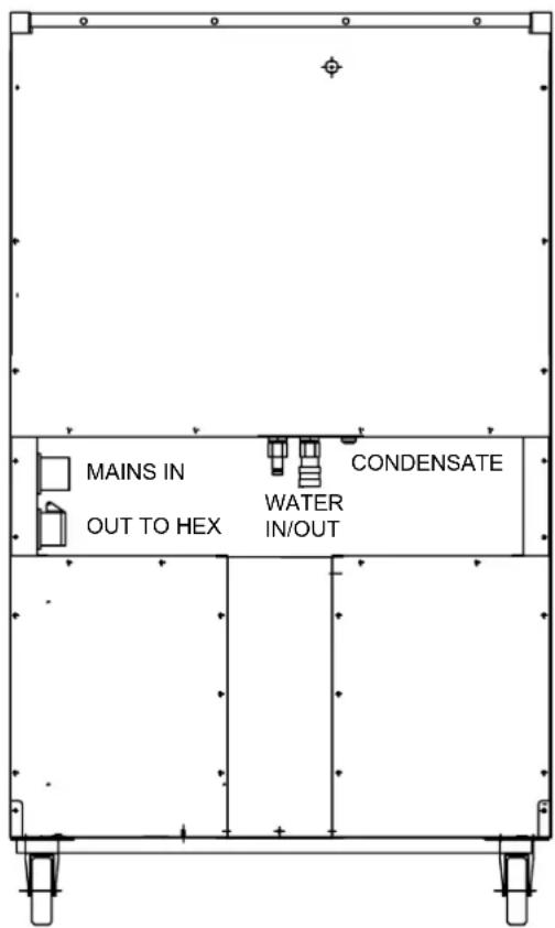
PAC CONNECTIONS

HEAT EXCHANGER CONNECTIONS
8) WATER LEVELS
The water system in the room unit will be to the correct level when delivered.
However if for some reason the level has fallen, antifreeze (33%) and water will have to be added. The header tank filler and level indication is located in the external heat exchanger.
Ensure the indoor unit is running in
cooling mode before removing the header tank cap, and as with all pressure caps, remove slowly. It is recommended that a mixture, by volume, of one part antifreeze to two parts water is utilised, this will prevent freezing down to an external temperature of -20^/-5^ .
DO NOT APPLY MAINS WATER PRESSURE TO THE SYSTEM
FIG 2

PERFORMANCE GRAPH PAC60 WATER COOLED UNIT

DATA SHEET
| UNITS | ROOM UNIT HEX | UNIT | |
| 400V 50Hz 3ph | |||
| Electrical Data: | |||
| FLA Amps 17.00 | |||
| LRA Amps 48.00 | |||
| Maximum Supply Fuse Amps 25.00 | |||
| Nominal Power Consumed Watts 5500 | |||
| Supply Voltage Limits % -10/+15 | |||
| Air Flow High/Low m3/h 3500/2000 2700 | |||
| Sound Level @ 3m | dbA | 65 | |
| Overall Dimensions | |||
| Height (Unpacked) | mm | 1610 | 1085 |
| Width (Unpacked) | mm | 1000 | 820 |
| Depth (Unpacked) | mm 640 | 605 | |
| Weight (Wet) | kg | 230 | 113 |
GAS CHARGE
The dehumidifier incorporates a hermetically sealed refeigeration circuit containing less than 6kg of refrigerant. R407c Global warming potential (GWP) 1700.
![DO NOT SCALE PRINT DIGITAL AIR STAT [AT] (NEWASIA) B BLUE BL BLACK BR BROWN GR GREY O ORANGE P PINK R RED V VIOLET W WHITE GR/B GREY/BLUE G/R GREEN/RED G/Y GREEN/YELLOW O/BL ORANGE/BLACK R/B RED/BLUE R/BL RED/BLACK R/BR RED/BROWN W/BL WHITE/BLACK WR WHITE/RED FIG.1 WIRING FOR ALTERNATIVE STAT LP SWITCH [LP] C H L R0.5 W/R 0.5 HP FAULT LAMP [LPL] HP FAULT LAMP [HPL] TANK FULL LAMP [TFL] HP SWITCH [HP] P0.5 C H L V0.5 RR 2.5 OR R 0.5 RR 0.5 RR 0.5 RR 0.5 RR 0.5 RR 0.5 RR 0.5 RR 0.5 RR 0.5 RR 0.5 RR 0.5 RR 0.5 RR 0.5 RR 0.5 RR 0.5 RR 0.5 RR 0.5 RR 0.48 RR 0.48 RR 0.48 RR 0.48 RR 0.48 RR 0.48 RR 0.48 RR 0.48 RR 0.48 RR 0.48 RR 0.48 RR 0.48 RR 0.48 RR 0.48 RR 0.48 R31 93 92 91 90 89 88 87 86 85 84 83 82 81 80 79 78 77 76 75 74 73 72 71 70 69 68 67 66 65 64 63 62 61 60 59 58 57 56 55 54 53 52 51 50 49 48 47 46 45 44 43 42 41 40 39 38 37 36 35 34 33 32 31 30 29 28 27 26 25 24 23 22 21 20 19 18 17 16 15 14 13 12 11 10 9 8 8 7 7 6 6 6 6 6 6 6 6 6 6 6 6 6 6 6 6 6 6 6 6 6 6 6 6 6 6 6 6 6 6 6 6 6 6 6 6 6 6 6 6 6 6 6 6 6 6 6 6 6 6 7 7 7 7 7 7 7 7 7 7 7 7 7 7 7 7 7 7 7 7 7 7 7 7 7 7 7 7 7 7 7 7 7 7 7 7 7 7 7 7 7 7](/content/2026/05/962550/images/ca05d1b6f5d9f386a226e23fd6d8a10e8a8f8f26d81759b659f08bf669cc1d82.jpg)
| C | S3 SWITCH DELETED | GSM | 24:02:11 | |
| B | PHASE ROTATION CONTACTORS ETC ADDED | GSM | 25:01:11 | |
| A | A S D R A W N GSM 20:12:10 | |||
| ISS C/W APPD DATE | ||||
| DRAWING CHANGE | ||||
| ● CALOREX HEAT PUMPS LTDU.C.C. | MATERIAL |
| FINISH |
![IF IN DOUBT ASK DRG No. D624950 2 POSN SWITCH [S2] (HGP) DIGITAL AIR STAT [AT] AUTOMATIC AIR SWITCH 3 POSN SWITCH [S1] (FAN ONLY) CHILL [CL] [D1][RL] MAINS DEFROST DELAY TIMER [D] 8 mins BL 0.5 R0.5 R0.5 WBL 0.5 WR 0.5 WHB 0.5 R0.5 R0.5 WR 0.5 WHB 0.5 R0.5 R0.5 WR 0.5 WHB 0.5 R0.5 R0.5 WR 0.5 WHB 0.5 R0.5 R0.5 WR 0.5 WHB 0.5 R0.5 R0.5 WR 0. R0.5 R0.5 WR 0.5 WHB 0.5 R0.5 R0.5 WR 0.5 WHB 0.5 R0.5 R0.5 WR 0.5 WHB 0.5 R0.5 R0.5 WR 0.5 WHB 0.5 R0.5 R0,0.5 R/B 0.5 BR 0.5 BR 0.5 R/B 0.5 R/B 0.5 R/B 19 RELAY 2(K) L1 2 A1 C3 C4 COMP CONTRACTOR CONDASTRATE- PUMP CONDASTRATE PUMPS MP1 L1 N1 BY 13 BRL 6 BRL 6 BRL 6 BRL 6 BRL 6 BRL 6 BRL 6 BRL 6 BRL 6 BRL 6 BRL 6 BRL 6 BRL 6 BRL 6 BRL 6 BRL 6 BRL 6 BRL 6 BRL 6 BRL 6 BRL 19 L1 N1 N1 BY 13 BRL 6 BRL 6 BRL 6 BRL 6 BRL 6 BRL 6 BRL 6 BRL 6 BRL 6 BRL 6 BRL 6 BRL 6 BRL 6 BRL 6 BRL 6 BRL 6 BRL 6 BRL 6](/content/2026/05/962550/images/de3dbd04138da6166ea9b7c6622aa7e62739777f0f69853873b111061966039f.jpg)
| TOLERANCE UNLESS SPECIFIED | TITLEWIRING DIAGRAMPAC60 + HEX60 | SHT No. CONT' DRAWN1SH2 A1GSM 10:10APPROVED DATE SCALENTS | ||||||||
| HOLES TO BS 4500 E12 | ||||||||||
| INSPECTION LEVEL DIMS | DRG No. D624950 | |||||||||

flowchart
graph TD
    A["DO NOT SCALE PRINT"] --> B["RCD"]
    B --> C["L3"]
    B --> D["L2"]
    B --> E["L1"]
    B --> F["N"]
    G["MAINS LAMP"] --> H["RL"]
    H --> I["N"]
    I --> J["N"]
    K["CONTROL CIRCUIT BREAKER TRIP/OFF= BREAK CONTACT"] --> L["PHASE ROTATION RELAY"]
    L --> M["COMPPRESSOR AUX N/C"]
    M --> N["COMPPRESSOR AUX N/O"]
    N --> O["DEFROST STAT 14 (N/O)"]
    O --> P["SOLENOID VALVE"]
    P --> Q["DEFROST LAMP"]
    R["C1 AUX 21 22 N/C"] --> S["RELAY 2"]
    T["C2 AUX 21 22 N/C"] --> S
    U["C10C18AUX 1 (N/C)"] --> V["RELAY 2"]
    W["C10C18AUX 2 (N/C)"] --> V
    X["C10C18AUX 3 (N/C)"] --> Y["RELAY 2"]
    Z["C10C18AUX 4 (N/C)"] --> Y
    AA["C10C18AUX 5 (N/C)"] --> Y
    AB["C10C18AUX 6 (N/C)"] --> Y
    AC["C10C18AUX 7 (N/C)"] --> Y
    AD["C10C18AUX 8 (N/C)"] --> Y
    AE["C10C18AUX 9 (N/C)"] --> Y
    AF["C10C18AUX 10 (N/C)"] --> Y
    AG["C10C18AUX 11 (N/C)"] --> Y
    AH["C10C18AUX 12 (N/C)"] --> Y
    AI["C10C18AUX 13 (N/C)"] --> Y
    AJ["C10C18AUX 14 (N/C)"] --> Y
    AK["C10C18AUX 15 (N/C)"] --> Y
    AL["C10C18AUX 16 (N/C)"] --> Y
    AM["C10C18AUX 17 (N/C)"] --> Y
    AN["C10C18AUX 18 (N/C)"] --> Y
    AO["C10C18AUX 19 (N/C)"] --> Y
    AP["C10C18AUX 20 (N/C)"] --> Y
    AQ["C10C18AUX 21 (N/C)"] --> Y
    AR["C10C18AUX 22 (N/C)"] --> Y
    AS["C10C18AUX 23 (N/C)"] --> Y
    AT["C10C18AUX 24 (N/C)"] --> Y
    AU["C10C18AUX 25 (N/C)"] --> Y
    AV["C10C18AUX 26 (N/C)"] --> Y
    AW["C10C18AUX 27 (N/C)"] --> Y
    AX["C10C18AUX 28 (N/C)"] --> Y
    AY["C10C18AUX 29 (N/C)"] --> Y
    AZ["C10C18AUX 30 (N/C)"] --> Y
    BA["C10C18AUX 31 (N/C)"] --> Y
    BB["C10C18AUX 32 (N/C)"] --> Y
    BC["C10C18AUX 33 (N/C)"] --> Y
    BD["C10C18AUX 34 (N/C)"] --> Y
    BE["C10C18AUX 35 (N/C)"] --> Y
    BF["C10C18AUX 36 (N/C)"] --> Y
    BG["C10C18AUX 37 (N/C)"] --> Y
    BH["C10C18AUX 38 (N/C)"] --> Y
    BI["C10C18AUX 39 (N/C)"] --> Y
    BJ["C10C18AUX 40 (N/C)"] --> Y
    BK["C10C18AUX 41 (N/C)"] --> Y
    BL["C10C18AUX 42 (N/C)"] --> Y
    BM["C10C18AUX 43 (N/C)"] --> Y
    BN["C10C18AUX 44 (N/C)"] --> Y
    BO["C10C18AUX 45 (N/C)"] --> Y
    BP["C10C18AUX 46 (N/C)"] --> Y
    BQ["C10C18AUX 47 (N/C)"] --> Y
    BR["C10C18AUX 48 (N/C)"] --> Y
    BS["C10C18AUX 49 (N/C)"] --> Y
    BT["C10C18AUX 50 (N/C)"] --> Y
    BU["C10C18AUX 51 (N/C)"] --> Y
    BV["C10C18AUX 52 (N/C)"] --> Y
    BW["C10C18AUX 53 (N/C)"] --> Y
    BX["C10C18AUX 54 (N/C)"] --> Y
    BY["C10C18AUX 55 (N/C)"] --> Y
    BZ["C10C18AUX 56 (N/C)"] --> Y
    CA["C10C18AUX 57 (N/C)"] --> Y
    CB["C10C18AUX 58 (N/C)"] --> Y
    CC["C10C18AUX 59 (N/C)"] --> Y
    CD["C10C18AUX 60 (N/C)"] --> Y
    CE["C10C18AUX 61 (N/C)"] --> Y
    CF["C10C18AUX 62 (N/C)"] --> Y
    GD["C10C18AUX 63 (N/C)"] --> Y
    DH["C10C18AUX 64 (N/C)"] --> Y
    DI["C10C18AUX 65 (N/C)"] --> Y
    DJ["C10C18AUX 66 (N/C)"] --> Y
    DK["C10C18AUX 67 (N/C)"] --> Y
    DL["C10C18AUX 68 (N/C)"] --> Y
HEX UNIT

| CIRCUIT BREAKER | OVERLOAD & SETTING |
| CONTROL | 2.0A |
| COMPRESSOR | 12.0A |
| HEX SOCKET 2.2A |
| ISS C/N APPD DATE | |||||
| DRAWING CHANGE | CALOREX.®CALOREX HEAT PUMPS LTDU.C.C. | ||||
| FINISH | |||||

flowchart
graph TD
    A["DRG No. D624950"] --> B["C1"]
    B --> C["C2"]
    C --> D["RELAY 1"]
    D --> E["S2 (HIGH)"]
    E --> F["2 POSN SWITCH"]
    F --> G["CONDENSATE PUMPS"]
    G --> H["TANK FULL LAMP"]
    H --> I["MP"]
    I --> J["FL"]
    J --> K["OUT"]
    K --> L["TIME DELAY"]
    L --> M["COM"]
    M --> N["IN"]
    N --> O["FS1"]
    O --> P["PUMP CONTROLLER"]
    P --> Q["FS2"]
    Q --> R["OUT"]
    R --> S["OUT"]
    S --> T["OUT"]
    T --> U["OUT"]
    U --> V["OUT"]
    V --> W["OUT"]
    W --> X["OUT"]
    X --> Y["OUT"]
    Y --> Z["OUT"]
    Z --> AA["OUT"]
    AA --> AB["OUT"]
    AB --> AC["OUT"]
    AC --> AD["OUT"]
    AD --> AE["OUT"]
    AE --> AF["OUT"]
    AF --> AG["OUT"]
    AG --> AH["OUT"]
    AH --> AI["OUT"]
    AI --> AJ["OUT"]
    AJ --> AK["OUT"]
    AK --> AL["OUT"]
    AL --> AM["OUT"]
    AM --> AN["OUT"]
    AN --> AO["OUT"]
    AO --> AP["OUT"]
    AP --> AQ["OUT"]
    AQ --> AR["OUT"]
    AR --> AS["OUT"]
    AS --> AT["OUT"]
    AT --> AU["OUT"]
    AU --> AV["OUT"]
    AV --> AW["OUT"]
    AW --> AX["OUT"]
    AX --> AY["OUT"]
    AY --> AZ["OUT"]
    AZ --> BA["OUT"]
    BA --> BB["OUT"]
    BB --> BC["OUT"]
    BC --> BD["OUT"]
    BD --> BE["OUT"]
    BE --> BF["OUT"]
    BF --> BG["OUT"]
    BG --> BH["OUT"]
    BH --> BI["OUT"]
    BI --> BJ["OUT"]
    BJ --> BK["OUT"]
    BK --> BL["OUT"]
    BL --> BM["OUT"]
    BM --> BN["OUT"]
    BN --> BO["OUT"]
    BO --> BP["OUT"]
    BP --> BQ["OUT"]
    BQ --> BR["OUT"]
    BR --> BS["OUT"]
    BS --> BT["OUT"]
    BT --> BU["OUT"]
    BU --> BV["OUT"]
    BV --> BW["OUT"]
| TFL | TANK FULL LAMP LAMPE 'TANK VOL' | VOYANT DE REMPLISSAGE DU BAC A CONDENSAT | |
| FS1 | FLOAT SWITCH HIGH LEVEL | SCHWIMMERSCHALTER HOHER STAND | INTERRUPTEUR A FLOTTEUR NIVEAU HAUT |
| FS2 | FLOAT SWITCH LOW LEVEL | SCHWIMMERSCHALTER NIEDRIGER STAND | INTERRUPTEUR A FLOTTEUR NIVEAU BAS |
| DL DEFROST LAMP LAMPE 'ENTEISEN' VOYANT DEGIVRAGE | |||
| CL CHILL LAMP LAMPE 'KUHLEN' | VOYANT REFROIDISSEMENT | ||
| RL MAINS (OR RUN) LAMP | LAMPE 'STROMEIN' ODER 'LAUF' | VOYANT SECTEUR (FONCTIONNEMENT) | |
| HPL HIGH PRESSURE FAULT LAMP | STORUNGS LAMPE 'HOCHDRUCK' | VOYANT SECURITE HAUTE PRESSION | |
| LPL LOW PRESSURE FAULT LAMP | STORUNGS LAMPE 'NIEDERDRUCK' | VOYANT SECURITE BASSE PRESSION | |
| F1 CONTROL FUSE | KONTROLLSICHERUNG | FUSIBLE PRINCIPAL | |
| F2 CONDENSATE FUSE | KONDENSATSICHERUNG | FUSIBLE CONDENSAT | |
| B CONTACTOR | SCHALTSCHUTZ | CONTACTEUR | |
| FT DEFROST THERMOSTAT | VEREISUNGSSCHUTZ THERMOSTAT | THERMOSTAT DE DEGIVRAGE | |
| S1 FAN MODE SWITCH | GEBLASESCHALTER | SELECTEUR DE MODE DU VENTILATEUR | |
| S2 FAN SPEED SWITCH | SCHALTER VENTILATORGESCHWINDIGKEIT | COMMUTATEUR VITESSE VENTILATEUR | |
| HP HIGH PRESSURE SWITCH | HOCHDRUCKSCHALTER | REINITIALISATION DEFAULT HAUTE PRESSION | |
| LP LOW PRESSURE SWITCH | NIEDERDRUCKSCHALTER | REINITIALISATION DEFAULT BASSE PRESSION | |
| D DELAY TIMER | VERZOGERUNGSRELAIS | TEMPORISATEUR | |
| K RELAY | RELAIS | RELAIS | |
| MC COMPRESSOR MOTOR | KOMPRESSORMOTOR | COMPRESSEUR | |
| MV FAN MOTOR | VENTILATORMOTOR | MOTEUR DU VENTILATEUR | |
| C1 COMPRESSOR CAPACITOR | KONDENSATOR KOMPRESSOR | CONDENSATEUR DU COMPRESSEUR | |
| C2 FAN CAPACITOR | KONDENSATOR VENTILATOR | CONDENSATEUR DU VENTILATEUR | |
| C3 HARD START CAPACITOR | HARTSTARTKONDENSATOR | CONDENSATEUR DEMARRAGE DIRECT | |
| Y SOLENOID VALVE | MAGNETVENTIL | VANNE ELECTROMAGNETIQUE | |
| AT AIR THERMOSTAT | LUFT THERMOSTAT | THERMOSTAT AIR | |
| MP CONDENSATE PUMP | KONDENSATPUMPE | POMPE A CONDENSAT | |
| TOLERANCE UNLESS SPECIFIED | TITLECIRCUIT DIAGRAMPAC60 + HEX60 | SHT No.2 | CONT--- | DRAWNGSM 10: | APPROVED0:10 | NFS | DATE | SCALE | ||||
| HOLES TO BS 4500 E12 | ||||||||||||
| INSPECTION LEVEL | DIMS | DRG No. D624950 | ||||||||||
10) OPERATING INSTRUCTIONS.
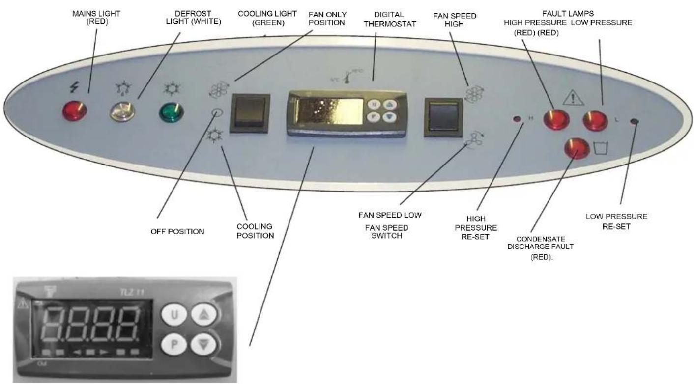
The Control Panel on the room unit is illustrated below,
a) Plug in the room unit mains cable, and switch on electricity, red mains light will illuminate.
b) Select "Fan Only" with the mode switch. The fan will start.
c) Select "Fan Speed", with the fan speed switch, high or low depending on air velocity required.
d) Select "Cooling" with the mode switch.
e) The PAC60 is fitted with a digital thermostat which is factory preset at 28^ C. With the PAC set like this the PAC starts to cool at 29^ C and will stop cooling at 28^ C.
Changing the set point.
Thermostat
Press P button once and release. Set Point and set point value (28) will be displayed alternately.
Press the ▲ or ▼ key to change the value of the set point. Once the desired value is displayed press P again to memorise the value. Cooling starts at 1°C above the new set point value and stops at the set point.
After a delay of 5 to 10 minutes the amber "Cooling" light will illuminate and the machine will proceed to cool the air.
FIG.3 CONSOLE LABEL/ MARKING
11) ROUTINE MAINTENANCE
The air filter must be kept clean, never allow to become choked with dust or dirt. If allowed to do so, the performance of the unit will become impaired, resulting in loss of air flow, freezing up of the evaporator coil and possible component damage.
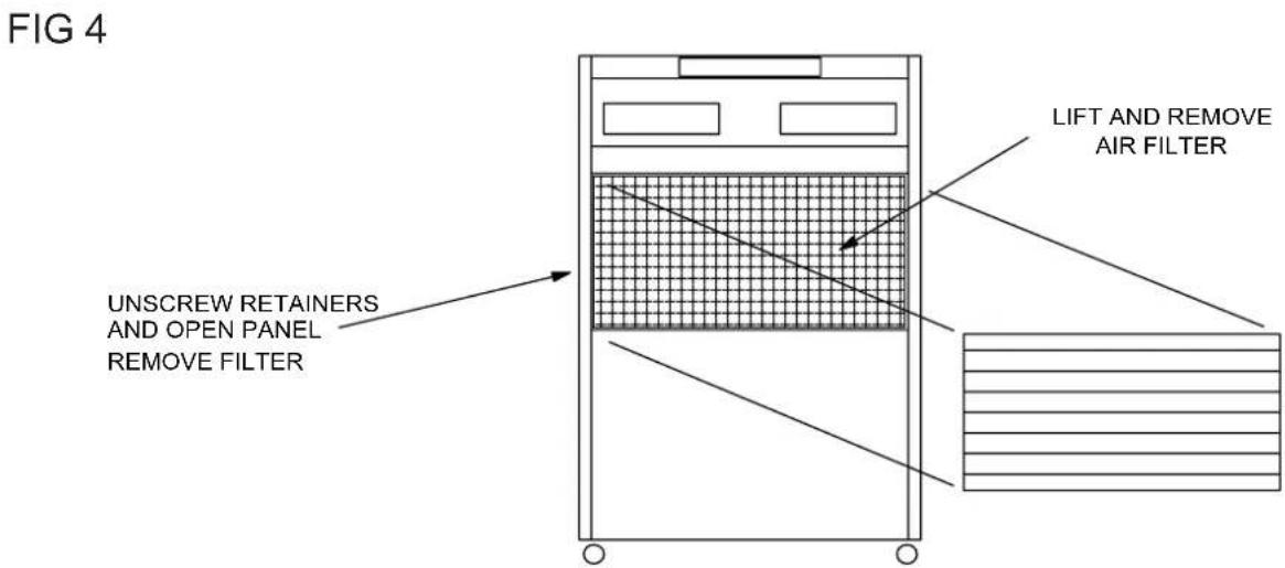
PAC60BX Lift out the return air grille on the front face of the unit, Fig 4. On refitting the filter ensure that it is correctly positioned covering the whole rear face of the grille. The filter (see Fig. 4) can be washed in warm, soapy water, rinsed and shaken dry before replacement. Frequency of cleaning depends upon application and can only be determined by the user. However, you should never allow more than two months to elapse between cleaning. The probable life of the filter will be about one year and spares are available from the supplier of the unit itself. Failure to have filter fitted during operation will cause serious damage.
The refrigeration circuit inside the room unit is fitted with a HIGH and a LOW pressure sensing switch. They are both manually resettable. A pencil or screwdriver with gentle pressure on the knob behind is all that is required to re-set.
Necessary access is provided via the control console of the PAC60BX.
HOWEVER, DO NOT ATTEMPT TO RESET WITHOUT FIRST DISCOVERING WHY THE TRIP OCCURRED IN THE FIRST PLACE.
12) MACHINE NOT WORKING?
ONLY A COMPETENT ELECTRICIAN SHOULD ATTEMPT TO RECTIFY ELECTRICAL SUPPLY PROBLEMS. DO NOT REMOVE ANY PANELS FROM THE MACHINE.
Problem - No air flow from room unit.
Diagnosis -Red "MAINS" light off.
Cure - Turn on electricity and/or check mains supply circuit breaker and the R.C.D situated in the electric box in the PAC 60BX unit.
Problem - No air flow from room unit.
Diagnosis - Red "MAINS" light on, White "DEFROST" light on.
Cure - Machine in defrost mode, do not adjust anything, machine will revert to normal run after 10 mins.
Problem - Insufficient air flow from room unit.
Diagnosis - Blocked air filter.
Cure - Clean filter
Problem - No cooling.
Diagnosis - Green "COOLING" light off.
Cure - Change value of set point on digital thermostat to a lower setting.
Problem - No cooling.
Diagnosis - Red "ATTENTION" Red High Pressure fault light illuminated. High pressure trip.
Cure - Press "+" button to re-set and check for :- Shortage of water ... top up.
External heat exchanger unit mounted in very high temperature?
Water frozen? Add glycol (33%).
13 ERROR CODES ASSOCIATED
WITH DIGITAL THERMOSTAT.
External heat exchanger coil blocked with dirt.. clean.
Problem - No Cooling.
Diagnosis - Red "ATTENTION" Red Low Pressure fault light illuminated. Low pressure trip.
Cure - Press, "-" button to re-set and check for No air flow, blocked filter?
Evaporator blocked with ice. Very low air temperature?
Problem - No cooling.
Diagnosis - Red Condensate discharge fault) light illuminated. High level condensate trip.
Cure - Condensate pump not reducing water level. Kink in condensate tube between room unit and external heat exchanger? Leak inside room unit. Sump filter located in heat exchanger unit blocked. Condensate tube frozen.
| DISPLAY ERROR ACTION | |||
| E1 OR -E1 | PROBE INTERRUPTED OR SHORT CIRCUIT | VERIFY CORRECT CONNECTION BETWEEN PROBE AND STAT, THEN VERIFY CORRECT FUNCTIONING OF PROBE. | |
| EEPr | INTERNAL | MEMORY | CHECK AND IF NECESSARY REPROGRAMME ERRORTHE PARAMETERS FUNCTION |

ANDREWS
AIR CONDITIONING
AIR TREATMENT DIVISION
Andrews Sykes Hire Limited
Premier House, Darlington Street, Wolverhampton WV1 4JJ
Telephone 01902 328700
Fax 01902 422466
- GENERAL SAFETY
- WARNINGS!
- 3) SYSTEM DESCRIPTION.
- 4) AIR FLOW
- 5) SITING
- ROOM UNIT.
- HEAT EXCHANGER
- 6)CONDENSATE. PAC60BX
- 7) MACHINE LINK-UP FOR PAC60BX/
- 8) WATER LEVELS
- DO NOT APPLY MAINS WATER PRESSURE TO THE SYSTEM
- GAS CHARGE
- 10) OPERATING INSTRUCTIONS.
- Thermostat
- 11) ROUTINE MAINTENANCE
- 12) MACHINE NOT WORKING?
- ONLY A COMPETENT ELECTRICIAN SHOULD ATTEMPT TO RECTIFY ELECTRICAL SUPPLY PROBLEMS. DO NOT REMOVE ANY PANELS FROM THE MACHINE.
- ERROR CODES ASSOCIATED
- ANDREWS
- AIR CONDITIONING
Brand : Andrews
Model : PAC60
Category : Air conditioner