ET15 - Air conditioner Andrews - Free user manual and instructions
Find the device manual for free ET15 Andrews in PDF.


| Product Type | Portable Air Conditioner |
| Brand | Andrews |
| Model | ET15 |
| Cooling Capacity | 12000 BTU (3.5 kW) |
| Power Supply | 220-240 V ~ 50 Hz |
| Power Consumption (Cooling) | 1050 W |
| Dimensions (W x D x H) | 30 x 40 x 70 cm |
| Weight | 25 kg |
| Refrigerant | R290 (Propane) |
| Air Flow Rate | 350 m³/h |
| Noise Level | ≤ 65 dB(A) |
| Operating Modes | Cool, Fan, Dehumidify |
| Thermostat Range | 16°C - 32°C |
| Timer | 1 - 24 hours |
| Remote Control | Yes (included) |
| Drainage | Continuous or manual |
| Filter Type | Washable mesh filter |
| Maintenance | Clean filter every 2 weeks; drain condensation as needed |
| Safety Features | Auto shut-off, overload protection, tip-over switch |
| Repairability | Replaceable filter, accessible components (fan, compressor) |
| Warranty | 2 years (parts and labor) |
Frequently Asked Questions - ET15 Andrews
User questions about ET15 Andrews
0 question about this device. Answer the ones you know or ask your own.
Ask a new question about this device
Download the instructions for your Air conditioner in PDF format for free! Find your manual ET15 - Andrews and take your electronic device back in hand. On this page are published all the documents necessary for the use of your device. ET15 by Andrews.
USER MANUAL ET15 Andrews
Portable Air Conditioning

natural_image
Exterior view of a modern air conditioning unit (no signage or text visible on the device itself)Operating Instructions & Safety Guide

ANDREWS
AIR CONDITIONING
General Safety
Keep children and animals away from air conditioning units. Never leave them alone in a room where the units in use.
This equipment should only be used by a competent person who has read and understood these instructions.
Never operate this equipment if you are ill, feeling tired or under the influence of alcohol or drugs.
Keep the Air Conditioning vents clear of all obstructions.
Never put anything on top of the unit or block the air outlets.
Make sure equipment is switched off and unplugged after use
Never leave switched on or unattended.
Do not use the unit where sunlight is shining directly onto it.
Check condition of equipment before use. If unit is showing signs of damage contact your supplier immediately.
Electrical Safety
This unit requires a 230 volt electrical supply. It plugs into a standard BS1363 domestic socket.
Always inspect plugs and leads for damage before plugging into the supply - DO NOT USE IF ANY DAMAGE IS FOUND
Ensure cables are run as not to cause a hazard.
If an extension lead is used, ensure it is of the correct standard, and fully uncoiled when being used.
Do not lay electrical cables in wet / damp areas.
Do not move equipment whilst operating.
Do not pull equipment by its cable.
It is recommended that electrical equipment is used via a suitable RCD. WARNING!
This unit MUST be transported and operated in the upright position at all times
Electrical Supply
As standard this unit requires a 13 amp fused electrical supply rated at 230v 1ph 50hz. The unit will operate from a standard 13A wall socket. The size of any extension cable that may be 2-5mm2 minimum up to a maximum length of 10 metres. For longer lengths 4mm2 cable must be used. If the cable is on a 'cable drum' then ensure that it is completely unwound; serious complications will occur otherwise. NOTE: most domestic proprietary extension cables are 1.5mm². This is not sufficient.
Air Cooled Units
The system comprises, a room unit fitted with either a fixed or flexible ducting system as specified by the customer. Condensate is collected, either in the units internal tank and emptied by the user or pumped using an optional condensate disposal unit (fig. 1).
Air Flow
The angled air outlets at the top of the room unit are fitted with air grilles that allow the angle of air outlet to be adjusted vertically and horizontally and, in conjunction with the fan speed control switch, the air velocity and direction can be carefully set up to obtain maximum coverage of the area being cooled without causing drafts. Care should be taken to avoid outlet air being obstructed as this will cause the air to 'eddy' around the unit resulting in recirculation and short/inaccurate cycling of the machine. Ideally, cold air should be directed to create a 'blanket' all across the ceiling area allowing natural convection to drop the air over the whole area at very low velocity. An alternative top panel with twin 7" ducts is available.
Siting of ET 15
Ideally, the room unit should be positioned equidistant along he shortest wall in the room blowing down the length of the room. Of there is more than one unit in the same area, then they would normally be positioned side by side, and equidistant along the long wall, all pointing in the same direction. Sometimes it may be necessary to position units around the perimeter of an area but, in this case, great care should be taken t avoid one unit blowing cold air straight into another which will adversely affect the machine operation. Good and correct air flow is, perhaps, the single most important aspect of satisfactory applying portable air conditioners. If in doubt seek the advice of your supplier.
Exhaust Tubes Air Cooled Unit
The exhaust tube(s) must carry the air to an area external to that being cooled, preferably in the outside atmosphere (fig. 1).


Operating Instructions - ET15

SMALL WATER & AIR COOLED UNITS
Operation Instructions
The control panel on the room unit is illustrated above
Revolve thermostat knob fully CLOCKWISE to the number '8' position
Plug in the room unit mains cable, and switch on the electricity, red mains light will illuminate.
Select 'Fan Only' with the mode switch. The fan will start.
Select 'Fan Speed' with the fan speed switch, high or low depending on air velocity required.
Select 'Cooling' with the mode switch, and revolve the thermostat knob fully ANTI-CLOCKWISE to he number '1' position. After a delay of 10 mins the green 'Cooling' light will illuminate and the machine will proceed to cool the air.
Monitor the room temperature and when it has reduced to the desired level, very slowly revolve the thermostat knob back, clockwise until the green 'Cooling' light goes out. The room unit will now control the room temperature cooling automatically at this setting.
Routine Maintenance
The air filter must be kept clean, never allow to become choked with dust or dirt. If allowed to do so, the performance of the unit will become impaired, resulting in loss of air flow, freezing up the evaporator coil and possible component damage.
Accessing the Filter
On machines fitted with a hinged lower panel, open panel. The filter is located on front of the evaporator. A second filter is fitted to the rear panel on all air cooled machines (fig. 5 & 6).
The filter can be washed in warm, soapy water, rinsed and shaken dry before replacement. Frequency of cleaning depends upon application and can only be
determined by the user. However, you should never allow more than two months to elapse between cleaning. The probable life of the filter will be about one year and spares are available from the supplier of the unit itself. Failure to have filter fitted during operation will cause serious damage.
| Problem Likely | Cause Solution | |
| No cooling Amber | ‘ATTENTION’ light illuminated. High level condensate trip. | Condensate pump not reducing water level Kink in condensate tube between room unit and external heat exchanger? Leak inside room unit. Pump filter inside room unit blocked. Condensate tube frozen. |
| No cooling Amber | ‘ATTENTION’ light illuminated. Bottle fitted switch trip. | ensure bottle fitted correctly. |
| No cooling Amber | ‘CONTAINER FULL’ light illuminated. High level condensate trip. | On machines without a removable bottle, as above. On machines with a bottle, remove container and replace correctly.To empty the condensate bottle: Unscrew the 2 x thumb screws on the front panel (fig. 2).The front cover will hinge forward, giving access to the container (fig. 3).Empty the container, and carefully replace (fig 4).Ensure the drain pipe is fitted into the container. |


natural_image
Hand holding a small object against a plain background (no text or symbols visible)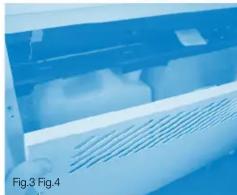
natural_image
Close-up of a white plastic electronic device with ventilation slots, no visible text or symbols
natural_image
Interior view of a laboratory or industrial facility with a white plastic container and adjacent storage unit (no visible text or symbols)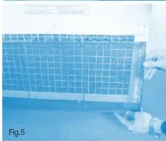
natural_image
Person holding a grid-patterned panel in a lab setting (no visible text or symbols)
natural_image
Person installing or adjusting a blue panel on a wall, no visible text or symbolsFig. 5 - The filter is located on the rear of the unit, ensure it is kept clean.
Fig. 6 - And in the top of the hinged section, in front of the evaporator.

Fig.1
- Portable Air Conditioning
- Operating Instructions & Safety Guide
- ANDREWS
- AIR CONDITIONING
- General Safety
- Electrical Safety
- Electrical Supply
- Air Cooled Units
- Air Flow
- Siting of ET 15
- Exhaust Tubes Air Cooled Unit
- Operating Instructions - ET15
- Operation Instructions
- Routine Maintenance
- Accessing the Filter
Brand : Andrews
Model : ET15
Category : Air conditioner