
APM101MK2 - Microphone Audac - Free user manual and instructions
Find the device manual for free APM101MK2 Audac in PDF.


| Product Type | Digital Paging Microphone |
| Model | APM101MK2 |
| Microphone Type | Back Electret Condenser |
| Polar Pattern | Uni-directional (Cardioid) |
| Frequency Response | 100 Hz - 20 kHz |
| Sensitivity | -42 dBV ± 3 dBV / Pa |
| Power Supply | 24 V DC |
| Power Consumption | 4 W max |
| Data Protocol | RS-485 |
| Bus Cabling | UTP CAT6 |
| Dimensions (Base) | 120 x 192 x 50 mm |
| Microphone Length | 32 cm |
| Weight | 1.35 kg |
| Audio Memory | Yes, for chime signals |
| Compressor/Limiter | Yes, with Automatic Gain Control |
| Fault Indication | All LEDs flash on malfunction |
| Priority Levels | Configurable |
| Zone Selection | General announcement only (single push-to-talk) |
| LED Indicators | Enable (Orange), Good (Green), Peak (Red), Low (Red) |
| Material Base | Steel |
| Maximum Bus Length | 133 m without external power, 300 m with |
| Maximum Devices on Bus | 2 without external power, 9 with |
Frequently Asked Questions - APM101MK2 Audac
User questions about APM101MK2 Audac
0 question about this device. Answer the ones you know or ask your own.
Ask a new question about this device
Download the instructions for your Microphone in PDF format for free! Find your manual APM101MK2 - Audac and take your electronic device back in hand. On this page are published all the documents necessary for the use of your device. APM101MK2 by Audac.
USER MANUAL APM101MK2 Audac
Chapter 1: Overview different APM models 7
Button functions 12
Overview ARU models 15
Chapter 2: Using the APM 16
Chapter 3: Connecting the APM 18
APM Connection summary 19
APM Connection example 21
RJ45 Pin connections 23
Chapter 4: Configuring the APM 24
Jumper settings 24
APM Test mode 27
Chapter 5: Technical specifications 29
4 AUDAC
Introduction
Digital Paging Microphone
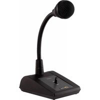
The APM1xx series are Digital Paging microphones with zone-selection buttons which are equipped with a digital audio memory which allowing storage of additional “chime” signals.
The gooseneck microphone is equipped with an electret capsule with cardioid pickup pattern. A built-in Compressor/Limiter with Automatic Gain Control controls the output level of the unit. There's also an indication on the front plate, to give the person who's talking an impression of his voice level.
The complete operation, from microphone cell till signal output including all digital parts, is guarded. In case of malfunction, there is a fault—indication. This is to make sure that when there is an emergency call, the message arrives at the listeners.
When there are several paging units placed in a bus-structure, you can configure them with different priority levels. The status of the audio-bus is indicated on the front panel (enable led).
The APM Paging range consists of four different models:
APM 101: Paging Unit just for General announcements.
APM 104: Paging Unit with 4 Zone Buttons, "Select All"—, "Clear"— and "Talk"—button.
APM 108: Paging Unit with 8 Zone Buttons, "Select All"—, "Clear"— and "Talk"—button.
APM 116: Paging Unit with 16 Zone Buttons, "Select All"—, "Clear"— and "Talk"—button.
The lower function buttons are standard programmed with following functions: a “Select All” button to activate all Paging Zones, a “Clear” button to deactivate all Paging Zones. The remaining buttons are used for Zone–Selection or other switch–functions.
All the buttons are freely programmable.
Chapter 1
Overview different APM models
The APM Product range consists of 4 standard models:
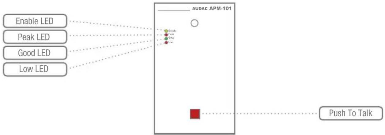
APM101: Contains 1 single button: Push to Talk (General announcement).
flowchart
graph TD
    A["Enable LED"] --> D["Sensor"]
    B["Peak LED"] --> D
    C["Good LED"] --> D
    E["Low LED"] --> D
    D --> F["AUDAC APM-101"]
    F --> G["Push To Talk"]
    style F fill:#f9f,stroke:#333,stroke-width:2px
APM104: Contains 4 programmable buttons on and a row with basic functions. Following functions are standard on these buttons:
Zone 1 – 4, Select All, Clear All, Push to Talk

flowchart
graph TD
    A["Enable LED"] --> B["AUDAC APM-104"]
    C["Peak LED"] --> B
    D["Good LED"] --> B
    E["Low LED"] --> B
    F["Select All"] --> B
    G["Clear All"] --> B
    H["End"] --> B
    I["Enable"] --> B
    J["Peak"] --> B
    K["Good"] --> B
    L["Low"] --> B
    M["Start"] --> N["4 Zone Buttons Push to Select / Deselect Zone"]
    O["Start"] --> P["Push To Talk"]
APM108: Contains a 4x2 programmable button matrix and a row with basic functions. Following functions are standard on these buttons:
Zone 1 – 8, Select All, Clear All, Push to Talk

flowchart
graph TD
    A["Enable LED"] --> B["Select All"]
    C["Peak LED"] --> D["Select All"]
    E["Good LED"] --> F["Select All"]
    G["Low LED"] --> H["Select All"]
    I["Select All"] --> J["Clear All"]
    K["AUDAC APM-108"] --> L["8 Zone Buttons Push to Select / Deselect Zone"]
    K --> M["Push To Talk"]
    L --> N["Green Square"]
    L --> O["Green Square"]
    L --> P["Red Square"]
    N --> Q["White Circle"]
    O --> R["White Circle"]
    P --> S["White Circle"]
APM116: Contains a 4x4 programmable button matrix and a row with basic functions. Following functions are standard on these buttons:
Zone 1 – 16, Select All, Clear All, Push to Talk

flowchart
graph TD
    A["Enable LED"] --> B["Select All"]
    C["Peak LED"] --> B
    D["Good LED"] --> B
    E["Low LED"] --> B
    F["Select All"] --> G["Clear All"]
    H["AUDAC APM-116"] --> I["16 Zone Buttons Push to Select / Deselect Zone"]
    H --> J["Push To Talk"]
    I --> K["Green Square"]
    I --> L["Green Square"]
    I --> M["Red Square"]
    K --> N["White Square"]
    L --> O["White Square"]
    M --> P["White Square"]
    N --> Q["White Square"]
    O --> R["White Square"]
    P --> S["White Square"]
    Q --> T["White Square"]
    R --> U["White Square"]
    S --> V["White Square"]
    T --> W["White Square"]
    U --> X["White Square"]
    V --> Y["White Square"]
    W --> Z["White Square"]
    X --> AA["White Square"]
    Y --> AB["White Square"]
    Z --> AC["White Square"]
    AA --> AD["White Square"]
    AB --> AE["White Square"]
Besides the programmable function buttons are 4 indication LED's provided on every APM Paging Microphone.
Orange LED (Enable): Bus Status (enable) Flashes when the chime is played illuminated when paging is busy
Green LED (Good): Voice level indication while speaking. When the green LED is illuminated, this means voice level is OK
RED LED's (Peak & Low): These LED's illuminate when the voice level is too low or too high

When enabled, the microphone will test the correct functioning. In case of malfunction (e.g. Microphone is broken), all LED's will start flashing. This way you can always monitor the proper functioning of
the APM Paging Microphone.
Button functions
Standard buttons:
Talk: By pressing this button, the “chime” starts to play. After this, you can make an announcement through the microphone.
Select All: By pressing this button, all "Zone" buttons will be selected at once.
Clear: This button deselects all selected "Zone" buttons.
Freely programmable buttons:
Zone-select: Press one time to select a Paging Zone. Pressing a second time will deselect the Zone. By pressing “Talk”, the message will be announced in the selected zones.
Play message: by pressing the button, a message is played in the selected zones.
Power Up delay: This is a function for switching on/off several devices. The step–time is adjustable on the receive/switch unit with a small trimmer.
Pulse Relay: By pressing a button, this function will activate a relay. This relay stays activated as long as you keep the button pressed down (Press and hold function) (e.g. To open a door with electrical door contact).
Toggle Relay: By pressing a button, this function will activate a relay. By pressing the button again, Toggle relay will deactivate the relay (Set–Reset function) (e.g. Switching lights,...).
Select Layer 0: Using layers (max. 3 layers) makes it possible to expand the Paging Unit. By pressing this button, Layer 0 will be activated.
Select Layer 1: Press this button to activate layer 1.
Select Layer 2: Press this button to activate layer 2.
Service mode:
The following button functions are available in "Service mode".
Volume Up (mic. or chime): With this function button, you can increase the volume (microphone or chime) with steps of 3dB.
Volume Down (mic. or chime): With this function button, you can decrease the volume (microphone or chime) with steps of 3dB.
Select mic.: By pressing this button, you select the microphone to change its volume.
Select chime: By pressing this button, you select the gong to change its volume.
Overview ARU models
The APM paging system can be applied to an existing audio system by means of the ARU Digital Relay Units. The ARU Digital Relay Units are switching boxes with an RS485 interface connection, which can be used to switch the audio signals coming from the APM paging microphones, or can be used as extension for your Digital Audio Matrix system with Digital APM paging microphones. This way its possible to control all different kinds of devices by means of the push buttons on your APM console. For example the control of lighting, curtains, beamer, ...
The ARU units can switch between two different signals and are available in three different versions with 4/8/16 relays.
ARU 104: Digital Relay Unit with 4 Relays
ARU 108: Digital Relay Unit with 8 Relays
ARU 116: Digital Relay Unit with 16 Relays
Chapter 2 Using the APM
When the APM system is switched on (turns automatically on when the power is connected), the paging console is automatically switched to its “User Mode”. In this mode, the function buttons have their standard functionality: Zone buttons (4–8–16 zones), one “Select All” button, one “Clear All” button, and one “Push to Talk” button. (except APM101, which has only “Push to Talk”)
When selecting a zone, the particular button for that zone will illuminate Orange. When pressing this button again, the Orange LED will stop illuminating. You can select all zones in one time by pressing the “Select All” button, and can be deselected by pressing “Clear All”.
To make announcements, the “Push to Talk” button should be pressed and kept pressed down while talking. This can only be done when the audio bus is not occupied (= not in use by another paging station, which means the Yellow LED is not illuminated).
Following actions will take place when an announcement will be made:
1) All selected zones will be transmitted to the Matrix system (R2) or Relay units (ARU), and the selected zones will be activated.
2) The chime tone will be played. During this step, the Orange "Enable" LED will flash.
3) When the chime tone is finished, the Orange “Enable” LED will stop flashing, the “Low” LED will illuminate and the microphone will be switched ON. From this moment, the announcement can begin. The best way to make an announcement is to speak through the microphone from a distance of ± 5 cm, with a voice level which makes the Green LED (Level = GOOD) illuminate.
4) To terminate the announcement, just release the "Push to Talk" button.
5) From this moment, you can change the selected zones for the next announcement.
The APM101 has just one “Push to Talk” button, which can be used to make general announcements (To all zones). It’s also possible make a specific configuration of the zones which have to be announced.
Chapter 3
Connecting the APM
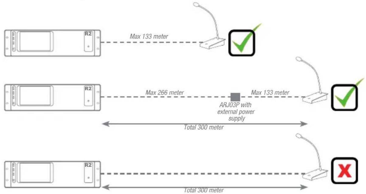
The APM's should be connected to the Matrix system or Relay units by means of Twisted pair CAT6 cabling. The maximum distance from the beginning of the bus to the last device is limited to a total cable length of 300 meters.
The supply voltage will be delivered to the APM over the twisted pair cable, and the voltage level on the APM side should be at least 16 Volts. When the voltage level on the APM side is lower than 16 Volts, the system won't work properly, and an ARJ03P junction box with external power supply need to be applied.
- Up to 9 APM units can be placed on the same bus, with a total maximum bus cable length of 300 meter using ARJ03P modules. (This 300 meters includes the cable distances from the ARJ03P junction boxes to the APM's)
– A maximum of two APM units can be placed on one APM bus, without external power supply - When using more than two APM units on one APM bus, an external power supply should be applied.
APM Connection summary
Maximum bus length
- Without an external power supply (without ARJ03P and external power supply) the maximum bus length for the APM bus is limited to 133 meter. (Only when APM is connected to the bus. When two APM's are connected, the maximum bus length is reduced to half)
- When using an external power supply (24 volts) within the 133 meter range to the APM, the maximum bus length is limited to 300 meter.
- The maximum distance from the ARJ03P junction box to the APM is limited to 3 meter and should be included within the 300 meter maximum total bus length.
Maximum bus devices
- Without an external power supply (without ARJ03P and external power supply) the maximum devices on the APM bus is limited to two.
- With external power supply (24 Volts) the maximum devices on the APM bus is limited to 9.
Power supply calculation
The power for the APM devices will be delivered from the receiver end (from the Digital Matrix System or from the ARU Digital Relay Unit) over the CAT6 cabling to the APM device. If the total cable length is over 133 meters, the voltage on the APM side will become insufficient. In this case, an ARJ03P junction box with external power supply should be applied to deliver the desired voltage to the APM. The maximum current which can be transferred over a CAT6 cable is 0.6 Ampere. Depending of the devices connected to the bus, the ARJ03P junction boxes should be placed in a way, the current transferred over the CAT6 cable never comes above 0.6 Amps.
The tables on page 22 shows the maximum current ratings for the devices which can be connected to the APM bus, and shows you the maximum cable length related to the quantity of deviced connectes to the bus.
A simplified calculation method can be used to calculate the maximum cable length, related to the quantity of device connected to on the bus: L = 133 / x, where x stands for the number of connected devices.
For example: When 6 devices are connected to one power supply, the maximum cable length of the databus is L = 133 / 6 = 22 meters.
APM Connection examples
Connection examples with ONE APM device on one bus
Connection examples with MULTIPLE APM devices on one bus

flowchart
graph LR
    A["Device R2"] -->|Total bus length Max 300 meter| B["ARJ03P"]
    B --> C["Bus Terminated"]
    C --> D["Max 3 meter"]
    D --> E["Maximum up to 9 devices on one APM bus"]
    style A fill:#f9f,stroke:#333
    style B fill:#ccf,stroke:#333
    style C fill:#cfc,stroke:#333
    style D fill:#fcc,stroke:#333
    style E fill:#ffc,stroke:#333
Maximum Current Ratings
| Device Current rating | |
| APM101 / 104 / 108 / 116 | 0.3 A |
| ARU104 0.2 A | |
| ARU108 0.3 A | |
| ARU116 0.4 A | |
Maximum Cable length related to the number of APM devices connected to the bus
| Number of APM devices | Maximum Cable length |
| 1 133 meter | |
| 2 66 meter | |
| 3 44 meter | |
| 4 33 meter | |
| 5 26 meter |
RJ45 Pin connections
PINOUT (RS485, Analogue / Digital Audio, +24V DC):
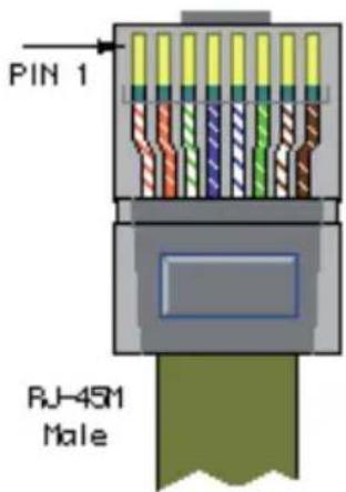
Pin 1 White-Orange Not connected
Pin 2 Orange Not connected
Pin 3 White-Green +24V DC
Pin 4 Blue RS485 A
Pin 5 White-Blue RS485 B
Pin 6 Green GND
Pin 7 White-Brown AUDIO TX A / S+
Pin 8 Brown AUDIO TX B / S-
Chapter 4 Configuring the APM Jumper settings
Analogue / Digital Paging selection:
The APM's are standard delivered with the configuration to be

used in combination with ARU relay units, with the audio signal set to analogue. When the APM's should be used in combination with Digital Matrix Systems, the configuration should be changed to
Bus Termination:
The APM's are standard delivered to be used with only one APM

natural_image
Simple line drawing of a pair of eyeglasses (no text or symbols)on one databus (on one PI port). When multiple APM should be used on one bus, the bus termination settings need to be changed.
1) Only one APM on one databus
When only one APM is used on the databus, the databus needs to be terminated by the termination jumper J5 which is placed inside the APM. This jumper is placed in it's standard configuration, so no changes need to be made when using only one APM on a databus.
2) Multiple APM's on one databus
When multiple APM's are used on one databus, the termination jumpers J5 inside the APM's should be removed. The bus should be terminated by means of the termination jumpers on the last ARJ03P junction box in the bus structure. Both the audio and communication lines need to be terminated by means of the jumpers.
Analogue / Digital Paging Selection
| Digital Paging(Matrix System) | Analogue Paging(ARU Relay Unit) | |
| J1 | Placed Open | |
| J2 | Placed Open | |
| J3 | Open Placed | (Standard) |
| J4 | Open Placed | (Standard) |
Bus Termination
| One APM Multiple APM's | ||
| J5(APM) | Placed (Standard) Open | |
| Audio(ARJ03P) | n/a | Position 1(Only last one in Chain) |
| Com(ARJ03P) | n/a | Position 1(Only last one in Chain) |


INDEX

Jumper Placed

Jumper not Placed
APM Test mode
In test mode, the Chime and Microphone of the APM can be tested and the volume for can be adjusted.
The test mode can be entered by holding the PTT (Push To Talk) button when powering up (connecting the RJ45 connector). After the Test mode is entered, the “PTT” button will illuminate Orange while the “Select All”, the “Deselect All”, the “Chime” and the “Mic” buttons will illuminate green.
After pressing the “Chime” button, the volume for the Chime can be increased and decreased by pushing the “+” and “−” buttons. To test if the selected volume is correct, you can press the orange “Test” button, whereafter the chime tone will be heard.

The volume for the Microphone can be adjusted by pressing the “Mic” button and pressing the “+” and “−” buttons for increasing or decreasing the volume. To test if the deleted volume is correct, you can press the orange “Test” button, whereafter the voice speaking into the microphone will be heard.
After the volume settings for both Chime and Microphone are made correctly, you can return back to the regular operation mode by pushing both “EXIT” (The “Select All” and “Deselect All”) buttons at the same time.
Chapter 5
Technical Specifications
Microphone Type: Back Electret Condenser
Polar pattern: Uni-directional
Frequency response: 100 Hz - 20 kHz
Sensitivity: -42 dBV ± 3dBV / Pa
Power supply 24 V DC
Max Power Consumption 4 Watt
Data Protocol RS-485
Bus cabling UTP CAT6
Dimensions base 120 x 192 x 50 mm
Material base Steel
Length Microphone 32 cm
Weight ± 1.35 Kg


- AUDAC
- Introduction
- Digital Paging Microphone
- Chapter 1
- Overview different APM models
- Button functions
- Standard buttons:
- Freely programmable buttons:
- Service mode:
- Overview ARU models
- Chapter 2 Using the APM
- Chapter 3
- Connecting the APM
- APM Connection summary
- Maximum bus length
- Maximum bus devices
- Power supply calculation
- APM Connection examples
- RJ45 Pin connections
- Chapter 4 Configuring the APM Jumper settings
- Analogue / Digital Paging selection:
- Bus Termination:
- 1) Only one APM on one databus
- 2) Multiple APM's on one databus
- APM Test mode
- Chapter 5
- Technical Specifications
Brand : Audac
Model : APM101MK2
Category : Microphone