
MPX48 - Microphone Audac - Free user manual and instructions
Find the device manual for free MPX48 Audac in PDF.


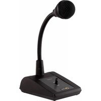
| Product Type | Dynamic Microphone |
| Brand | Audac |
| Model | MPX48 |
| Directional Pattern | Cardioid |
| Frequency Response | 50 Hz - 15 kHz |
| Impedance | 600 ohms |
| Sensitivity | -54 dBV/Pa |
| Connector | XLR 3-pin |
| Power Requirement | None (dynamic) |
| Dimensions (Length) | 180 mm |
| Dimensions (Diameter) | 50 mm |
| Weight | 350 g |
| Main Features | High sound quality, feedback rejection, rugged build |
| Application | Vocal, speech, live performance |
| Cleaning | Wipe with dry cloth |
| Safety | Avoid moisture and shock |
| Spare Parts | Replacement grille available |
| Repairability | Replaceable capsule and cable |
| Operating Temperature | -10°C to 50°C |
| Warranty | 2 years (check local) |
Frequently Asked Questions - MPX48 Audac
User questions about MPX48 Audac
0 question about this device. Answer the ones you know or ask your own.
Ask a new question about this device
Download the instructions for your Microphone in PDF format for free! Find your manual MPX48 - Audac and take your electronic device back in hand. On this page are published all the documents necessary for the use of your device. MPX48 by Audac.
USER MANUAL MPX48 Audac
Safety requirements 6
Caution servicing 7
EC Declaration of Conformity 7
Waste of Electrical and Electronic Equipment (WEEE) 7
Chapter 1: Connections and connectors 8
Connection standards 8
Chapter 2: Overview MPX
Chapter 3: Connecting & Configuring the MPX 12
Connecting the MPX 12
Configuring the MPX 1:
Chapter 4: Technical specifications 14
Introduction
Paging microphone for MTX
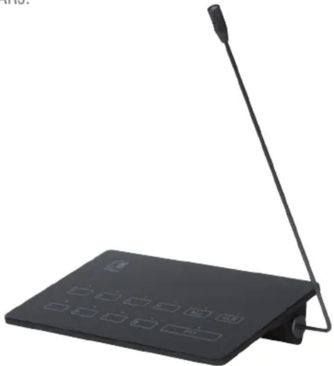
The MPX microphones are specifically designed to be used in combination with the MTX Multi-Zone audio matrix system. They come in two different versions with four and eight zone selection buttons, offering a plug-and play solution for corresponding MTX matrix systems.
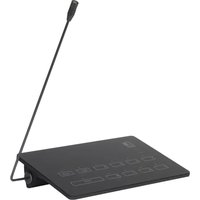
The construction is made of weighted ABS material and finished with an acrylic top panel. The buttons are integrated using the capacitive touch principle without any mechanically moving parts. Selection & status LED's are integrated below the acrylic surface, giving an indication of the selected zones and databus status. Besides the zone selectors, quick operation is allowed through the Select & Clear all buttons, while the push-to-talk (PTT) button should be pressed during the announcement.
An integrated chime tone is heard before any announcement. Announcements can be made to the integrated pipe—neck microphone with a cardioid pickup pattern which can be tilted to the desired angle.
The microphone should be connected to the matrix system using the fixed cable with a length of 2 meters. The distance can be extended to a maximum length of 300 meters, using standard CAT5E (or better) twisted pair cabling. Cascading of multiple paging stations is made possible using the priority-based (user-configurable) databus, when using additional junction boxes ARJ03P or CP45ARJ.
natural_image
Black electronic device with antenna and control panel (no visible text or symbols)Precautions
READ FOLLOWING INSTRUCTIONS FOR YOUR OWN SAFETY
- ALWAYS KEEP THESE INSTRUCTIONS FOR FUTURE REFERENCE. NEVER THROW THEM AWAY
• ALWAYS HANDLE THIS UNIT WITH CARE
• CLEAN ONLY WITH DRY CLOTH
• HEED ALL WARNINGS AND FOLLOW ALL INSTRUCTIONS - NEVER EXPOSE THIS EQUIPMENT TO RAIN, MOISTURE, ANY DRIPPING OR SPLASHING LIQUID. NEVER PLACE AN OBJECT FILLED WITH LIQUID ON TOP OF THIS DEVICE
- DO NOT INSTALL THIS UNIT NEAR ANY HEAT SOURCES SUCH AS RADIATORS OR OTHER APPARATUS THAT PRODUCE HEAT
- DO NOT PLACE THIS UNIT IN ENVIRONMENTS WITH A HIGH LEVEL OF DUST, HEAT, MOISTURE OR VIBRATION
• THIS UNIT IS DEVELOPED FOR INDOOR USE ONLY. DO NOT USE IT OUTDOORS - PLACE THE UNIT ON A STABLE BASE OR MOUNT IT IN A STABLE RACK
- ONLY USE ATTACHMENTS & ACCESSORIES SPECIFIED BY THE MANUFACTURER.
- UNPLUG THIS APPARATUS DURING LIGHTNING STORMS OR WHEN UNUSED FOR LONG PERIODS OF TIME
- CAREFULLY CHECK THE UNIT'S CONDITION AFTER UNPACKING. IF THERE IS ANY DAMAGE TO THE CARTON BOX OR THE UNIT ITSELF, INFORM YOUR VENDOR IMMEDIATELY.
- THE INSTALLATION, CONNECTION AND CONFIGURATION OF THE DEVICE SHOULD BE DONE BY QUALIFIED TECHNICIANS
- USE CABLES WITH CLEAR COLOUR CODING INDICATING THE POLARITY AND MAINTAIN THE SAME POLARITY THROUGHOUT THE WHOLE SYSTEM.

CAUTION – SERVICING
This product contains no user serviceable parts. Refer all servicing to qualified service personnel. Do not perform any servicing (unless you are qualified to do so.)
EC DECLARATION OF CONFORMITY
This product conforms to all the essential requirements and further relevant specifications described in following directives: 2004/108/EC (EMC) and 2006/95/EC (LVD)
WASTE ELECTRICAL AND ELECTRONIC EQUIPMENT (WEEE)
The WEEE marking indicates that this product should not be disposed with regular household waste at the end of its product life. This regulation is created to protect both the environment and human health.
This product is developed and manufactured with high quality materials and components which can be recycled and/or reused. Please dispose of this product at your local collection point or recycling centre for electrical and electronic waste. Do this to make sure that the product is recycled in an environmental friendly way, and will help to protect the environment in which we all live.
Chapter 1
Connections and connectors
CONNECTION STANDARDS
The in- and output connections for AUDAC audio equipment are performed corresponding to international wiring standards for professional audio equipment.
RJ45 (RS485, Audio, +24V DC):
For connection to MTX Matrix
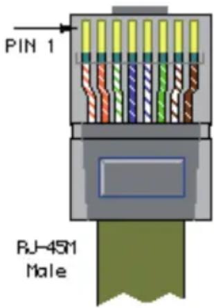
Pin 1 White-Orange Not connected
Pin 2 Orange Not connected
Pin 3 White-Green +24V DC
Pin 4 Blue RS485 A
Pin 5 White-Blue RS485 B
Pin 6 Green GND
Pin 7 White-Brown AUDIO MIC +
Pin 8 Brown AUDIO MIC –
The microphone should be connected to the matrix system using the fixed connection cable with a length of 2 meters. The distance can be extended to a maximum length of 300 meters, using CAT5E (or better) twisted pair cabling.
Cascading of multiple paging stations is possible by connecting them in parallel using the priority-based (user-configurable) databus.

natural_image
Simple line drawing of a pair of eyeglasses (no text or symbols)ATTENTION
The twisted pair cabling must always be ‘straight’. In case of self made cabling, it must be wired as described above, to make the system work properly.
Chapter 2
Overview MPX
natural_image
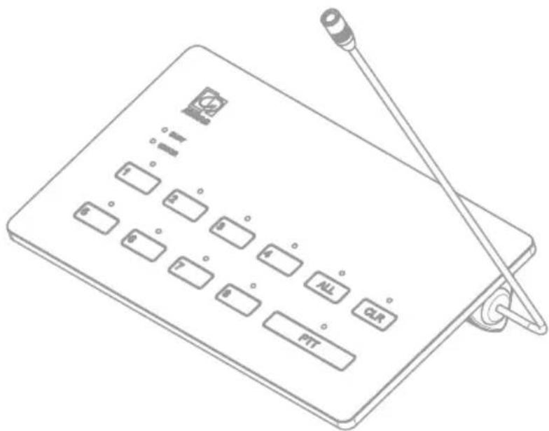
Line drawing of a portable electronic device with labeled buttons and a antenna (no text or symbols beyond basic labels)The front panel of the MPX contains various selectors and indicators. All selection buttons are implemented using capacitive touch principle, whereby selection is done by gliding your finger over it.
A zone selection button with indicator LED on top of it is provided for every zone (4 zones for MPX48 & 8 zones for MPX88). The indicator LED will illuminate when the corresponding zone is selected. Using the 'ALL' (Select all) and 'CLR' (Clear all) buttons, zones can be quickly selected & de-selected for increased user convenience.
The ‘PTT’ (Push-To-Talk) button should be pressed and held when making announcements. When releasing, announcements will be stopped. An integrated chime tone will be heard before any announcement is made.
A 'BUSY' and 'ERROR' monitoring LED indicate the current operation status of the device. The 'BUSY' LED will illuminate while the databus is occupied through another paging microphone or when the integrated chime is playing. When the 'PTT' button is pressed and the 'BUSY' LED is off, accouncements can be made.
The ‘ERROR’ LED will illuminate when no connection is established between the microphone and the matrix, or when no acknowledge to announcements is given by the matrix.
Chapter 3
Connecting & Configuring the MPX
Depending the number of connected MPX paging microphones to one matrix, the connection and configuration should be done in an appropriate way.
When only one MPX is connected to a system, it can simply be plugged and used without requiring any further configuration. When multiple MPX microphones are connected to a system, cascaded connections and priority configurations should be made as described in this chapter.
The maximum distance from the beginning of the databus to the last device is limited to a total cable length of 300 meters. The supply voltage for the MPX is delivered over the twisted pair cabling and the voltage level on the MPX side should be at least 15 Volts. When the voltage drop on the MPX side is lower than 15 Volts, the system won't work properly and an ARJ03P junction box with external power supply needs to be applied.
Connecting the MPX
1) Connecting one MPX
When only one paging microphone is required in your system, the MPX can be directly connected to the 'PAGING' RJ45 connector on the MTX as shown in below diagram.

2) Connecting multiple MPX
When multiple paging microphones are required in your system, cascading can be done by connecting them in parallel on the databus, and connecting it to the 'PAGING' RJ45 connector on the MTX as shown in below diagram.
The ARJ03P junction box can be used for easy connectivity of multiple paging consoles on one databus.

Configuring the MPX
1) Configuration of one MPX
When only one MPX is connected, no configuration is required. After connected the MPX to the matrix as shown above, the system is ready for operation.
2) Configuration of multiple MPX
When multiple MPX are connected, the paging is priority based and priority settings are needed to be made. An unique address should be assigned to every MPX, whereby the lowest address '001' will have the highest priority. When an announcement is being made, and another speaker with higher priority requests for an announcement, announcements with lower priority will be interrupted.
Priority settings should be made in the MTX web-based interface under 'Setup' > 'System Configuration' > 'Paging'. In this screen, the address for the corresponding microphone can be selected. After selected, the 'Set Address' button should be pressed and subsequently the PTT LED's on all MPX will start blinking. After pressing the PTT button, the address will be assigned to the corresponding MPX microphone.
Chapter 4
Technical specifications
| Microphone type | Back elektret condenser | ||
| Polar pattern | Cardioid | ||
| Frequency response | 50 Hz – 16 kHz | ||
| Sensitivity | 45 | dB | |
| Max. SPL | 130 | dB | |
| Power supply | 24 V DC (from MTX) | ||
| (15V Minimal operation limit) | |||
Power consumption 1.5 Watt
| Dimensions | 221,5 x 43 x 111,6 mm | |||
| Microphone | length | 250 | mm | |
| Weight | net | 0.33 | Kg | |
| Construction | ABS with acrylic top | |||
| Connection | RJ45 (Fixed 2 meter cable) | |||
| Bus cabling | UTP Cat5E (or better) | |||
| Control | databus | RS485 | ||
| Audio | databus | Differential | analogue | |
| Colour | Black | (RAL9004) | ||
Paging zones MPX48 4 Zones (use with MTX48) MPX88 8 Zones (use with MTX88)
Packaging Carton box
Accessories included Windscreen
Connection cable 2 meter
Shipping weight & volume 2 Kg - 0.0012 Cbm
Notes
Notes


- Chapter 1: Connections and connectors 8
- Chapter 2: Overview MPX
- Chapter 3: Connecting & Configuring the MPX 12
- Chapter 4: Technical specifications 14
- Introduction
- Paging microphone for MTX
- Precautions
- READ FOLLOWING INSTRUCTIONS FOR YOUR OWN SAFETY
- CAUTION – SERVICING
- EC DECLARATION OF CONFORMITY
- WASTE ELECTRICAL AND ELECTRONIC EQUIPMENT (WEEE)
- Chapter 1
- Connections and connectors
- CONNECTION STANDARDS
- RJ45 (RS485, Audio, +24V DC):
- ATTENTION
- Chapter 2
- Overview MPX
- Chapter 3
- Connecting & Configuring the MPX
- Connecting the MPX
- 1) Connecting one MPX
- 2) Connecting multiple MPX
- Configuring the MPX
- 1) Configuration of one MPX
- 2) Configuration of multiple MPX
- Chapter 4
- Technical specifications
- Notes
Brand : Audac
Model : MPX48
Category : Microphone