
POW2 - Microphone Audac - Free user manual and instructions
Find the device manual for free POW2 Audac in PDF.

| Product Type | 16-Channel Power Amplifier Kit (8 Stereo) |
| Amplifier Class | Class-D |
| Output Power per Channel | 60 W (8 channels) |
| Bridge Mode Output Power | 8 x 120 W |
| Protection Circuits | DC malfunction, short circuit, overheating, overload |
| Cooling System | Large heatsink with temperature-controlled speed ventilation fan |
| Input Signal Source | Internal DSP output (linked inside matrix) |
| Output Connectors | 4-pin Terminal block (8 connectors, 5.08 mm pitch) |
| Power Supply Unit | Switching power supply with PFC (included) |
| Mains Voltage | 110–240 V AC |
| Fuse Rating | 2 x T4AL/250V slow blow |
| Compatibility | Audac R2 and M2 matrix systems |
| Installation | Internal installation inside matrix housing (qualified technicians only) |
| Package Contents | Amplifier module, power supply, cables (8 speaker, 8 signal, 1 mute), power cable set, fuses, ferrite cores, 8 terminal block connectors, sticker |
| Additional Features | Mute (anti-plop) cable connection; speed-controlled fan starts only when temperature rises |
| Safety Notes | Installation by qualified technicians only; incorrect installation may cause permanent damage |
Frequently Asked Questions - POW2 Audac
User questions about POW2 Audac
0 question about this device. Answer the ones you know or ask your own.
Ask a new question about this device
Download the instructions for your Microphone in PDF format for free! Find your manual POW2 - Audac and take your electronic device back in hand. On this page are published all the documents necessary for the use of your device. POW2 by Audac.
USER MANUAL POW2 Audac
The POW2 is a sixteen channel power amplifier kit which is an optional device to be installed inside the R2 Multi-Zone Digital Audio Matrix and M2 Multi-Media Digital Audio Mixer devices.
In their standard configuration, these matrix systems are equipped with 8 line level output channels where to the appropriate amplifiers for your application can be connected.
In combination with the POW2 Power amplifier kit, they can be turned into a powered matrix system, delivering an amplified output signal in the same single housing. This can be very useful for applications where no large power capacities are required and the available rackspace is limited.
The POW2 consists of a 16 Channel (8 Stereo Channel) Class-D amplifier, delivering a power of 60 Watt to every channel. In bridge mode an output power of 8 x 120 Watt can be obtained.
The input signal is internal linked from the DSP output and the output connections are provided on the rear panel of the matrix system and are performed by using 4-pin Terminal block connectors allowing connections for separate or bridged output channels.
It features an advanced protection circuit which protects against DC malfunctioning, short circuit, overheating and overload while a large heatsink and speed controlled ventilation fan ensure a proper operation temperature is continuously maintained.
The POW2 Power amplifier kit includes the power amplifier module, a switching power supply and all necessary connection and installation accessories to properly install the kit inside the Matrix's housing.
Installation precautions!

The installation of the Power Amplifier Kit unit may only be performed by qualified technicians.
Incorrect installation can lead to permanent damage or incorrect functioning of the equipment.
Package contents
– Power amplifier module
– Power supply unit with PFC
– Loudspeaker output cables 200 mm (8 pcs)
– Stereo shielded signal cable 420 mm (2 pcs)
– Stereo shielded signal cable 460 mm (2 pcs)
– Stereo shielded signal cable 500 mm (2 pcs)
– Stereo shielded signal cable 540 mm (2 pcs)
- Mute cable 400 mm
- Power cable set Red / Black / Yellow
- 2 x T4AL/250V Slow blow fuse
- 2 Large Ferrite core for SD/MMC connection flatcable (one might be mounted on the Power supply already)
- 8 x 4-Pin Terminal block output connectors (5.08 mm)
- POW 2 Option Sticker
Installing
Mounting and connecting
Please note this manual is for both M2 and R2 Assembly.
Picture used in this documentation are for M2 and may differ from R2.
Step 1:
Make sure the Matrix system is powered off and the power inlet is disconnected from the mains power.
Step 2:
Open the device housing by carefully removing the screws from the top panel of the device.
Step 3:
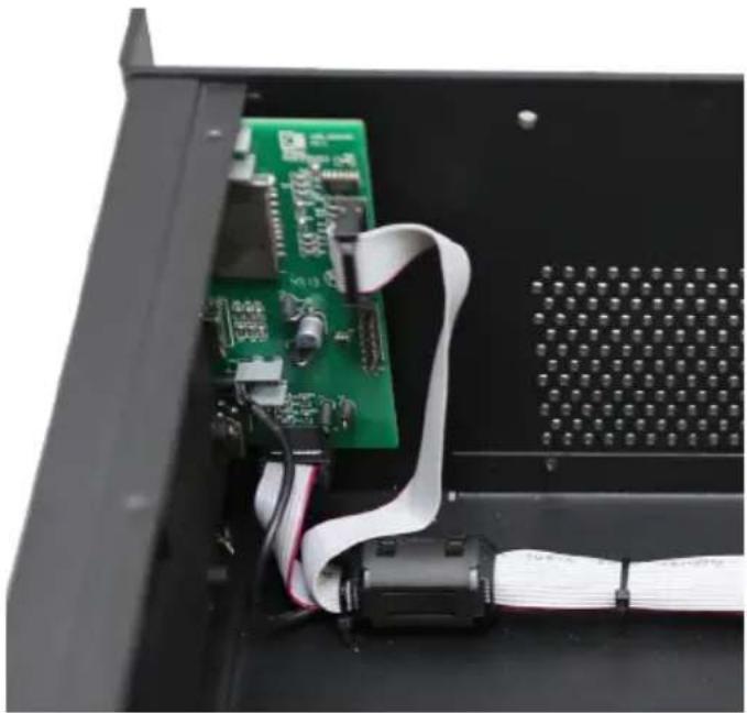
For M2: Place one of the supplied ferrite cores around the flatcables coming from the USB and SD/MMC board on the front panel of the device.
natural_image
Close-up of an open electronic device showing a green circuit board and white cable, no visible text or symbolsStep 4:
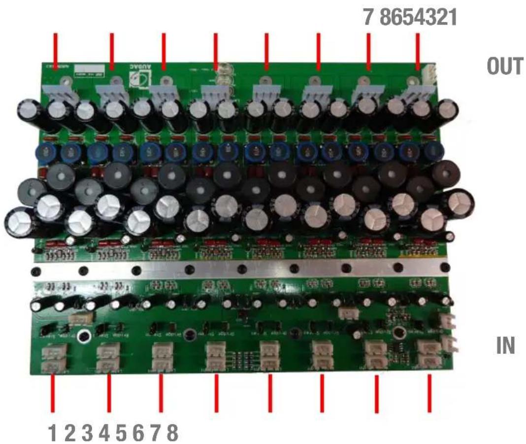
Amplifier channel layout
Attach the 8 loudspeaker output cables to the I/O board(s) of the system.
Depending of the kind of system (R2 or M2) the output board will be different. The loudspeaker output cables should be connected to the large 4-pin connectors on the bottom side of the I/O board(s).
natural_image
Interior view of an electronic device showing multiple connected modules with visible wiring and connectors (no text or symbols)Step 5:
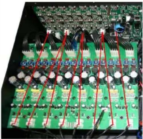
Attach the 8 stereo shielded signal cables to the amplifier module. Mark the cables to keep a clear overview of which cable is connected to which channel. The corresponding cable length for each channel is described in the table below:
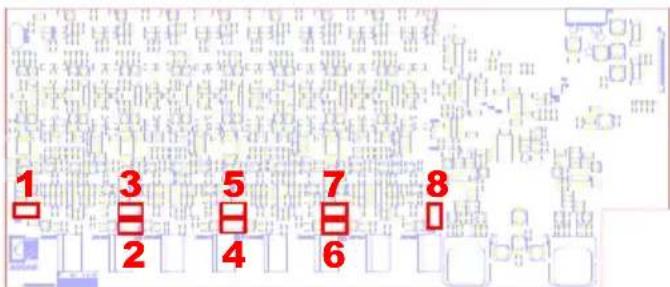
Cable lengths: 420 mm: Channels 4 & 5 500 mm: Channels 2 & 7 460 mm: Channels 3 & 6 540 mm: Channels 1 & 8
R2 10 board signal connections
natural_image
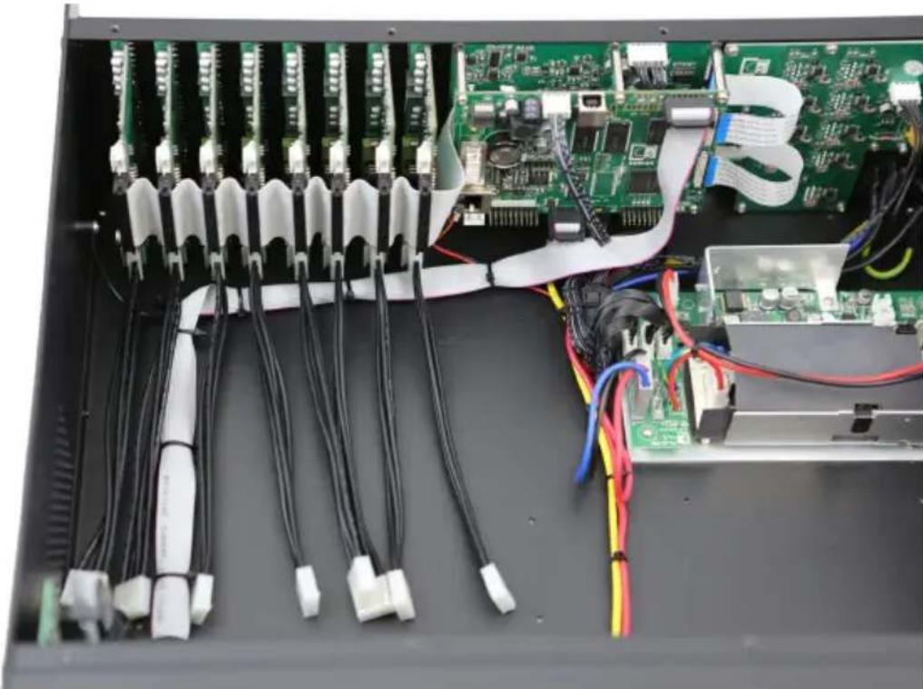
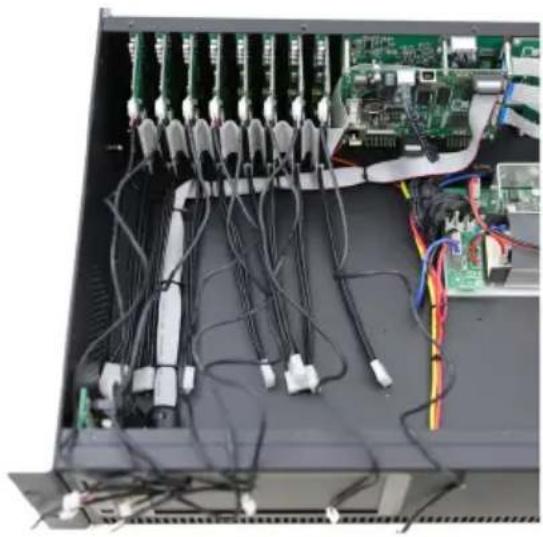
Interior view of an electronic equipment rack with multiple cables and connectors (no visible text or labels)Align the cables to facilitate the placing of the amplifier module.
Use cable ties to hold the signal cables together.
Signal cables will go under the amplifier module whereas the output cables remain at the back of the unit.
Step 6:
Then place the amplifier inside the matrix housing and fix it by inserting and tightening four screws from the housings bottom side.
natural_image
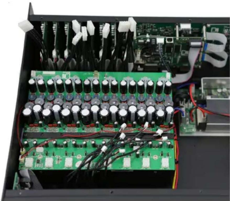
Interior view of an electronic circuit board with capacitors, resistors, and wiring (no visible text or symbols)Connect the loudspeaker cables coming from the I/O board to the provided connectors on the amplifier module. Make sure each connector on the I/O board is connected in sequential order to the corresponding connector on the amplifier module.
Connect the stereo shielded signal cables coming from the I/O board to the corresponding connectors on the amplifier module.
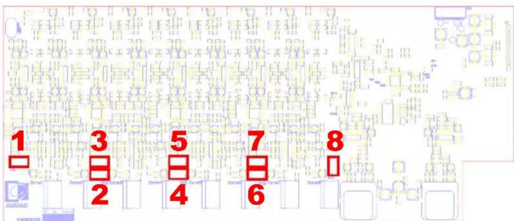
Make sure the right amplifier channel is connected to the corresponding connector on the I/O board. The connectors on the I/O board of the R2 are marked with the number of the corresponding channel.
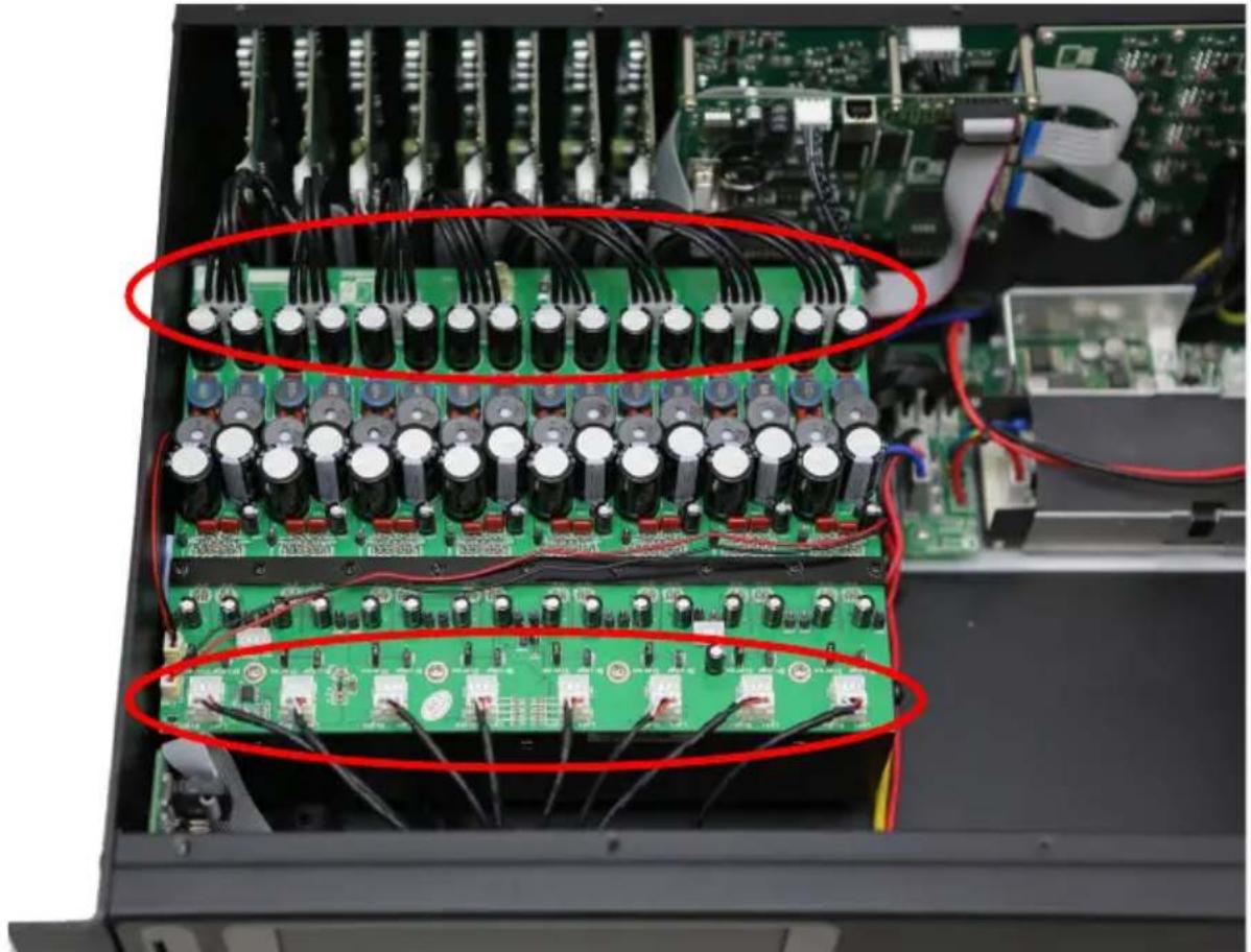
natural_image
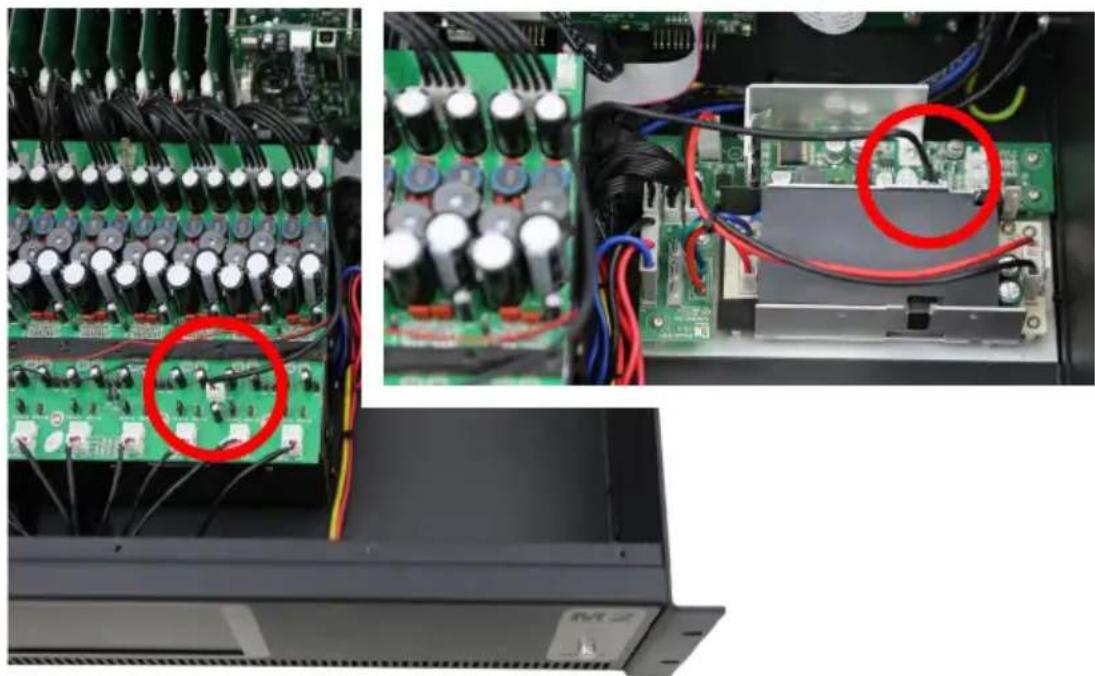
Interior view of an electronic device showing a multi-tiered circuit board with capacitors and connectors, no visible text or symbols.Note: Remember for R2 the I/O board is different, so please make sure you connect the right channels to each other:
natural_image
Close-up of a green printed circuit board with multiple electronic components and red wiring (no visible text or symbols)Step 8:
Connect the mute (Anti plop) cable to the provided connector on the amplifier module and the small power supply (PowerDSP).
natural_image
Interior view of an electronic device showing circuit board, capacitors, and wiring (no visible text or symbols)Step 9:
Power Supply unit
Please check if the suppression coil is attached to the power cable. If it isn't, please attach the supplied suppression coil first.
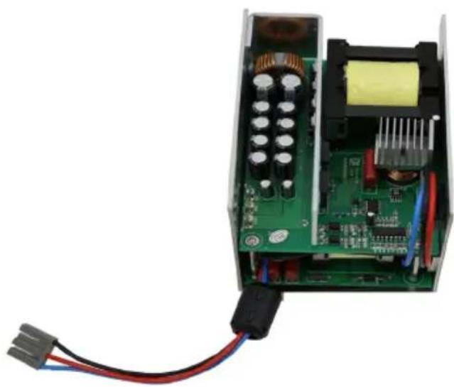
natural_image
Interior view of an electronic circuit board with visible components and wiring (no text or symbols)Place the power supply unit with PFC inside the matrix housing and fix it by inserting and tightening four screws from the housings bottom side.
natural_image
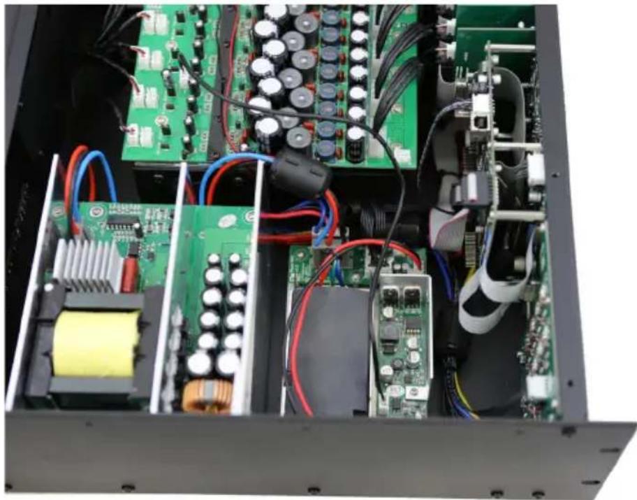
Interior view of an electronic device showing internal components like circuit boards, capacitors, and wiring (no visible text or labels)Step 10:
Connect the mains (110V AC \~ 240 V AC) cable from the big power supply (Power supply unit with PFC) to the provided connector on the small power supply (PowerDSP). Make sure the included ferrite core is placed around these cables.

natural_image
Interior view of an electronic device showing internal circuit boards, capacitors, and wiring (no visible text or labels)Step 11:
Connect the 28 Volts output (+28V, GND, -28V) of the big power supply to the amplifier module.
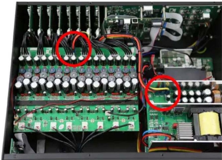
natural_image
Interior view of an electronic circuit board with capacitors, resistors, and wiring (no visible text or labels)Align the connected cables nicely and fasten them with Cable ties. Ensure the airflow of the fan is not blocked by cables.
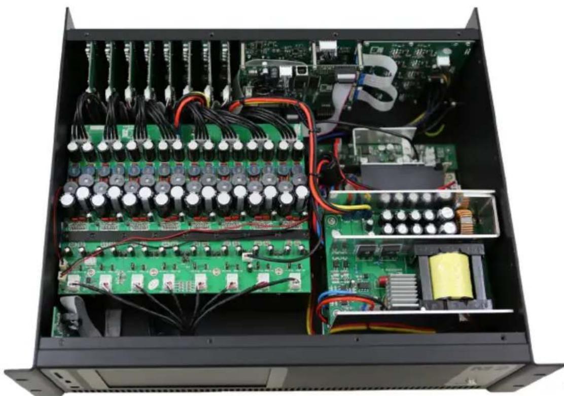
natural_image
Interior view of an electronic device showing internal circuit boards, capacitors, and wiring (no visible text or labels)Step 12:
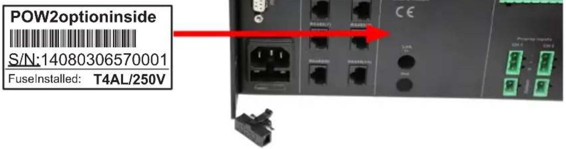
The last step before powering the M2/R2 is to remove the fuse holder on the bottom left side at the back of the device, replace both of the fuses (the active one and the spare one) by the T4AL/250V fuse and place the fuse holder back into the device.
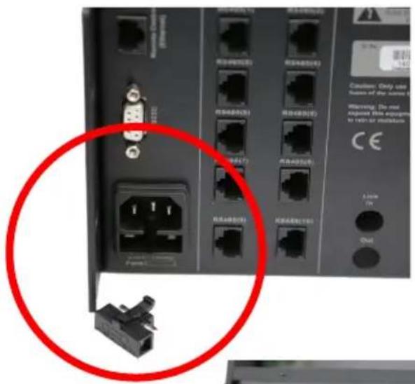
Finally, attach POW2 option sticker at the back of the device.
Ready:
The power amplifier kit is now fully installed and ready to be used. There is no need for any software adjustments to the matrix system.
Verify if all connections are done correctly and power on the Matrix system.
Test all the loudspeaker outputs separately with a loudspeaker to check if every channel is working correctly.
Keep the matrix system running for about 1 hour, and check if the cooling fan is working correctly. The cooling fan is temperature controlled which means that it won't rotate once the system is powered ON, but will start working once the temperature inside the device is increasing.


Brand : Audac
Model : POW2
Category : Microphone