CLM5000 - Cables for Computers and Peripherals Black Box - Free user manual and instructions
Find the device manual for free CLM5000 Black Box in PDF.


| Product Type | Computer Cable |
| Brand | Black Box |
| Model | CLM5000 |
| Category | Cables for Computers and Peripherals |
| Connector A | USB Type-A Male |
| Connector B | USB Type-B Male |
| Cable Length | 1.8 m (6 ft) |
| Shielding | Shielded with Foil and Braid |
| Data Transfer Rate | Up to 480 Mbps (USB 2.0) |
| Compatible Devices | Computers, Printers, Scanners, External Drives |
| Material | PVC Jacket, Bare Copper Conductors |
| Color | Black |
| Weight | 0.12 kg |
| Operating Temperature | 0°C to 60°C (32°F to 140°F) |
| Plug and Play | Yes |
| RoHS Compliant | Yes |
| Warranty | Limited Lifetime Warranty |
| Maintenance | Keep dry and away from heat sources |
| Safety | Use only with compatible devices to avoid damage |
| Spare Parts | Not applicable (integrated cable) |
Frequently Asked Questions - CLM5000 Black Box
User questions about CLM5000 Black Box
0 question about this device. Answer the ones you know or ask your own.
Ask a new question about this device
Download the instructions for your Cables for Computers and Peripherals in PDF format for free! Find your manual CLM5000 - Black Box and take your electronic device back in hand. On this page are published all the documents necessary for the use of your device. CLM5000 by Black Box.
USER MANUAL CLM5000 Black Box
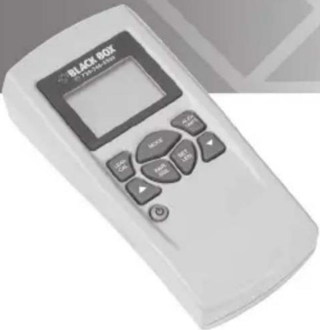
Use to measure cable length and generate tone on industrial, telco, and coax cable (not CATx).
Works on single- or two-conductor cables.
Compact, handheld unit.
Customer Support Information
Order toll-free in the U.S.: Call 877-877-BBOX (outside U.S. call 724-746-5500) • FREE technical support 24 hours a day, 7 days a week: Call 724-746-5500 or fax 724-746-0746 • Mailing address: Black Box Corporation, 1000 Park Drive, Lawrence, PA 15055-1018 • Web site: www.blackbox.com • E-mail: info@blackbox.com
FEDERAL COMMUNICATIONS COMMISSION AND INDUSTRY CANADA
RADIO FREQUENCY INTERFERENCE STATEMENTS
This equipment generates, uses, and can radiate radio-frequency energy, and if not installed and used properly, that is, in strict accordance with the manufacturer's instructions, may cause interference to radio communication. It has been tested and found to comply with the limits for a Class A computing device in accordance with the specifications in Subpart B of Part 15 of FCC rules, which are designed to provide reasonable protection against such interference when the equipment is operated in a commercial environment. Operation of this equipment in a residential area is likely to cause interference, in which case the user at his own expense will be required to take whatever measures may be necessary to correct the interference.
Changes or modifications not expressly approved by the party responsible for compliance could void the user's authority to operate the equipment.
This digital apparatus does not exceed the Class A limits for radio noise emission from digital apparatus set out in the Radio Interference Regulation of Industry Canada.
WEEE Directive Compliance (RoHS)
This product complies with the Waste Electrical and Electronic Equipment (WEEE) Directive, 2 002 /96/EC. It should not be disposed of as unsorted municipal waste and should be collected separately and disposed of according to your national regulations.
Normas Oficiales Mexicanas (NOM) Electrical Safety Statement
Trademarks Used in This Manual
Black Box and the Double Diamond logo are registered trademarks of BB Technologies, Inc.
Any other trademarks mentioned in this manual are acknowledged to be the property of the trademark owners.
Chapter Page
- Specifications....6
- Overview 8
2.1 Introduction......8
2.2 Features....8
2.3 What's Included 9
2.4 Hardware Description ......9
- General Functions....10
3.1 PWR Key and Auto Power Off 10
3.2 Mode Key 10
3.3 AL/CU Units Key 10
3.4 LCD Display Icons 11
- Using the Cable Length Meter 12
4.1 AWG Mode 12
4.2 Pair SGL Key 14
4.3 Coax, Network, and Telco Modes....16
4.4 Tone Mode....18
4.5 Calibrating the Test Lead ....19
- Installing the Battery....21
- Troubleshooting....22
6.1 Calling Black Box....22
6.2 Shipping and Packaging 22
1. Specifications
Cable Types: Single or dual conductor, 8–30 AWG, network, coax, and telco
Temperature Tolerance: Operating: 32 to 122°F (0 to 50°C);
Storage: +14 to +140°F (-10 to +60°C)
Humidity: 10 to 90%, noncondensing
Power: (1) 9-V alkaline battery: Standby: 2.5 years;
Cable Testing: 20 hours into 60-ohm load (smaller resistance loads will result in shorter battery life)
High-Voltage Protection: 120 VAC maximum
Size: 1.3"H x 3"W x 6"D (3.3 x 7.6 x 15.2 cm)
Weight: 11.5 oz. (326 g)
Table 1-1. Length measurement range opens (maximum 0.082 F capacitance).
| Wire Type Typical Capacitance per foot | Length, ft. (m) | Tolerance | |
| Telecom 17.5 pf (1371 m) length +3 digits LSD* | 0–4500 ft. Minimum cable 3 ft. (0.91 m) ±2%, | ||
| Network wire 15 pf (1524 m) 3 ft. +3 digits LSD | 5000 ft. | Minimum cable length | |
| Coax (1066 m) 3 ft. +3 digits LSD | 22 pf (0.91 m) ±2%, | 3500 ft. | Minimum cable length |
* LSD = Least significant digit
Table 1-2. Length measurement range DC (resistance 0–635 ohms).
| AWG Min. (ft.) | Length Tolerance | |
| 8, 10 5.0 0-99(3047 m) | 99 ft. ±2%, ±3 LSD* | |
| 12, 14, 16 4.0(3047 m) | 0–9999 ft. ±2%, ±3 LSD | |
| 18, 20, 22 3.0(3047 m) | 0–9999 ft. ±2%, ±3 LSD | |
| 24, 26, 28 1.0(3047 m) | 0–9999 ft. ±2%, ±3 LSD | |
| 30 1.0 0–5879 | ft. ±2%, ±3 LSD(1792 m) |
* LSD = Least significant digit
2. Overview
2.1 Introduction
The Cable Length Meter for industrial, network, telco, and coax cable (not CATx) is an easy-to-use, versatile compact handheld unit that measures cable length and generates tone. It works on single- or two-conductor cables for testing and trouble-shooting.
CAUTION: Do not attach test leads to energized cables. The Cable Length Meter might be damaged.
2.2 Features
- Measures the distance to an open or the distance to a short
- Operates in six modes: AWG/mm/mm2, Telco, Network, Coax, Tone Generator, and Ohms
- Measures one- or two-pair conductor lengths in feet or meters
- Includes an audible indicator for shorted wires
- Has a large LCD that's easy to read in sunlight
- Measures wires 8 to 30 AWG (3.264 mm/8.366 mm to 0.255m/0.051 mm)
- Provides copper (CU) or Aluminum (AL) wire measurements
• Protects voltages up to 120 VAC - Features 12 preset wire gauge settings
- Choose from 12 user-programmable wire gauge settings
- Provides four selectable tones
- Requires a 9-volt battery (not included)
- Enables auto shutdown
• Supports resistance from 0 to 635 ohms - Measures opens/capacitance from 0 to 0.82 f (approximately 5K feet)
- Features milliohm resolution
- CE certified
2.3 What's Included
• (1) Cable Length Meter
• (1) double-banana to BNC + BNC F to F jack
• (2) test leads
• (2) clips
• (1) carrying pouch
2.4 Hardware Description
Figure 2-1 illustrates the Cable Length Meter.
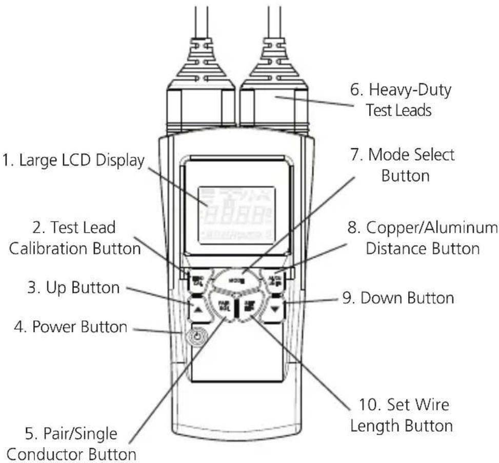
Figure 2-1. Cable Length Meter.
3. General Functions
3.1 PWR Key and Auto Power Off
Press the PWR key to turn the unit on and off. If no keys have been pressed, the Cable Length Meter powers off automatically after 10 minutes. The timer resets every time you press a key. In Tone mode, the unit will automatically power off after 1 hour.
3.2 Mode Key
The Cable Length Meter operates in eight modes. Press the "Mode" key to cycle through the various modes:
- AWG/mm/mm ^2 mode: measures cable length in AWG/mm/mm ^2 , feet/meters, copper/aluminum
- Coax mode: measures cable length, distance to opens, or distance to short
- Telco mode: measures cable length, distance to opens or distance to short
• Network: measures cable length, distance to opens, or distance to short - Ohm: measures resistance from 0 to 635 ohms
- Tone: generates four different tones
3.3 AL/CU Units Key
The AL/CU key functions in two ways.
Function #1: Press the AL/CU/Units key to select wire alloy type: copper (CU) or aluminum (AL). When selected, the "AL" or "CU" icon will light in the lower right corner of the display.
Function #2: Hold the AL/CU/Units key down for approximately 1.5 seconds. The unit will toggle between "Feet" or "Meters". When selected, the "FT" or "M" icon will light in the center right hand side of the screen.
3.4 LCD Display Icons
Table 3-1 describes the icons that appear on the LCD display.
Table 3-1. LCD display icons.
| Icon Description | |
| Coax mode | |
| Telco mode | |
| Network mode | |
| Tone mode | |
| Two-conductor icon (AWG/mm/mm ^2 mode) | |
| One-conductor icon (AWG/mm/mm ^2 mode) | |
| Short symbol, indicates the presence of a short between two conductors. An audible tone is also generated. (Coax, Telco, and Network mode) | |
| Unit detects voltage on the line | |
| Battery low icon. The Cable Length Meter monitors the battery status continuously when it is powered on. When the battery low icon is activated, the unit has approximately 15 minutes of battery life. Replace the battery as soon as possible. If the 15-minute period is exceeded, then cable testing results will become unreliable. | |
4. Using the Cable Length Meter
4.1 AWG Mode
This mode allows length measurements from 8 to 30 AWG (8, 10, 12, 14, 16, 18, 20, 22, 24, 26, 28, and 30 AWG). Use the UP/DOWN keys to scroll through the various wire gauges. Select from copper or aluminum type wires and meters or feet. Figure 4-1 shows a typical AWG Mode screen.
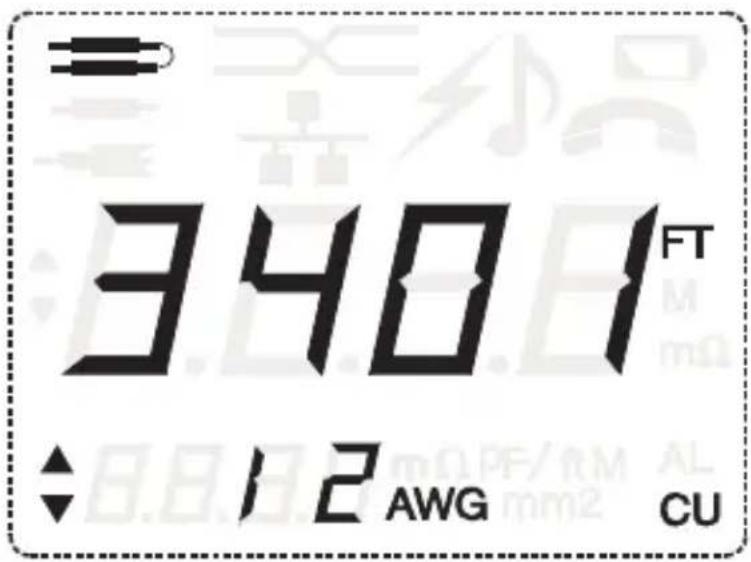
Figure 4-1. AWG Mode screen.
Table 4-1. AWG/mm/mm ^2 cross-reference data.
| AWG Diameter (mm) Area (mm | 2) | |
| #8 3.264 8.37 | ||
| #9 2.906 6.63 | ||
| #10 2.588 5.26 | ||
| #11 2.305 4.17 | ||
| #12 2.053 3.31 | ||
| #13 1.828 2.62 | ||
| #14 1.628 2.08 | ||
| #15 1.450 1.65 | ||
| #16 1.291 1.31 | ||
| #17 1.150 1.04 | ||
| #18 1.024 0.823 | ||
| #19 0.912 0.653 | ||
| #20 0.812 0.518 | ||
| #21 0.723 0.410 | ||
| #22 0.644 0.326 | ||
| #23 0.573 0.258 | ||
| #24 0.511 | 0.205 | |
| #25 0.455 0.162 | ||
| #26 0.405 0.129 | ||
| #27 0.361 0.102 | ||
| #28 0.321 0.081 | ||
| #29 0.286 0.064 | ||
| #30 0.255 0.051 | ||
4.2 Pair SGL Key
The Cable Length Meter can measure single- or two-conductor wires. Press the PAIR SGL key to toggle between single or two conductor. For single-conductor measurement, the unit is connected at both ends of the wire/conductor. For two-conductor measurements, the unit is connected one end of the wire and the other end of the pair is shorted (wire length = total resistance/2).
SET LEN Key (AWG Mode Example)
The Set Length function allows the user to change factory default ohms per feet coefficients values, based on a sample length of wire. Press the SET LEN key to toggle between the AWG Mode screen (Figure 4-1) and the Set Length Mode screen (Figure 4-2, below). In Set Length mode, the unit measures the sample wire's resistance. Press the UP/DOWN keys to adjust the wire length from 100 to 200 feet (31.3 to 62.5 m). The smaller digits display ohms per feet, based on the sample wire. Press and hold the SET LEN key down for a few seconds to store the new coefficients and override factory default values.
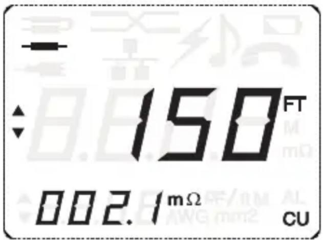
Figure 4-2. Set Length Mode screen.
Example: The factory default for 12 AWG copper is .0017 ohms/feet.
- Using the MODE key, select AWG mode.
-
Using the UP/DOWN keys, set the AWG to 12.
-
Press the SET LEN (LEN = Length) key, and the Set Length screen (Figure 4-2) appears. In this mode, use the UP/DWN keys to adjust the larger digits to match the length of the sample wire (100–200 ft. range). If the sample wire is 150 feet and its resistance is equal to 0.315 ohms, the smaller digits on the left-hand side of the screen will display "0.0021 ohms/ft. (150 feet/0.315 ohms = 0.0021 ohms/ft.)
- To store the new value, press the SET LEN key for approximately 1.5 seconds. The unit generates a confirmation beep. The new 12 AWG length coefficient of 0.0021 ohms/feet will be stored in memory in place of the factory default of 0.0017 ohms/feet.
NOTE: Restoring Factory Default Values. To restore factory coefficients back to their original values, hold the UP/DOWN keys and the Power key down at the same time when powering down the unit. Any previous values stored by the user will be deleted from memory. Table 4-2 lists the factory default values.
Table 4-2. Factory default values, ohms/feet.
| AWG Aluminum Copper | ||
| 8 0.00103 0.00063 | ||
| 10 0.00164 0.0011 | ||
| 12 0.00261 0.0017 | ||
| 14 0.00414 0.0025 | ||
| 16 0.00659 0.00455 | ||
| 18 0.0105 0.0061 | ||
| 20 0.0167 0.00945 | ||
| 22 0.0265 0.0168 | ||
| 24 0.0421 0.0273 | ||
| 26 0.067 0.0436 | ||
| 28 0.106 | 0.0637 | |
| 30 0.169 | 0.108 |
4.3 Coax, Network, and Telco Modes
Coax, Network, and Telco modes detect the distance to opens and the distance to shorts.
The Cable Length Meter determines the length by measuring line capacitance when the line is open or by measuring resistance when the line is shorted. When measuring opens, use the UP/DOWN keys to adjust the capacitance coefficient (10 to 40 pf per feet) to calculate the cable length. The Cable Length Meter supports three user-adjustable length coefficients, one for each type of cable (Coax, Network and Telco). It stores these coefficients in memory even when the unit is powered off.
Short/Resistance coefficients are stored in memory (see Table 4-2 for factory default values). These values can be changed by running the Set Length Function. The Set Length function allows the user to change factory default values, ohms per feet coefficients, based on a sample known length of wire. Press the SET LEN key to toggle between Normal Measuring screen (Figure 4-3) and Set Length Mode screen, Figure 4-4. In Set Length mode (line shorted), the unit will measure the resistance of the sample wire. Adjust the length of the sample wire using the UP/DOWN keys in the range of 100 to 200 feet. The smaller digits display the ohms per feet based on the sample wire. Press and hold the SET LEN key down for a few seconds to store the new coefficients.
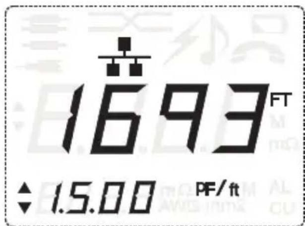
Figure 4-3. Normal Network Measuring screen.
Example: The factory default for Network wire is .0273 ohms per feet.
Press the MODE key to select Network mode.
Press the SET LEN (LEN = Length) key, and a new screen will pop up (see Figure 4-4). In this mode, use the UP/DOWN keys to adjust the larger digits to match the length of the sample wire (100–200 feet range). If the sample wire is 150 feet and its resistance is equal to .315 ohms, the smaller digits on the left hand side of the screen will display “002.1mΩ”.
To store the new value, press the SET LEN key for approximately 1.5 seconds. The unit will generate a confirmation beep. The unit stores the new network length coefficient of .0021Ω per feet in memory.
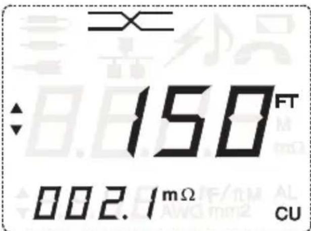
Figure 4-4. Set Length Mode screen.
NOTE: Restoring Factory Default Values. To restore ohms per feet factory coefficients back to their original values, hold the Power and UP/DOWN keys down at the same time while powering down the unit. Any previously stored values will be overwritten by the factory default values.
NOTE: To obtain symmetrical test results for Shorts and Opens measurements, the Cable Length Meter must have the correct "capacitance per feet coefficient" and "resistance per feet coefficient" of the wire under test.
Changing Opens/Capacitance Coefficient Using Set Length
To change capacitance coefficients, follow the steps above (cable/wire must be open) based on the sample wire (100 to 200 feet). The Cable Length Meter measures the total capacitance of the cable and displays the value in the lower left-hand corner of the LCD (the cable must be within 10 to 40 pf per feet range, otherwise meter will indicate OL).
Table 4-3. Opens/shorts factory default values.
| Mode Capacitance Opens Ohms per Feet/AWG Shorts | ||
| Coax 22.0 pf | 0.0663 ohms/NA | |
| Network 15.0 pf | 0.0273 ohms/24 AWG | |
| Telco 17.5 pf | 0.0273 ohms/24 AWG | |
natural_image
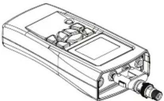
Technical line drawing of a mechanical device with internal components (no text or symbols)Figure 4-5. BNC-to-F connection for measuring coax.
4.4 Tone Mode
To generate a tone on the cable/wire, select Tone Mode (see Figure 4-6). The Cable Length Meter has four unique tones. Use the UP/DOWN keys, to scroll through the four tones. The tones generated match audio frequencies used with tone tracers/probes. The signal generated on a pair is nominal 5 volts peak-to-peak across the pair. The unit will power down automatically after 1 hour.
Available tones include:
-
High tone 1 KHz
-
Low tone 704 Hz
-
Warble tones, low tone for 160 ms, followed by 115 ms of high tone
-
Warble tones, low tone for 365 ms, followed by 65 ms of high tone.
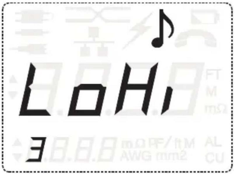
Figure 4-6. Tone Mode screen.
4.5 Calibrating the Test Lead
- Hold down the LEAD CAL key until the unit displays CAL. The unit will display CAL for a few seconds then display Shrt Lead.
- Short the leads as illustrated Figure 4-7. Once connected properly to the bus wire, press the LEAD CAL key again. The unit will beep and display OPEN LEAD.
- Disconnect the leads from the short. With the test leads open, press the LEAD CAL button. The unit will be beep and go into its normal operation mode. This completes the calibration procedure. This procedure must be done correctly for good measuring results.
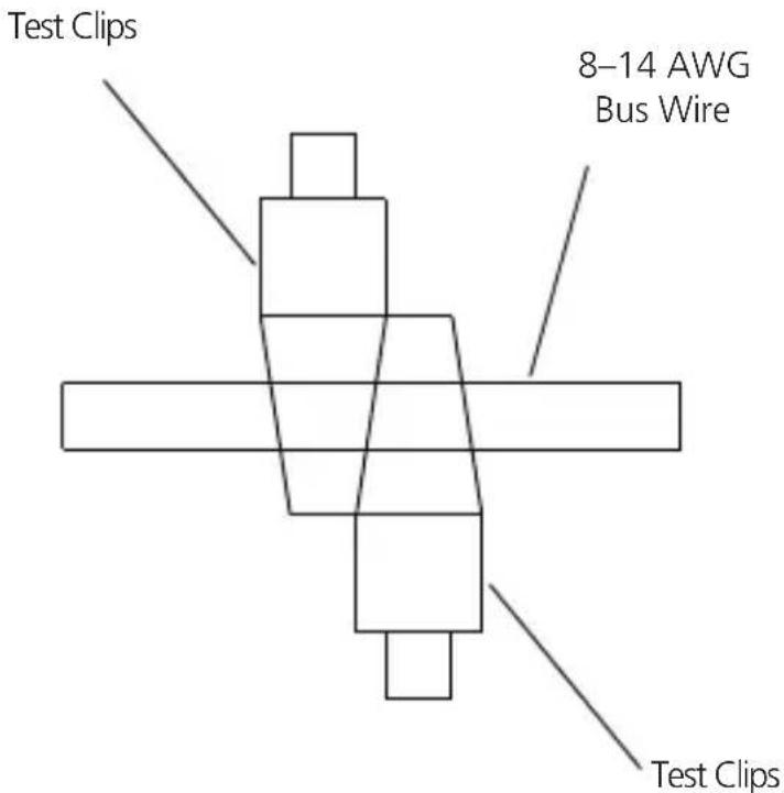
Figure 4-7. Wire under test.
NOTE: Make sure the wire surface is clean and the clips are making good contact. For best results, use solid wire 8 to 14 AWG. Make sure clips are as close together as possible.
5. Installing the Battery
Batteries are not included. Use only an alkaline 9-volt battery. When installing a new battery, disconnect any test cables connected to the Cable Length Meter. (See Figure 5-1.)
- Using a #2 Phillips screwdriver, unscrew the battery cover screw and remove the battery cover on the back of the unit.
- Remove the old battery from the battery compartment and detach the battery cap.
- Connect a new alkaline 9-volt battery to the battery cap.
- Slide the battery into the cavity.
- Close the battery cover and replace the screw. Do not overtighten.
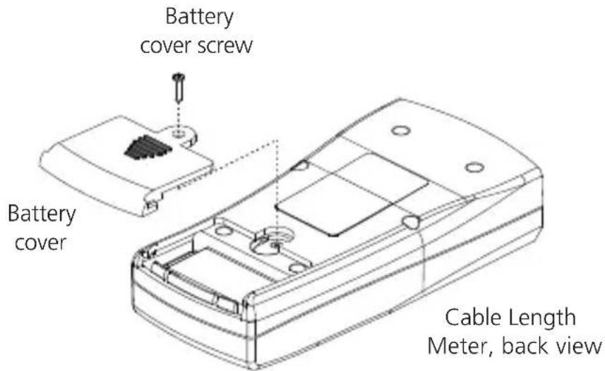
Figure 5-1. Battery installation.
6. Troubleshooting
6.1 Calling Black Box
If you determine that your Cable Length Meter is malfunctioning, do not attempt to alter or repair the unit. It contains no user-serviceable parts. Contact Black Box Technical Support at 724-746-5500.
Before you do, make a record of the history of the problem. We will be able to provide more efficient and accurate assistance if you have a complete description, including:
- the nature and duration of the problem.
- when the problem occurs.
• the components involved in the problem. - any particular application that, when used, appears to create the problem or make it worse.
6.2 Shipping and Packaging
If you need to transport or ship your Cable Length Meter:
- Package it carefully. We recommend that you use the original container.
- If you are returning the unit, make sure you include everything you received with it. Before you ship for return or repair, contact Black Box to get a Return Authorization (RA) number.
Black Box Tech Support: FREE! Live. 24/7.
Tech support the way it should be.

natural_image
Black-and-white photo of a smiling woman wearing a headset, no visible text or symbolsGreat tech support is just 20 seconds away at 724-746-5500 or blackbox.com.

BLACK BOX®
NETWORK SERVICES
About Black Box
Black Box Network Services is your source for more than 118,000 networking and infrastructure products. You'll find everything from cabinets and racks and power and surge protection products to media converters and Ethernet switches all supported by free, live 24/7 Tech support available in 20 seconds or less.
© Copyright 2009. All rights reserved.
- FEDERAL COMMUNICATIONS COMMISSION AND INDUSTRY CANADA
- RADIO FREQUENCY INTERFERENCE STATEMENTS
- WEEE Directive Compliance (RoHS)
- Normas Oficiales Mexicanas (NOM) Electrical Safety Statement
- Trademarks Used in This Manual
- Chapter Page
- Specifications
- Overview
- Introduction
- Features
- What's Included
- Hardware Description
- General Functions
- PWR Key and Auto Power Off
- Mode Key
- AL/CU Units Key
- LCD Display Icons
- Using the Cable Length Meter
- AWG Mode
- Pair SGL Key
- SET LEN Key (AWG Mode Example)
- Coax, Network, and Telco Modes
- Changing Opens/Capacitance Coefficient Using Set Length
- Tone Mode
- Calibrating the Test Lead
- Installing the Battery
- Troubleshooting
- Calling Black Box
- Shipping and Packaging
- BLACK BOX®
- About Black Box
Brand : Black Box
Model : CLM5000
Category : Cables for Computers and Peripherals