
HSA-100S - Audio/video converter Smart-AVI - Free user manual and instructions
Find the device manual for free HSA-100S Smart-AVI in PDF.


| Product Type | Audio/Video Converter |
| Brand | Smart-AVI |
| Model | HSA-100S |
| Input Interface | HDMI (Type A) |
| Output Interface | VGA (D-Sub 15-pin) + 3.5mm Audio Jack |
| Maximum Resolution | 1920 x 1080 @ 60Hz |
| Supported Video Formats | HDMI 1.3a, HDCP 1.2 |
| Audio Support | Stereo analog audio output |
| Power Supply | USB 5V DC (included cable) |
| Power Consumption | < 2.5W |
| Dimensions (L x W x H) | 9.5 x 5.5 x 2.2 cm |
| Weight | 120 g |
| Operating Temperature | 0°C to 60°C |
| Enclosure Material | Metal with plastic ends |
| LED Indicators | Power and signal status |
| Plug and Play | Yes, no additional software required |
| Maintenance | Clean with soft, dry cloth; avoid liquids |
| Safety | Keep away from water and extreme temperatures |
| Spare Parts | USB power cable, adapter not user-serviceable |
| Warranty | 1 year limited |
Frequently Asked Questions - HSA-100S Smart-AVI
User questions about HSA-100S Smart-AVI
0 question about this device. Answer the ones you know or ask your own.
Ask a new question about this device
Download the instructions for your Audio/video converter in PDF format for free! Find your manual HSA-100S - Smart-AVI and take your electronic device back in hand. On this page are published all the documents necessary for the use of your device. HSA-100S by Smart-AVI.
USER MANUAL HSA-100S Smart-AVI
natural_image
Front view of a Smart-AM network switch with ports, connectors, and I/O ports (no readable text or symbols beyond branding)Multi-format non-blocking audio, video, RS-232 and infrared distribution 8x8 matrix.
Controlled via software, remote control or over the Internet.
Notice:
The information contained in this document is subject to change without notice. SmartAVI makes no warranty of any kind with regard to this material, including but not limited to, implied warranties of merchantability and fitness for any particular purpose.
SmartAVI will not be liable for errors contained herein or for incidental or consequential damages in connection with the furnishing, performance or use of this material.
No part of this document may be photocopied, reproduced or translated into another language without prior written consent from SmartAVI.
Table of Contents
Chapter 1: Introduction ...... 4
What's in the Box 4
Overview 5
Applications 5
Chapter 2: Installation....6
Connecting the HDTV Router (Quick Start)....6
Connecting the HDTV Router (Detailed Instructions)....7
Video and Audio Inputs 7
Connecting the Communication Cable....7
System Power ON.... 10
Chapter 3: Software Installation and Operation.... 11
The Matrix Panel 12
The Button Panel....12
Macros....13
Chapter 4: Technical Information.... 14
Chapter 5: Appendices.... 15
RS232 Commands 17
IR Commands.... 18
Connection Help Sheet.... 22
Chapter 1: Introduction
What's in the box:
| Matrix | |
| HDC-MXS HDTV Component or UXGA + Audio over CAT5 8x8 Matrix with RS232 Control.Includes: [HDC-MX0808, CCRS232MF06, SM-CSW & (CCPWR06US)] | |
| Receivers | |
| XTP-RXS XTPRO UXGA/Audio/RS232/IR CAT5 Receiver with Dual Video support VGA connector for video and 3.5mm jack for audio | |
| XTP-RXLS XTPRO UXGA/Audio/RS232/IR CAT5 Long Range Receiver with Dual Video support VGA connector for video and 3.5mm jack for audio | |
| XTA-RXS XT-AV UXGA/Audio Receiver with VGA connector for video and jack 3.5mm for audio | |
| HDXP-RXS HDTV Video/Audio/RS232/IR CAT5 Receiver with Dual Video support 3 x RCA connector for video and RCA for audio | |
| HDC-VX-RXS Composite Video/Audio/Audio/IR CAT5 Point to Point Receiver 3 X RCA connector for video and RCA for audio | |
| Cables & Accessories | |
| SM-TCPS TCP/IP Control. Includes: [SMTCP, (CCRS232MM) & (PS5VD1A)] | |
| SM-EYE External Infrared Receiver; IR range of 10 to 30 ft. | |
| SM-LED IR Emitter 6 ft. single LED | |
| SM-CSW GUI software for source/destination selection and name editing for all SmartAVI Matrices/routers | |
| CCVGAMM06 6' male-to-male UXGA cable | |
| CCVGARCAMM06 6' VGA male-to-RCA male | |
| AD3.5MM2RCA Audio adapter from 3.5mm to 2 RCAs | |
| SM-RMT Remote Control type 1 |
Chapter 1: Introduction
Overview
At times multiple AV signals need to be transferred to multiple nearby output monitors. The HDTV Router allows multiple VGA/audio inputs to be routed to multiple outputs simultaneously, by way of a direct connection into the router.
The HDTV Router is a high-quality switching matrix for VGA type signals. All signal formats are catered for including VGA, SVGA, XGA, RGBHV and sync on green (SOG) applications. For ease of installation, Standard VGA connectors (HD15 sockets) are used for the input as well as the output video signal. All that is required is a standard pin-to-pin VGA cable to connect to the signal source.
Stereo audio can also be routed to multiple outputs. The audio can either be routed independently or together with the video signal using the SmartControl software that is very easy to use.
Note: for maximum signal performance, use only high quality cable that has internal coaxial cable for each color.
The units contain a very high bandwidth routing matrix for the Red, Green and Blue video channels.
Applications
Wall Displays •
Audio Visual Presentation•
Digital media •
Shopping centers •
Airports •
Security •
Dealer rooms •
Point of sale •
Control rooms •
Hotels •
Chapter 2: Installation
Connecting the HDTV Router (Quick Start)
Warning: As a precaution, we recommend that you disconnect all power cords and make sure that all devices are turned off.
Plug in all external audio/video sources to the back of the HDTV Router. (Inputs) 1.
Connect all external monitors and speakers to the back of the HDTV Router. (Outputs)2.
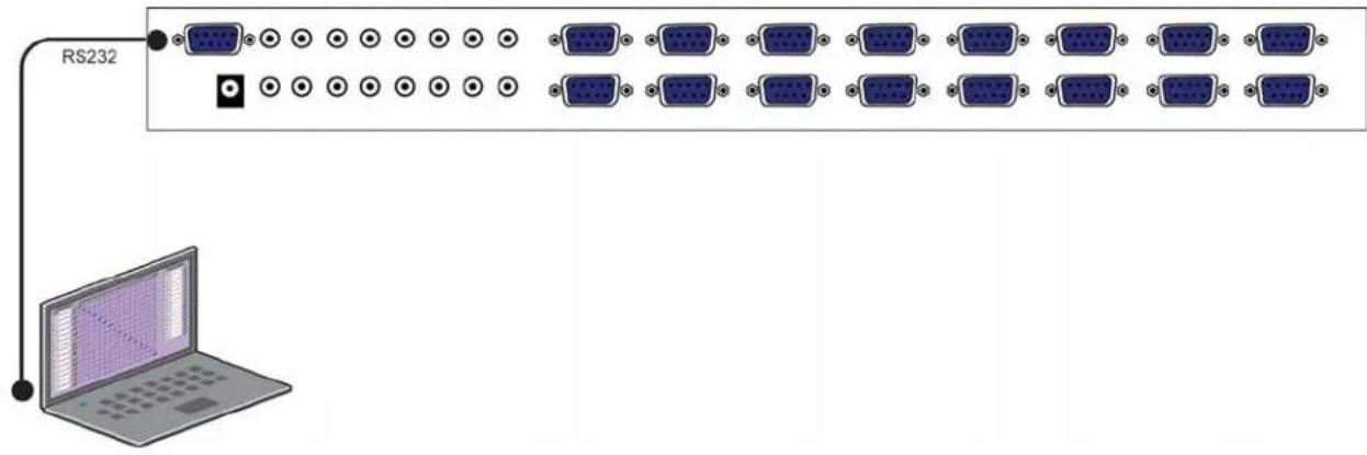
Connect a serial cable from the RS-232 port on your computer to the RS-232 port located on 3. the back panel of the HDTV Router unit.
Plug power cable into the HDTV Router unit. 4.
Install SmartControl software.5.
Power on the HDTV Router.6.
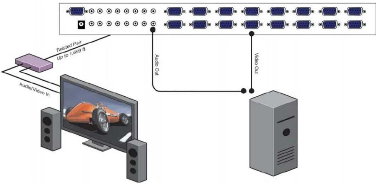
flowchart
graph TD
    A["Audio/Video In"] --> B["Twisted Pair Up to 1,669 ft."]
    B --> C["Video Out"]
    C --> D["Computer"]
Chapter 2: Installation
Connecting the HDTV Router (Detailed Instructions)
Video and Audio Inputs
The video input for the HDTV Router is a standard HD15 connection.
Connect all of the Input video sources to the back of the HDTV Router unit.
Hint: You may want to label the input video connections so as not to lose track of where the signal is coming from. Later on when the software is installed you will be able to give each connection a name and the software will remember it for you. This way you can switch the video connections without having to look at the physical connections on the back of the unit. (You can also use the included page at the end of this manual in order to keep track of the connections as you make them.)
The audio inputs for the HDTV Router are standard 3.5 mm Stereo Miniplug connectors.
Connect all of the audio inputs to the back of the HDTV Router unit. Many computer audio sources use this standard connection but there is other equipment such as receivers, and VCRs where a special adapter cable will be needed. Such as a 3.5mm miniplug to stereo RCA cable.
Make sure that the audio and video are coming from the same source and are plugged the same input number. For example, if the audio from one computer is connected to input 1, then the video should also be connected to input 1.
Video and Audio Outputs
The video and audio connections for the HDTV Router outputs are exactly the same. The only difference is that they are located on the left side of the back panel
Connect all of the external video monitors and corresponding speakers to the output connections located on the back of the SuperMatrix unit.


Chapter 2: Installation
Connecting the Communication Cable: RS-232
Each unit can be controlled by a RS-232 port connected from the back of the chassis. The SmartControl software will be used to control the units.
Connect the RS-232 cable the control computer by connecting the female RS-232 connector 1. into the male RS-232 connector of the PC. Turn the side screws so that it does not accidentally become disconnected
Connect RS-232 cable connector to the male RS-232 connector on the back of the chassis. 2.
Chapter 2: Installation

flowchart
graph TD
    A["Computer"] -->|Video Out| B["Front Monitor"]
    A -->|Audio Out| B
    C["Computer"] -->|Video Out| D["Front Monitor"]
    C -->|Audio Out| D
    E["Computer"] -->|Video Out| F["Front Monitor"]
    E -->|Audio Out| F
    G["Computer"] -->|Video Out| H["Front Monitor"]
    G -->|Audio Out| H
    I["Control Interface"] --> J["Receiver XTAV/XTPro"]
    J -->|From Front of Box| K["Computer"]
    J -->|CAT5/RJ45 Twisted Pair| L["Front Monitor"]
    L --> M["Input to HDTV Router"]
    L --> N["Output to Monitor/Audio"]
    O["RF6201"] --> P["SmartAM"]
    Q["RS-232"] --> R["Front Monitor"]
    S["Video Out"] --> T["Front Monitor"]
    U["Audio Out"] --> V["Front Monitor"]
    W["Video Out"] --> X["Front Monitor"]
    Y["Audio Out"] --> Z["Front Monitor"]
    AA["Input to HDTV Router"] --> AB["Computer"]
    AC["Output to Monitor/Audio"] --> AD["Front Monitor"]
HDTV Router connection diagram
System Power ON
You are now ready to turn on the system. Make sure that all connections are plugged in and all video monitors and speakers that you wish to use are connected.
Plug in the power cord to the back of the 1. HDTV Router unit. Connect this power cord to the wall.
Turn computer on and make sure that the boot up process has completed.2.
Observe to see if LEDs are lit. The 3. HDTV Router unit has two. One of those LEDs is for the power and the other is to indicate that the unit is functioning properly.
Power on all external monitors and speakers.4.
Chapter 3: Software Installation & Operation
Find the Installation CD that came with your HDTV Router unit. This CD has the SmartControl software that you will need in order to control the unit using a computer.
Insert the CD into your CD-ROM. On the CD you should see:
SmartControl Installer.exe
SmartControl Help File •
HDTV Router Manual in PDF format •
Double click SmartControl.exe in order to initiate software installation. Click Install. After installation has completed, click CLOSE.
In order to use the software, click on the START button>Programs>SmartControl. There you should see a help file, the SmartControl launcher as well as a shortcut to uninstall SmartControl. Click on SmartControl in order to launch the software.
When the software starts you will see a screen like this.

Advanced Configuration: If you have more than one Router installed you will want to check this box.
Router Type: Select SuperMatrix.
A/V Split: Check this box if you need to route audio and video independently, regardless from which source they originated from. Leave unchecked if you want audio and video signals from the same input to remain together.
For example, if you wanted to route different video feeds to different locations but wanted all of them to have the same audio, you should check the box.
Chapter 3: Software Installation & Operation
Inputs/Outputs: Enter the number of Inputs/Outputs your HDTV Router has. For now we will assume that there are 16 inputs and 16 outputs.
Com Port: Select the appropriate com port that your computer is using to access the router.
Router Timeout: By default this is 0 meaning the computer acknowledges commands almost instantly. Sometimes a computer takes longer to respond. This setting should be left at 0. If you need to change it, it should be no higher than 0.2.
After you have entered in the necessary information click OK.
This will now take you to the Main Routing Window where you can route the different video/audio connections.

On this screen you will notice the input buttons running down the left side while the output buttons run across the top. They are each labeled 1 through 16.
Note: The three small colored buttons at the lower right labeled ALL, VIDEO, and AUDIO are not available if AV Split was not checked when you configured your router.
Chapter 3: Software Installation & Operation
The Main Routing Window enables you to control the router(s) connections by means of the matrix panel, the button panel, or with pre-recorded routes called macros.
Matrix Panel: This is probably the simplest way to route the connections. Simply click on the cross point itself. The input on the left will then be routed to the output above.
Note: Inputs can be routed to several different outputs, but each output can only have a single input at any one time. So you can have several connections horizontally but not vertically.
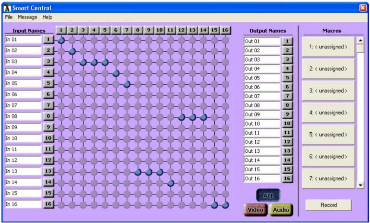
The Button Panel: These are the numbered buttons across the top and left sides. Click an output button on the top, and then click an input button on the left.
Options for using the Button Panel
Output Options: •
To select multiple outputs next to each other, click on one output, then hold the shift key down and click the last output. When the input is clicked, it is routed to all selected outputs
To select multiple outputs individually, hold the control key down and click on any number of outputs. When the input is clicked, it is routed to all selected outputs.
Input Options: •
To route an input to all the outputs at once, hold the control key down and click on an input.
To leave the outputs selected after the route is made, hold the shift key down and click on an input.
Chapter 3: Software Installation & Operation
Macros: This section of the window is used to save and play back macros. Macros store a set sequence of routes.
To record a macro:
Click on the Record button (last button shown above). A blinking "recording" message below 1. this button will be displayed to indicate that all routes are being recorded.
Select the desired cross points. (See Matrix Routing for details on making these routes.) There is 2. no limit on the number of routes you may record.
If you click a macro button while in the record mode, the macro will be executed, and these 3. routes will be added to the recording. This makes it possible to combine the routes of two or more macros into one bigger macro.
When finished, click the "Save Macro" button. You will be instructed to then click on one of the 4. macro buttons. Doing this will save the recorded routes to that button.
To cancel saving the macro, click the "Cancel Save" button.
To play back a macro, simply click on one of the 50 macro buttons. Use the scrollbar to bring 5. any of these into view.
The macros are automatically saved in the current configuration file. They are also saved when 6. you select the File/Save Configuration... menu.
To save macros in a separate file for a special purpose, select the File/Save Macros...menu.
Chapter 4: Technical Information
| HDTV Router SPECIFICATIONS | |
| Video | |
| Bandwidth 400 MHz | |
| Input Signal Level 1 Volt pk-pk into 75R | |
| Output Impedance 100 Ohms | |
| Input Impedance 75 Ohms | |
| Connector 8 x HD15 socket female | |
| Format VGA/SVGA/XGA/RGBHV/RGsB/CVBS/YC/YUV/RGBS | |
| Syncs TTL5VDC | |
| Bandwidth Horizontal Sync up to 85KHz | |
| RS-232 8 x RS232 DB9 Female, TX, RX, GND | |
| Infrared 8 x IR 3.5mm Jack to IR emitter | |
| Back Panel 8 x RJ45 with video, audio and data modulated within single UTP | |
| Audio | |
| Signal 15KHz 0dB unbalanced 100 Ohms impedance | |
| Connector RCA or 3.5 Stereo Jack x 8 | |
| Control | |
| IR 3.5mm connector with 38khz x 8 | |
| DB9 female RS232 or RS422 @ 9600bps - DB9 Female | |
| Power Supply | |
| 5V DC-3A | |
| Dimensions | |
| Height X Width X Depth 2.73" (69.34mm) x 19"(482.6mm) x 17.72"(450mm) | |
| Weight 9 lbs. | |
Chapter 4: Technical Information
XTPRO SPECIFICATIONS
| Receiver with dual monitors, Audio and IR/RS-232 support | |
| VGA Data | |
| Format | RGBHV, RGsB, YUV, Y/C, CVBS |
| Resolution | Up to 1900 x 1200 VGA, SVGA, XGA, SXGA |
| Connector Type | HD 15 socket |
| Audio | |
| Signal Type | Stereo unbalanced |
| Connector Type | 3.5mm jack socket |
| Infrared | |
| Signal Type | 30 to 110Khz |
| Connector Type | 3.5mm socket |
| RS-232 | |
| Speec | 2400 to 115Kbps |
| Connector Type | DB9 Male |
| Power | |
| Requirements | 5VDC @ .5A |
| Connector | 2.1mm DC jack (center +ve) |
| Physical | |
| Dimensions | 135 x 90 x 23mm ( 26 with pegs) |
| Weight | 8 lbs or .36 kg |
natural_image
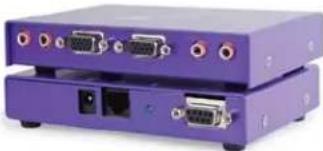
Purple electronic device with multiple ports and connectors (no visible text or symbols)HD-Lite SPECIFICATIONS
| TRANSMITTER AND RECEIVER |
| VideoBandwidth 400MHz, Analog signal Level 1 volt, Impedance 75 ohms |
| Connector3 RCA |
| FormatYPbPr analog component video |
| AudioBandwidth 20 KHz, Signal level O dB, Impedance 10K ohms, Connector RCA Left and Right |
| System and CableType Cat5 UTP EIA 568A, Connector RJ45 |
| PowerRequirements 5V DC @500mA, Connector 5x2.1 DC Jack |

natural_image
Exterior view of a black electronic device with ports and connectors (no visible text or symbols)XTAV SPECIFICATIONS
| Receiver with Video and Audio support | |
| VGA Data | |
| Format | RG BHV, RGsB, YUV, Y/C, CVBS |
| Resolution | Up to 1900 x 1200 VGA, SVGA, XGA, SXGA |
| Connector type | HD 15 socket |
| Audio | |
| Signal Type | Stereo unbalanced |
| Connector | 3.5mm jack socket |
| Power | |
| Requirements | 5VDC @ .5A |
| Connector | 2.1mm DC jack (center +ve) |
| Physical | |
| Dimensions | 90 x 90 x 23mm (26 with pegs) |
| Weight | .6 lbs or .36 kg |

natural_image
Two purple electronic devices with ports and connectors, no visible text or symbolsHD-XT SPECIFICATIONS
| TRANSMITTER AND RECEIVER |
| VidecBandwidth 400MHz, Analog signal Level 1 volt, Impedance 75 ohms |
| Co nrector3 RCA |
| Forma1YPbPr analog component video |
| AudioBandwidth zu KHz, signal level odB, Impedance 1 uK ohms, Con- nrector RCA Left and Right |
| system and CableType Cat5 UTP EIA 568A, Connector RJ45 |
| PowerRequirements 5V DC @500mA, Connector 5x2.1 DC Jack |
| Rs2s2DB9 Male/Female, baudrate up to 115,000 bps |
| RIR Emitter Output, IR Frequency Range:30KHz to 80KHzEmitter Distance: Up to 10', Connector: 3.5mm stereog ack for emitter |

natural_image
Exterior view of a black electronic device with ports and connectors (no visible text or symbols)Chapter 5: Communication Protocol
Where;
Response: If successful the unit will respond with an ACK (0x06)
Examples
-
Sending the following byte string sets Source 1 to Destination 1 on chassis 0 0xBE,0xEF,0x00,0x00,0x00,0x00,0x00,0x51,
-
Sending the following byte string sets Source 2 to Destination 1 on chassis 0 0xBE,0xEF,0x00,0x00,0x00,0x01,0x00,0x50,
-
Sending the following byte string sets Source 2 to Destination 2 on chassis 0 0xBE,0xEF,0x00,0x00,0x00,0x01,0x01,0x51,
-
Sending the following byte string sets Source 16 to Destination 16 on Frame 15 0xBE,0xEF,0x0F,0x00,0x00,0x0F,0x0F,0x5E,
7.2 Send Message Command : CMD = 0x01
Writes message to specified On Screen Display.
Send:
<0xBE><0xEF><Address><0x00><0x01><Destination><OSDLine><Message>
<BCC>
Where;
(Please see the following text for more details on this)
Due to the limitations of both the On Screen Display and the amount of available non-volatile memory in the SmartNet it is necessary for the Host system to perform some pre-processing of the message to be displayed.
The characters in the message to be displayed need to be translated using the rules detailed in Appendix B.
Response: If successful the unit will respond with an ACK (0x06)
Examples
-
Sending the following byte string sends the text "Message" to Line 2, destination 1 of Switch 0 BE, EF, 00, 00, 01, 00, 02, 18, 2E, 3C, 3C, 2A, 30, 2E, 0B, 0B, 0B, 0B, 0B, 0B, 0B, 0B, 0B, 0B, 0B, 0B, 0B, 0B, 0B, 0B, 0B, 0B, 5B,
-
Sending the following byte string sends the message "Abandon Ship!" to line 6, destination 6 of switch 5 BE, EF, 04, 00, 01, 05, 06, 0C, 2B, 2A, 37, 2D, 38, 37, 0B, 1E, 31, 32, 39, 0B, 0B, 0B, 0B, 0B, 0B, 0B, 0B, 0B, 0B, 0B, 0B, 0B, 0B, 60,
Set Video Only Crosspoint
Cmd = 3
Databytes = destination, source
i.e. to switch video on output 3 to input 4
CMD = 3
Databytes = 3,4
Chapter 5: Communication Protocol
Set Audio Only Crosspoint
Cmd = 4
Databytes = destination, source
i.e. to switch audio on output 3 to input 4
CMD = 3
Databytes = 3,4
Mute Video on specified output
Cmd = 5
Databytes = Destination, State (0=off, 1=on)
i.e. to turn video off on output 3
CMD=5
Databytes = 3,0
i.e. to turn video on on output 3
Mute Audio on specified output
Cmd = 6
Databytes = Destination, State (0=off, 1=on)
i.e. to turn audio off on output 3
CMD=6
Databytes = 3,0
i.e. to turn video on on output 3
CMD=6
Databytes = 3,1
Split Crosspoints - Video and Audio Differently
Cmd = 7
Not specified yet but will exist
Get Current Status
CMD 8 = current Status all
Databytes = Destination. (1-16 = specific output, 0xff = all)
i.e. to read the status of output 3 send;
CMD = 8
Databyte = 3
i.e. to read the status of all outputs
CMD=8
Databytes = 0xff
Unit will return Valid PSU as above where databytes is;
a single byte indicating currently selected source if specific destination was requested
or a string of 16 bytes indicating currently selected source for each destination starting with destination 1.
Chapter 5: Communication Protocol
The command to make the end of CAT5 line receiver (SLRX-RX300) switch between its local and remote sources is as follows;
<0xBE><0xEF>
Where;
<0xBE> always 0xBE
<0xEF> always 0xEF
Frame address. Set by Hex switch on unit or position in Rack frame.
So if switching the Receiver on output 3 of Frame 2 to its local source send
<0xBE><0xEF><0x02><0x00><0x32><0x02>
Get System Information
Cmd = 0xff
Databytes = NULL (none)
Unit will return a valid PSU as detailed above where Databytes are as follows
Where Product Type =
1 Byte;
0 = SmartNet V
1 = SmartNet X
3 = SLX-TX550
4 = SLX-RX300
Where Switch configuration =
2 Bytes;
Where Version =
3 bytes
Appendix A: RS232/422 Converter and Comms Cable
RS232/RS422 Converter
A suitable RS232/RS422 product can be purchased from KK Systems in Brighton, East
Chapter 5: Communication Protocol
Comms Cable
| DB9 cable ended plug Function UTP Wire Colours (RJ45) | ||
| 1 | - | - |
| 2 RX-(A) Orange | ||
| 3 TX+(B) White & Brown | ||
| 4 0V Blue | ||
| 5 | - | - |
| 6 0V Green | ||
| 7 RX+(B) White & Orange | ||
| 8 TX-(A) Brown | ||
| 9 | - | - |
You will also require a cable that sits between the RS422 port of the K2 converter and the Frame. It should be wired as shown below. (Tip: Cut the end off a CAT5 Patch lead and attach a DB9 Plug)
Appendix B: On Screen Display Message Processing Rules.
Available on SmartNet-V only
Due to the limitations of both the On Screen Display and the amount of available non-volatile memory in the SmartNet it is necessary for the Host system to perform some pre-processing of the message to be displayed.
The message string needs to be parsed character by character and the values translated according to the table below.
| Characters Translation Rule Comment | ||
| "0" Through "9" ChrAsc|sChar - 48) Subtract 48 from ASCII value of character | ||
| "A" Through "Z" | Chr{Asc|sChar} - 53) Subtract | 53 from ASCII value of character |
| "a" Through "z" | ChrAsc|sChar - 55) Subtract | 55 from ASCII value of character |
| "." | Chr{&H27} | Substitute the character "." for ASCII value 0x27 |
| " " {space} | Chr&H0b | Substitute the character " " for ASCII value 0x0b |
| "." | Chr{&H26} | Substitute the character " " for ASCII value 0x26 |
| "/" | Chr&H28 | Substitute the character "/ " for ASCII value 0x28 |
| ""Apostrophe Chr{&H29} | Substitute the character "" " for ASCII value 0x29 | |
| "- | Chr&H0A | Substitute the character "-" for ASCII value 0x0a |
| "?" | Chr{&H70} | Substitute the character "?" for ASCII value 0x70 |
| "*" | Chr&H5F | Substitute the character "* " for ASCII value 0x5f |
| "- | Chr{&H78} | Substitute the character "- " for ASCII value 0x78 |
| "> | Chr&H7A | Substitute the character "> " for ASCII value 0x78 |
| <" | Chr{&H7B} | Substitute the character "< " for ASCII value 0x7b |
| "!" | Chr&H61 | Substitute the character "| " for ASCII value 0x61 |
| "!" | Chr{&H62} | Substitute the character "| " for ASCII value 0x62 |
Please see the following page for a working example of these rules in the form of a Visual BASIC function.
Chapter 5: Communication Protocol
Appendix B: Continued..... (Sample Translation routine in Visual BASIC)
Function LookUp OSDString(sTextMessage As String) As String
' Look up chars and translate to message for OSD
Dim iLoop As Integer
Dim sNewMess As String
Dim sChar As String
sNewMess = Space$(MAX_SCREEN_CHAR)
For iLoop = 1 To Len(sTextMessage)
sChar = Mid$(sTextMessage, iLoop, 1)
Select Case sChar
Case "0" To "9"
Mid(sNewMess, iLoop, 1) = Chr(Asc(sChar) - 48)
Case "A" To "Z"
Mid(sNewMess, iLoop, 1) = Chr(Asc(sChar) - 53)
Case "a" To "z"
Mid(sNewMess, iLoop, 1) = Chr(Asc(sChar) - 55)
Case "."
Mid$(sNewMess, iLoop, 1) = Chr(&H27)
Case ""
Mid$(sNewMess, iLoop, 1) = Chr(&HB)
Case ":""
Mid$(sNewMess, iLoop, 1) = Chr(&H26)
Case "/"
Mid$(sNewMess, iLoop, 1) = Chr(&H28)
Case ""
Mid$(sNewMess, iLoop, 1) = Chr(&H29)
Case "-""
Mid$(sNewMess, iLoop, 1) = Chr(&HA)
Case "?""
Mid$(sNewMess, iLoop, 1) = Chr(&H70)
Case "*"
Mid$(sNewMess, iLoop, 1) = Chr(&H5F)
Case "=""
Mid$(sNewMess, iLoop, 1) = Chr(&H78)
Case ">"
Mid$(sNewMess, iLoop, 1) = Chr(&H7A)
Case "<"
Mid$(sNewMess, iLoop, 1) = Chr(&H7B)
Case "|""
Mid$(sNewMess, iLoop, 1) = Chr(&H61)
Case ")"
Mid$(sNewMess, iLoop, 1) = Chr(&H62)
Case Else
Mid$(sNewMess, iLoop, 1) = Chr(&HB)
d Select
Next iLoop
LookUpOSDString = sNewMess
End Function
Chapter 6: Appendices
Limited Warranty Statement
A. Extent of limited warranty
-
SmartAVI Technologies, Inc. warrants to the end-user customers that the SmartAVI product specified above will be free from defects in materials and workmanship for the duration of 1 year, which duration begins on the date of purchase by the customer. Customer is responsible for maintaining proof of date of purchase.
-
SmartAVI limited warranty covers only those defects which arise as a result of normal use of the product, and do not apply to any:
a. Improper or inadequate maintenance or modifications
b. Operations outside product specifications
c. Mechanical abuse and exposure to severe conditions
-
If SmartAVI receives, during applicable warranty period, a notice of defect, SmartAVI will at its discretion replace or repair defective product. If SmartAVI is unable to replace or repair defective product covered by the SmartAVI warranty within reasonable period of time, SmartAVI shall refund the cost of the product.
-
SmartAVI shall have no obligation to repair, replace or refund unit until customer returns defective product to SmartAVI.
-
Any replacement product could be new or like new, provided that it has functionality at least equal to that of the product being replaced.
-
SmartAVI limited warranty is valid in any country where the covered product is distributed by SmartAVI.
B. Limitations of warranty
TO THE EXTENT ALLOWED BY LOCAL LAW, NEITHER SMARTAVI NOR ITS THIRD PARTY SUPPLIERS MAKE ANY OTHER WARRANTY OR CONDITION OF ANY KIND WHETHER EXPRESSED OR IMPLIED, WITH RESPECT TO THE SMARTAVI PRODUCT, AND SPECIFICALLY DISCLAIM IMPLIED WARRANTIES OR CONDITIONS OF MERCHANTABILITY, SATISFACTORY QUALITY, AND FITNESS FOR A PARTICULAR PURPOSE
C. Limitations of liability
To the extent allowed by local law the remedies provided in this warranty statement are the customers sole and exclusive remedies
TO THE EXTENT ALLOWED BY LOCAL LAW, EXCEPT FOR THE OBLIGATIONS SPECIFICALLY SET FORTH IN THIS WARRANTY STATEMENT, IN NO EVENT WILL SMARTAVI OR ITS THIRD PARTY SUPPLIERS BE LIABLE FOR DIRECT, INDIRECT, SPECIAL, INCIDENTAL, OR CONSEQUENTIAL DAMAGES WHETHER BASED ON CONTRACT, TORT OR ANY OTHER LEGAL THEORY AND WHETHER ADVISED OF THE POSSIBILITY OF SUCH DAMAGES.
D. Local law
To the extent that this warranty statement is inconsistent with local law, this warranty statement shall be considered modified to be consistent with such law.
Chapter 6: Appendices
| Input Description Output Description | |||
| 1 | 1 | ||
| 2 | 2 | ||
| 3 | 3 | ||
| 4 | 4 | ||
| 5 | 5 | ||
| 6 | 6 | ||
| 7 | 7 | ||
| 8 | 8 | ||
| 9 | 9 | ||
| 10 10 | |||
| 11 11 | |||
| 12 12 | |||
| 13 13 | |||
| 14 14 | |||
| 15 15 | |||
| 16 16 | |||
| 17 17 | |||
| 18 18 | |||
| 19 19 | |||
| 20 20 | |||
| 21 21 | |||
| 22 22 | |||
| 23 23 | |||
| 24 24 | |||
| 25 25 | |||
| 26 26 | |||
| 27 27 | |||
| 28 28 | |||
| 29 29 | |||
| 30 30 | |||
| 31 31 | |||
| 32 32 | |||
SmartAVI, Inc.
11651 Vanowen St.
North Hollywood, CA 91605
Tel (818) 503-6200 Fax (818) 503-6208
Email: info@smartavi.com
- Notice:
- Table of Contents
- Chapter 1: Introduction
- Overview
- Applications
- Chapter 2: Installation
- Connecting the HDTV Router (Quick Start)
- Connecting the HDTV Router (Detailed Instructions)
- Video and Audio Outputs
- Connecting the Communication Cable: RS-232
- System Power ON
- Chapter 3: Software Installation & Operation
- Chapter 4: Technical Information
- Chapter 5: Communication Protocol
- Where;
- Examples
- Send:
- Chapter 6: Appendices
- Limited Warranty Statement
- Extent of limited warranty
- Limitations of warranty
- Limitations of liability
- Local law
Brand : Smart-AVI
Model : HSA-100S
Category : Audio/video converter