
FIN-180P - Air Conditioning BROAN - Free user manual and instructions
Find the device manual for free FIN-180P BROAN in PDF.


User questions about FIN-180P BROAN
0 question about this device. Answer the ones you know or ask your own.
Ask a new question about this device
Download the instructions for your Air Conditioning in PDF format for free! Find your manual FIN-180P - BROAN and take your electronic device back in hand. On this page are published all the documents necessary for the use of your device. FIN-180P by BROAN.
USER MANUAL FIN-180P BROAN
natural_image
Technical line drawing of a mechanical device with a cylindrical component and connecting rod (no text or symbols)FIN-180P
6-FT. POWER CORD
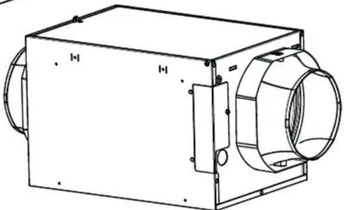
natural_image
Technical line drawing of a mechanical device with cylindrical and rectangular components (no text or symbols)FIN-180P-HW
HARDWIRED
VB0260
REGISTER YOUR PRODUCT ONLINE AT: www.broan-nutone.com/register
⚠️RESIDENTIAL USE ONLY⚠️
READ AND SAVE THESE INSTRUCTIONS
Please take note that this manual uses the following symbols to emphasize particular information:
⚠ WARNING
Identifies an instruction which, if not followed, might cause serious personal injuries including possibility of death.
CAUTION
Denotes an instruction which, if not followed, may severely damage the unit and/or its components.

Indicates a supplementary information that may relate to optional parts or simply aim to facilitate a task.
⚠ WARNING
TO REDUCE THE RISK OF FIRE, ELECTRIC SHOCK, OR INJURY TO PERSON(S) OBSERVE THE FOLLOWING:
- Use this unit only in the manner intended by the manufacturer. If you have questions, contact the manufacturer.
- Before servicing or cleaning this unit, turn power off at service panel.
- This unit is not designed to provide combustion and/or dilution air for fuel-burning appliances.
- Do not use this unit with any solid-state speed control device other than the one specified in section 4.
- FIN-180P MODEL ONLY: Do not operate any fan with a damaged cord or plug. Discard fan or contact your HVAC contractor, or the manufacturer.
- FIN-180P MODEL ONLY: Do not run cord under carpeting. Do not cover cord with throw rugs, runners or similar coverings. Do not route cord under furniture or appliances. Arrange cord away from traffic area and where it will not be tripped over.
- Installation work and electrical wiring must be done by qualified person(s) in accordance with all applicable codes and standards, including fire-rated construction.
- When cutting or drilling into a wall or ceiling, do not damage electrical wiring and other hidden utilities.
- ALL UNITS: This unit must be grounded. FIN-180P MODEL ONLY: The power supply cord has a 3-prong grounding plug for your personal safety. It must be plugged into a mating 3-prong grounding receptacle, grounded in accordance with the national electrical code and local codes and ordinances. Do not remove the ground prong. Do not use an extension cord.
- When servicing, cleaning or performing installation of this unit, it is recommended to wear safety glasses and gloves.
- When applicable local regulation comprises more restrictive installation and/or certification requirements, the aforementioned requirements prevail on those of this document and the installer agrees to conform to these at his own expenses.
- The unit must be mounted at least 3.3 feet (1.0 meter) away from any accessible opening of the duct.
CAUTION
- Please read specification label on product for further information and requirements.
- Do not intake air into spaces within walls or ceiling or into attics, crawl spaces, or garage. Do not attempt to recover the exhaust air from a dryer or a range hood.
- Intended for residential installation only in accordance with the requirements of NFPA 90B.
- When leaving the house for a long period of time (more than two weeks), a responsible person should regularly check if the unit operates adequately.
- At least once a year, the unit mechanical and electronic parts should be inspected by qualified service personnel.
- Since the electronic control system of the unit uses a microprocessor, it may not operate correctly because of external noise or very short power failure. If this happens, unplug the unit's low voltage power source and wait approximately 10 seconds. Then, plug the low voltage in again.
- Outdoor intake hood must be weather tight and comprise a bird screen.
- Should you decide to dispose of this unit or of parts of it, do so in accordance with local laws and regulation.
- Some areas are prone to a higher frequency of lightning-induced power surges. Using a surge protector device to protect units located in these areas is recommended.
TABLE OF CONTENTS
1. USER INFORMATION ....4
1.1 Optional Wall Control....4
1.2 User Servicing Instructions....4
1.3 Comfort Mode 4
2. PLANNING ....5
2.1 Installation zones 5
2.2 Installation types 5
2.2.1 Stand Alone Installation....5
2.2.2 Installation with an AHU 5
3. PREPARATION ......6
3.1 Mounting the Unit 8
3.1.1 Flush-to-Ceiling 8
3.1.2 Under Ceiling or Wall Mounted....9
3.1.3 Ceiling Hung 9
3.1.4 In the Attic....9
3.2 Connecting the Insulated Ducts to the Unit 10
3.3 Connect Power 10
3.3.1 FIN-180P 10
3.3.2 FIN-180P-HW 11
4. HOW TO TEST THE UNIT ......11
5. WIRING 12
5.1 Wiring and Logic Diagrams 12
5.2 Connection to the AHU 13
5.3 Connection to the VT11W Optional Wall Control 13
6. SERVICE PARTS ......14
7. TROUBLESHOOT ....15
7.1 FIN-180P Troubleshoot.... 15
7.2 FIN-180P-HW Troubleshoot 16
7.3 All Units Troubleshoot....17
8. WARRANTY....18
9. APPENDIX A ......19
10. APPENDIX B....20
1.1 OPTIONAL WALL CONTROL
This unit can be connected to the VT11W wall control.
- Upon startup, the wall control LED will light up during the boot sequence, and remain ON as the unit starts to operate after the boot sequence. Press the push button to turn the unit OFF; the wall control LED will also turn OFF.
- When it is time to perform the filter maintenance, the wall control LED will blink slowly (2 seconds ON, 2 seconds OFF). After the filter maintenance has been performed, press and hold the push button for 5 seconds to reset the filter maintenance reminder.
• Refer to your installer for any other blinking pattern.
1.2 USER SERVICING INSTRUCTIONS
- The metal filter included with this unit should be cleaned every 6 months using water and a mild soap. To remove the filter(s), open the door, release the filter retaining clip and pull filter(s) out. Allow the filter to dry completely before putting it back in the unit; when reinserting it in the unit, make sure that it is standing straight.
- Inspect the outdoor air intake at least once a year.
- During the first year of operation, it is recommended to inspect your unit at a higher frequency, especially if you live near a highway or in an area where there is a lot of construction work, generating lots of dust. Your filter(s) may need more frequent cleaning or replacement in these types of environments.
- Replace the optional MERV filter at least once a year; do not attempt to clean and reuse the optional MERV filter.
• These recommendations may change according to the environmental conditions in your area.
1.3 COMFORT MODE
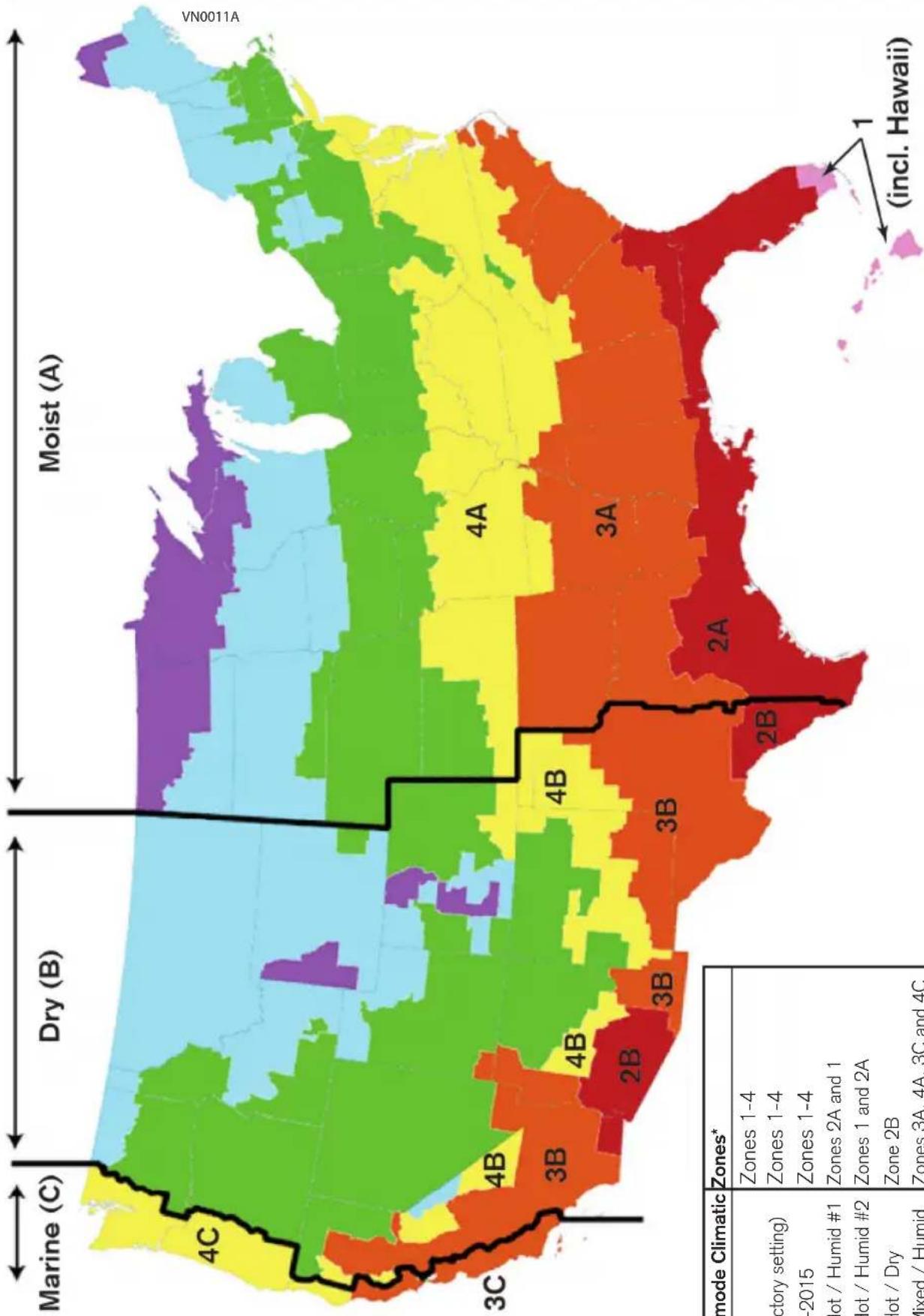
Should the air inside your house become too humid, or if such conditions want to be prevented, the operation mode of your Supply Fan can be changed from a Code-Compliant one (modes 1 to 3) to a Comfort Mode (modes A to E). Refer to the map in Appendix A to make the right choice.
When making such change, make sure to only change the Mode and to leave the Run time % as it was set by your installer. If in doubt, refer to your HVAC contractor.
| Selected mode Climatic Zones* | |
| 1 - Ashrae 2016 Zones 1-4 | |
| 2 - Ashrae 2010 (factory setting) Zones 1-4 | |
| 3 - IRC / IMC 2012-2015 Zones 1-4 | |
| A - Comfort mode Hot / Humid #1 Zones 2A and 1 | |
| B - Comfort mode Hot / Humid #2 Zones 1 and 2A | |
| C - Comfort mode Hot / Dry Zone 2B | |
| D - Comfort mode Mixed / Humid Zones 3A, 4A, 3C and 4C | |
| E - Comfort mode Mixed / Dry Zones 3B and 4B | |
*As defined by the Department of Energy. Refer to the map in Appendix A.
2. PLANNING
2.1 INSTALLATION ZONES
Both FIN-180P and FIN-180P-HW units can be installed in climatic zones 1 to 4 as defined by the Department of Energy (refer to Appendix A for the map), whether as a stand alone unit or connected to the ducting of an AHU. Installation in any other climatic zone may cause damage to the house.
2.2 INSTALLATION TYPES
CAUTION
Always use insulated ducting of a minimum R-4 insulation factor.
2.2.1 STAND ALONE INSTALLATION
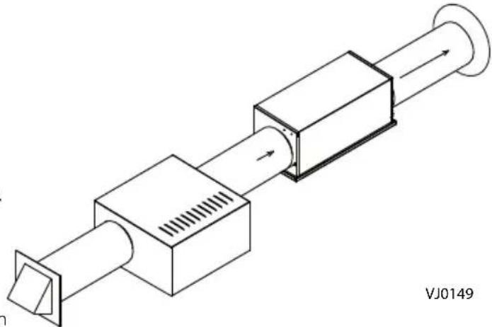
The installer shall ensure that, if necessary, an in-line heater sized according to required airflow and outside design heating temperature from Manual J or ASHRAE table is installed to avoid condensation on uninsulated duct distribution systems within the house or surfaces near the distribution register. The in-line heater shall have an integrated airflow sensor and an over temperature sensor to prevent heating in no-flow or low-flow conditions.
When deciding if a preheater is required and whether it should be installed BEFORE or AFTER the supply fan, consider the following:
- This supply fan's minimum operating temperature is 14 °F.
- The minimum distance between the preheater and the supply fan is 12 inches.
- The temperature distributed in the ducting should not be below 55 °F.
2.2.2 INSTALLATION WITH AN AHU
The installer shall ensure that, if necessary, an in-line heater sized according to required airflow
and outside design heating temperature from Manual J or ASHRAE table is installed to ensure that the air delivered to the AHU is never below the minimum temperature allowed by the manufacturer (generally 55°F). The in-line heater shall have an integrated airflow sensor and an over temperature sensor to prevent heating in no-flow or low-flow conditions.
When deciding if a preheater is required and whether it should be installed BEFORE or AFTER the supply fan, consider the following:
- This supply fan's minimum operating temperature is 14 °F.
- The minimum distance between the preheater and the supply fan is 12 inches.
- The temperature distributed in the ducting should not be below 55 °F, unless the AHU blower is always running when the supply fan runs. Refer to section 4.2 for wiring configurations.
natural_image
Technical line drawing of a mechanical assembly with ports and components, no visible text or symbols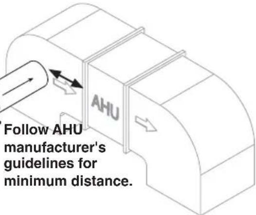
CAUTION
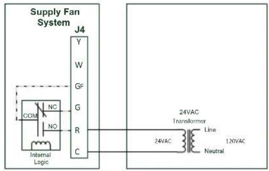
This unit has to be provided with a low voltage power source (AHU or other), refer to section 5.2 for wiring.
- Remove the unit from the box and inspect for damage. Installation hardware is located in a plastic bag along with this guide, on top of the filler.
- Put the unit down on a protected surface.
- Open the unit's door and remove the filter to allow for more room to work in the electronic compartment.

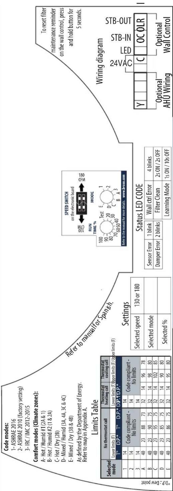
This unit reads temperature and relative humidity every hour and uses this data to choose the best time of the day to ventilate, according to the chosen mode's preset limits.
- Referring to the table below, choose the mode you want the unit to operate in and note it down in the space provided for that purpose on the unit's label.
| Selected mode* Climatic Zones** | |
| 1 - Ashrae 2016 | Zones 1-4 |
| 2 - Ashrae 2010 (factory setting) | Zones 1-4 |
| 3 - IRC / IMC 2012-2015 | Zones 1-4 |
| A - Comfort mode Hot / Humid #1 | Zones 2A and 1 |
| B - Comfort mode Hot / Humid #2 | Zones 1 and 2A |
| C - Comfort mode Hot / Dry | Zone 2B |
| D - Comfort mode Mixed / Humid | Zones 3A, 4A, 3C and 4C |
| E - Comfort mode Mixed / Dry | Zones 3B and 4B |
*Refer to the label on the inlet or to Appendix B for the full limits table.
**As defined by the Department of Energy. Refer to map in Appendix A.
-
Refer to your local building code to determine the required airflow.
-
Refer to the tables below. Find out what speed and run time percentage the unit has to be set in to provide the required airflow, and note down the chosen values in the space provided for that purpose on the unit's label.
For example: If the required airflow is 90 CFM (circled below), the speed switch should be set to 180 CFM, and the Run time % button, to 50%.
Run time % according to speed setting and required airflow
| Speed Setting | Required airflow (CFM) | |
| 30 35 40 45 50 55 60 65 70 75 80 85 90 95 100 105 | ||
| 130 CFM | 25 30 30 35 40 40 45 50 55 60 60 65 70 75 80 80 | |
| 180 CFM | 20 20 20 25 30 30 35 35 40 40 45 50 50 55 55 60 | |
| Run time % button value | ||
| Speed Setting | Required airflow (CFM) | |||||||||||||||
| 110 | 115 | 120 | 125 | 130 | 135 | 140 | 145 | 150 | 155 | 160 | 165 | 170 | 175 | 180 | ||
| 130 CFM | 85 | 90 | 90 | 95 | 100 | - | - | - | - | - | ||||||
| 180 CFM | 60 | 65 | 70 | 70 | 70 | 75 | 80 | 80 | 85 | 85 | 70 | 90 | 95 | 95 | 100 | |
| Run time % button value | ||||||||||||||||
Grayed out values are the recommended settings and should be preferred.
- Remove the screw holding the electronic compartment cover, as well as the cover itself.
- Set the Speed Switch to 130 CFM or 180 CFM, according to the settings chosen in step 6. The unit is factory set to 130 CFM.
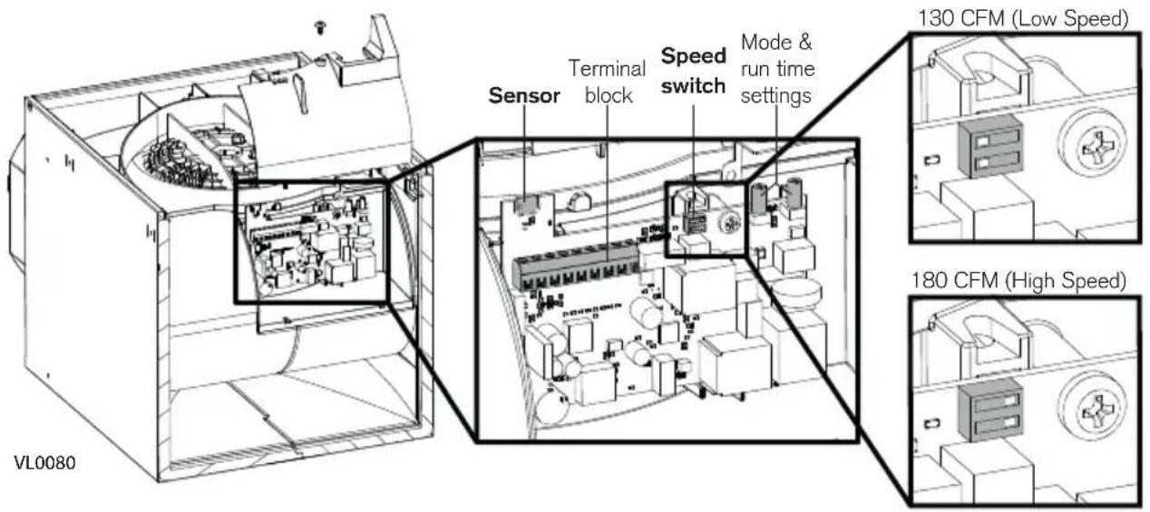
- Using the terminal block located on the electronic board, perform the low voltage connection; refer to Section 4.2 for the wiring diagrams. Connection to a low voltage power source is mandatory.
• Make sure that the polarity of the connections is respected.
- Pay special attention to the sensor located above the terminal block and the potentiometer buttons on the electronic board; they are very fragile, do not damage them while performing the connections.
- Run the low voltage wires along with the other wires all the way to the hole and grommet in the housing, where the low voltage wires should exit. Make sure that the wire seal foam is reinstalled.
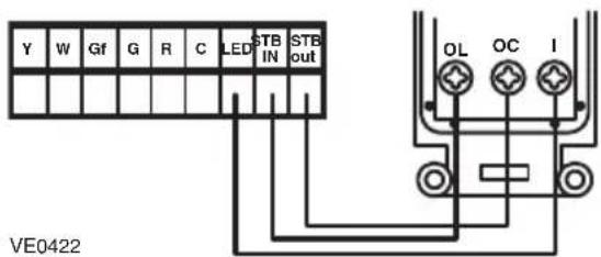
If the unit is to be connected to a VT11W optional wall control, the low voltage wire should be connected to the terminal block now. Refer to Section 4.3 for the wiring diagram.
CAUTION
Make sure that the wire seal foam is put back in place.
- Reinstall the electronic compartment cover (make sure not to pinch wires), and set the Mode and Run time % buttons according to the settings previously chosen.
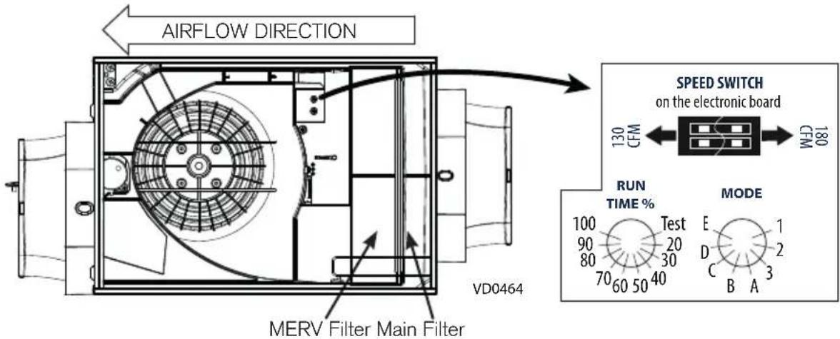
- Reinstall the main filter in the unit.
An optional MERV filter may be installed now. The main filter should remain as a prefilter, and the MERV filter should be installed as indicated above.
3.1 MOUNTING THE UNIT
When choosing a location for this unit, keep in mind that maintenance will have to be performed by the end user on a regular basis. Choose an easily accessible location and plan for a 14¼-in. clearance for the door to open.
For a 16-in. or 24-in. cc joists installation, use the optional bracket FIN-S1624 (see instructions packed with bracket).
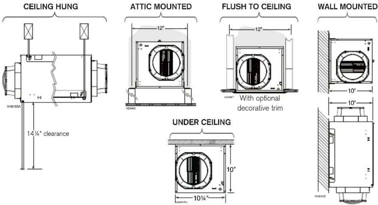
3.1.1 FLUSH-TO-CEILING
If the finishing will be done using the optional decorative finishing trim (part no. FIN-R1015), the springs included in the optional kit should be installed before installing the brackets.
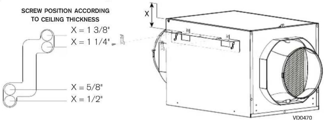
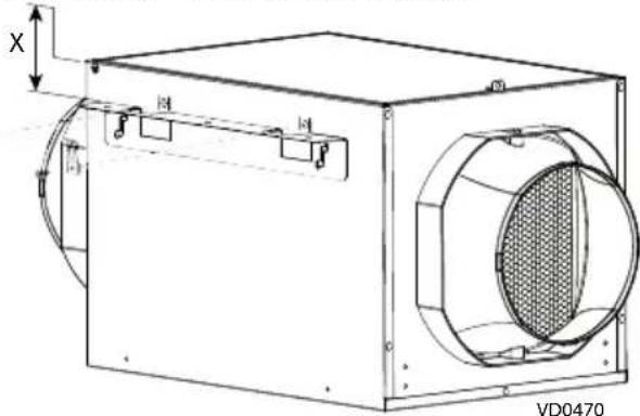
- Using 4 screws no. 8-18 x 0.375 in., install the brackets on the unit following the diagram below to adapt to the thickness of the ceiling. DO NOT USE OTHER SCREWS.
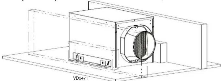
- Using 4 screws no. 10-12 x 0.625 in., install the unit between the joists. This unit is designed to fit between 12-in. cc joists. If the joists are closer, do not force the unit in, choose another installation method.
natural_image
Technical line drawing of a mechanical device with a circular component and labeled base (VD0471), no readable text or symbols beyond label.Prior to painting, clean the metal housing using solvent and the plastic decorative finishing trim using water.
3.1.2 UNDER CEILING OR WALL MOUNTED
-
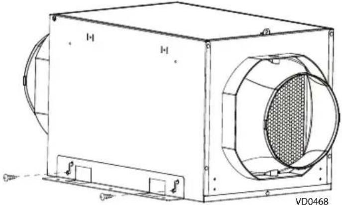
Using 4 screws no. 8-18 x 0.375 in., install the brackets on the unit as illustrated in Figure A. DO NOT USE OTHER SCREWS.
-
Using 4 screws no. 10-12 x 0.625 in. or longer screws if necessary, secure the unit to the wall or ceiling, into the studs, joists or other solid material.
When wall mounted, the unit can be positioned in any orientation to suit your need.
natural_image
Technical line drawing of a rectangular industrial device with a circular vent and side mounting brackets (no text or symbols)Figure A: Bracket installation
3.1.3 CEILING HUNG
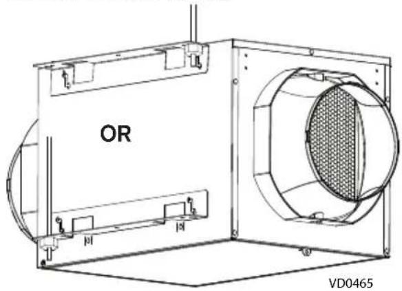
The brackets have been designed to allow that the unit be hung using threaded rods.
- Using 4 screws no. 8-18 x 0.375 in., install the brackets in one of both ways illustrated below. DO NOT USE OTHER SCREWS. Use nuts to secure the unit.
3.1.4 IN THE ATTIC
CAUTION
Do not install in an attic where the temperature may exceed 160 °F.
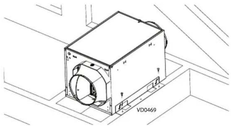
- Using 4 screws no. 8-18 x 0.375 in., install the brackets on the unit as illustrated above in Figure A. DO NOT USE OTHER SCREWS.
- Using 4 screws no. 10-12 x 0.625 in., secure the unit to the joists or cross framing.
natural_image
Technical line drawing of a mechanical device labeled VD0469, showing internal components and mounting brackets (no readable text beyond label)3.2 CONNECTING THE INSULATED DUCTS TO THE UNIT
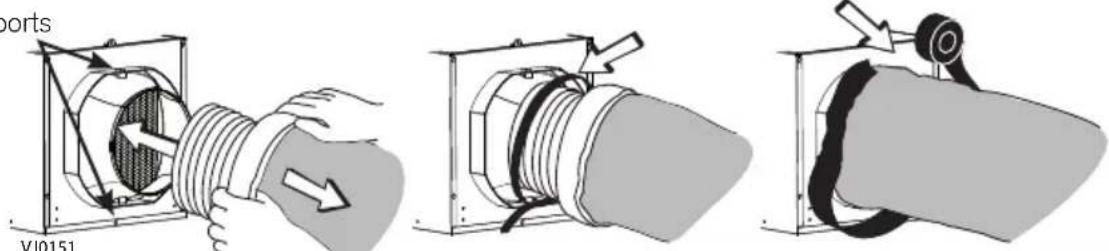
- Slide the inner 6 in. round flexible duct over the port and tie it using a tie-wrap.
- Pull the insulation over the inner ring of the port without compressing it to minimize possible condensation buildup within the duct, as well as minimize building heat loss and gain.
- Use duct tape to seal the outer membrane of the insulated duct to the outer ring of the port to create an air-tight path and to minimize building heat loss and gain and reduce the potential for condensation.

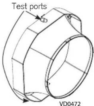
Avoid blocking the test ports with the duct tape.
Test ports
CAUTION
Make sure to replace insulation around any openings made in the building envelope when installing unit or ducting. Seal insulation with tape or caulk to minimize building heat loss and gain and to reduce the potential for condensation.
WARNING
Make sure the outdoor intake hood is at least 12 inches above the ground and 6 feet away from any of the following: Dryer exhaust, high-efficiency furnace vent, central vacuum vent, gas meter exhaust, gas barbecue-grill, any exhaust from a combustion source, garbage bin and any other source of contamination.
Make sure that the outdoor intake hood is easily accessible for annual maintenance. If located above the first floor, place it close to a window or balcony to allow ease of access.
IMPORTANT - The ducting from this fan to the outside of the building has a strong effect on the air flow, noise and energy use of the fan. Use the shortest, straightest duct routing possible for best performance, and avoid installing the fan with smaller ducts than recommended. Insulation around the ducts can reduce energy loss and inhibit mold growth. Fans installed with existing ducts may not achieve their rated airflow.
3.3 CONNECT POWER
3.3.1 FIN-180P
Plug the unit power cord into a mating 3-prong grounding receptacle.
3.3.2 FIN-180P-HW
⚠ WARNING
Risk of electric shock. Electrical wiring must be done by qualified personnel in accordance with all applicable codes and standards. Before connecting wires, switch power off at service panel and lock service disconnecting means to prevent power from being switched on accidentally.
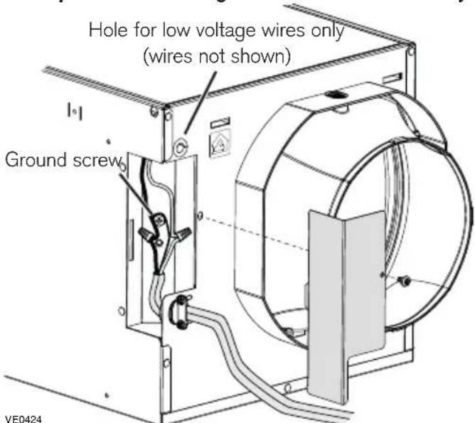
NOTE: The insulated duct and the low voltage wires not shown to simplify the illustration.
- Detach the electrical compartment cover from the unit by removing its retaining screw.
-
Install the included wire clamp on the unit. Insert the house wiring cable through the wire clamp and tighten the wire clamp to secure the cable.
-
Using provided wire connectors, connect wires as follows: BLACK to BLACK, WHITE to WHITE and GREEN or BARE wire under ground screw. DO NOT FORGET TO CONNECT THE GROUND.
-
Put back in place the electrical compartment cover, taking care not to pinch wires. Restore power to the unit.
⚠ WARNING
Risk of electric shock. Electrical wiring must be done by qualified personnel in accordance with all applicable codes and standards. Before connecting wires, switch power off at service panel and lock service disconnecting means to prevent power from being switched on accidentally.
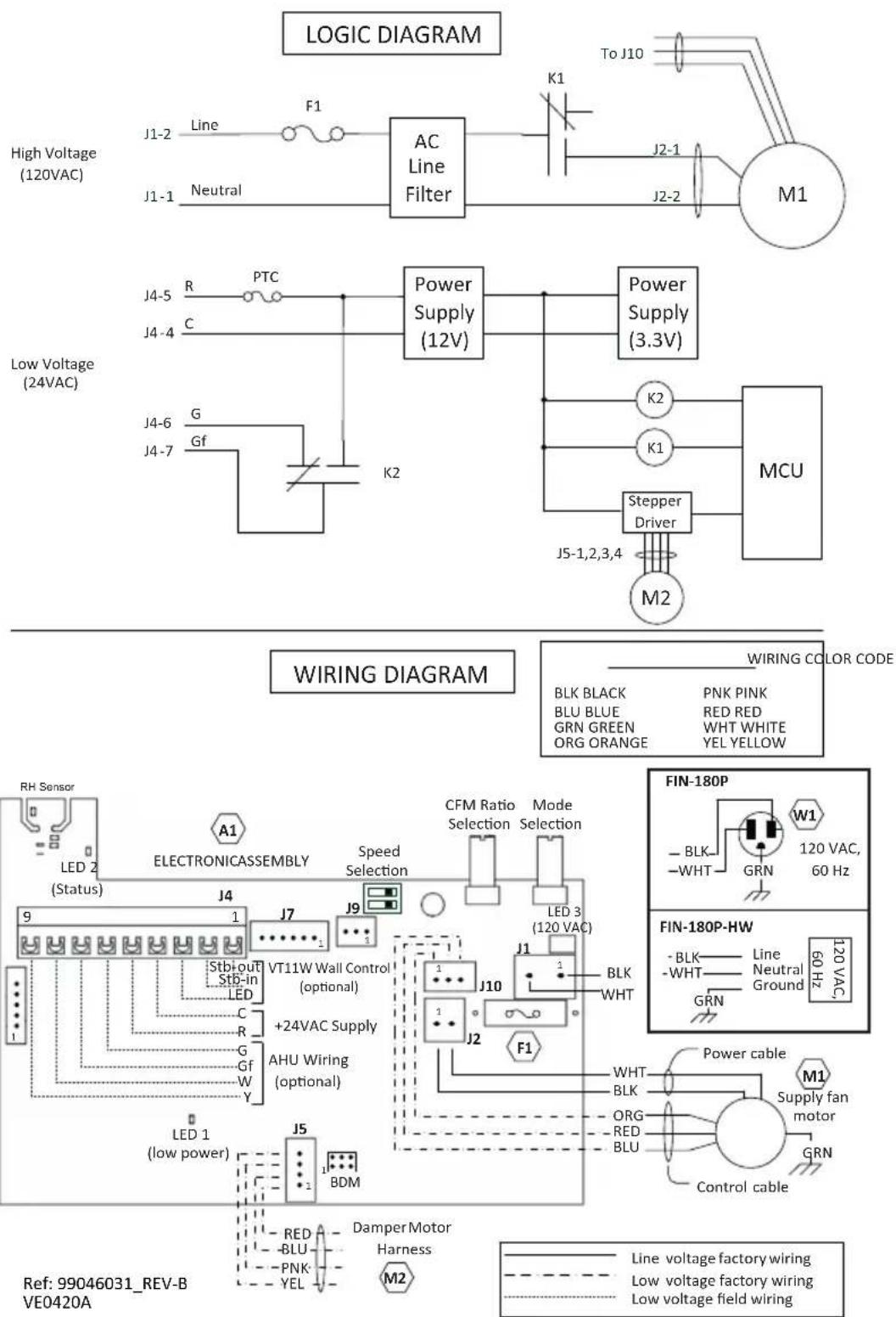
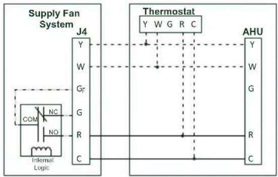
4.1 WIRING AND LOGIC DIAGRAMS
4.2 CONNECTION TO THE AHU
WARNING
Risk of electric shock. Electrical wiring must be done by qualified personnel in accordance with all applicable codes and standards. Before connecting wires, switch power off at service panel and lock service disconnecting means to prevent power from being switched on accidentally.
CAUTION
Control interface of AHU systems may vary. Please contact your AHU supplier for any installation involving alternate wiring electrical specifications.
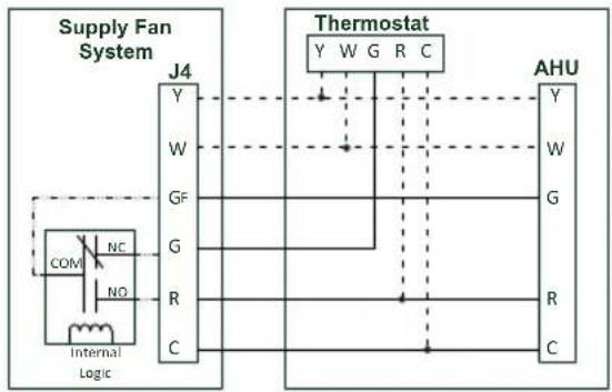
Start AHU blower when supply fan is running
flowchart
graph TD
    subgraph Supply Fan System
        J4["J4"] --> Y["Y"]
        J4 --> W["W"]
        J4 --> GF["GF"]
        J4 --> G["G"]
        J4 --> R["R"]
        J4 --> C["C"]
    end

    subgraph Thermostat
        Y --> YW["W"]
        YW --> GG["G"]
        YW --> R["R"]
        YW --> C["C"]
    end

    J4 -->|COM| NC["NC"]
    J4 -->|NO| NO["NO"]
    J4 -->|Internal Logic| InternalLogic
    Y -->|Thermostat| AHU["AHU"]
    W --> AHU
    GF --> AHU
    G --> AHU
    R --> AHU
    C --> AHU
    AHU --> Y
    AHU --> W
    AHU --> G
    AHU --> R
    AHU --> C
No AHU connection, stand alone supply
flowchart
graph TD
    A["Supply Fan System J4"] -->|Y| B["Internal Logic"]
    A -->|W| C["24VAC Transformer"]
    A -->|GF| D["Line"]
    A -->|G| E["Neutral"]
    A -->|R| F["Line"]
    A -->|C| G["Line"]
    H["COM"] -->|NC| I["Internal Logic"]
    I --> A
    style A fill:#f9f,stroke:#333
    style B fill:#ccf,stroke:#333
    style C fill:#ccf,stroke:#333
    style D fill:#ccf,stroke:#333
    style E fill:#ccf,stroke:#333
    style F fill:#ccf,stroke:#333
    style G fill:#ccf,stroke:#333
    style H fill:#fff,stroke:#000
    style I fill:#fff,stroke:#000
    style_J["24VAC Transformer"] --> K["Line"]
    K --> L["120VAC"]
AHU blower not activated when supply fan is running
flowchart
graph TD
    subgraph Supply Fan System
        J4["J4"] --> Y["Y"]
        J4 --> W["W"]
        J4 --> Gf["Gf"]
        J4 --> G["G"]
        J4 --> R["R"]
        J4 --> C["C"]
    end

    subgraph Thermostat
        YW["W"] --> GRC["G"]
        AHU["Y"] --> R["R"]
        AHU --> C["C"]
    end

    style Supply Fan System fill:#f9f,stroke:#333
    style Thermostat fill:#ccf,stroke:#333
Mandatory Installation Wiring
— — Supply Fan Internal Hard Connections
— — — — Optional Installation Wiring for Synchronization
Synchronize the Supply Fan operation with the heating and cooling run-time to prevent unnecessary central fan operating time (refer to the dotted lines in the above diagram).
VE0484A
4.3 CONNECTION TO THE VT11W OPTIONAL WALL CONTROL
5. HOW TO TEST THE UNIT
After the unit has been installed, the low voltage connection has been made, and the ducts and hoods have been installed, the airflow can be tested. To do so:
- Open the unit's door and take note of the unit's Run time % setting.
- If connected to the ducting of an AHU, turn the AHU OFF while measuring the airflow.
- Turn the Run time % button in the "Test" position and close the door.
- Wait until the booting sequence is done (at least 45 seconds).
- Remove the test port cap located on the port on the intake side of the unit (closest to the filter).
-
Test the airflow using a Pitot tube. The distance between the test port and the center of the duct is 3.75 inches.
-
Put the cap back on the test port.
-
Set the Run time % button back to its previous setting.
NOTE: To force the damper closing, unplug the power cord or turn power off at service panel. The low voltage (24VAC) must remain connected to allow damper operation.
6. SERVICE PARTS
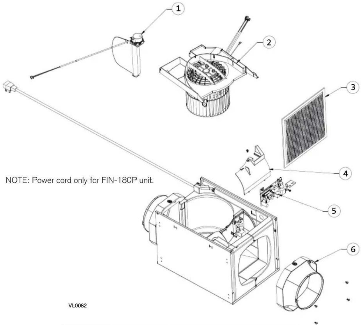
| Item no. | Part no. | Description |
| 1 | S970 | 21043 Damper Assembly |
| 2 | S970 | 21044 Motor Assembly |
| 3 | S970 | 21045 Main Filter |
| 4 | S970 | 21048 Electronic Cover |
| 5 | S970 | 21047 Electronic Board |
| 6 | S970 | 21041 6-in. Port |
| Not shown | FIN-S1624 | Optional Bracket |
| Not shown | VT11W | Optional Wall Control |
| Not shown | FIN-R1015 | Optional Decorative Trim |
| Not shown | 99010461 | Optional MERV 8 Filter |
| Not shown | 99010462 | Optional MERV13 Filter |
Replacement Parts and Repair
In order to ensure your ventilation unit remains in good working condition, you must use Broan-NuTone LLC genuine replacement parts only. The Broan-NuTone LLC genuine replacement parts are specially designed for each unit and are manufactured to comply with all the applicable certification standards and maintain a high standard of safety. Any third party replacement part used may cause serious damage and drastically reduce the performance level of your unit, which will result in premature failing. Also, Broan-NuTone LLC recommends to contact a Broan-NuTone LLC certified service depot for all replacement parts and repairs.
WARNING
Risk of electric shock. Before performing any maintenance or servicing, always disconnect the unit from its power source or turn power off at service panel. Some troubleshooting steps (boxes in light grey) require the unit to be powered while being manipulated; beware of live and moving parts at all times.
7.1 FIN-180P TROUBLESHOOT
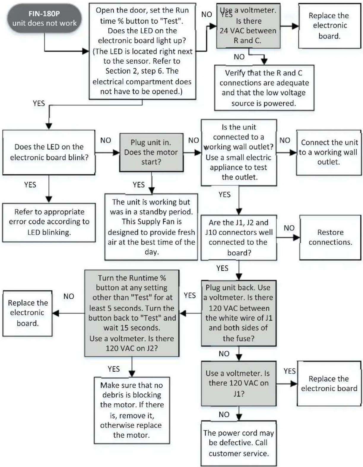
flowchart
graph TD
    A["FIN-180P unit does not work"] --> B["Open the door, set the Run time % button to "Test". Does the LED on the electronic board light up? (The LED is located right next to the sensor. Refer to Section 2, step 6. The electrical compartment does not have to be opened)."]
    B --> C{Does the LED on the electronic board blink?}
    C -->|YES| D["Refer to appropriate error code according to LED blinking"]
    C -->|NO| E["Plug unit in. Does the motor start?"]
    E --> F{The unit is working but was in a standby period. This Supply Fan is designed to provide fresh air at the best time of the day.}
    F -->|YES| G["Is the unit connected to a working wall outlet? Use a small electric appliance to test the outlet."]
    F -->|NO| H{Are the J1, J2 and J10 connectors well connected to the board?}
    H -->|YES| I["Replace the electronic board."]
    H -->|NO| J["Connect the unit to a working wall outlet."]
    E -->|NO| K["Use a voltmeter. Is there 24 VAC between R and C."]
    K --> L["Replace the electronic board."]
    E -->|YES| M["Make sure that no debris is blocking the motor. If there is, remove it, otherwise replace the motor."]
    M --> N{Turn the runtime % button at any setting other than "Test" for at least 5 seconds. Turn the button back to "Test" and wait 15 seconds. Use a voltmeter. Is there 120 VAC on J2?}
    N -->|YES| O["Use a voltmeter. Is there 120 VAC on J1?"]
    O --> P{Use a voltmeter. Is there 120 VAC on J1?}
    P -->|NO| Q["Replace the electronic board"]
    P -->|YES| R["The power cord may be defective. Call customer service."]
⚠ WARNING
Risk of electric shock. Before performing any maintenance or servicing, always disconnect the unit from its power source or turn power off at service panel. Some troubleshooting steps (boxes in light grey) require the unit to be powered while being manipulated; beware of live and moving parts at all times.
7.2 FIN-180P-HW TROUBLESHOOT
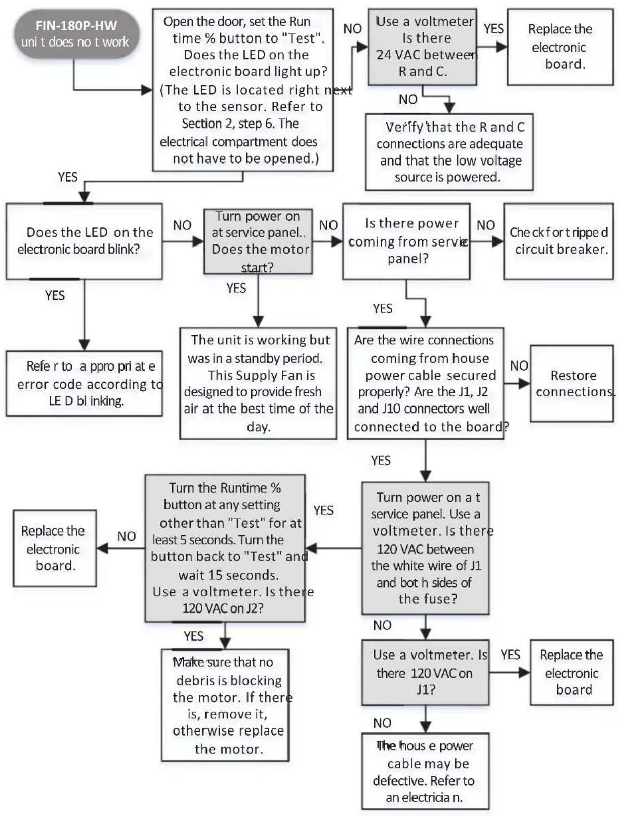
flowchart
graph TD
    A["FIN-180P-HW uni t does not work"] --> B["Open the door, set the Run time % button to "Test". Does the LED on the electronic board light up? (The LED is located right next to the sensor. Refer to Section 2, step 6. The electrical compartment does not have to be opened.)"]
    B --> C{Does the LED on the electronic board blink?}
    C -->|YES| D["Turn power on at service panel.. Does the motor start?"]
    C -->|NO| E["Use a voltmeter Is there 24 VAC between R and C."]
    E -->|YES| F["Replace the electronic board."]
    E -->|NO| G["Verify that the R and C connections are adequate and that the low voltage source is powered."]
    G --> H{Is there power coming from service panel?}
    H -->|YES| I["Are the wire connections coming from house power cable secured properly? Are the J1, J2 and J10 connectors well connected to the board?"]
    H -->|NO| J["Check for tripped circuit breaker."]
    I --> K{Are the wire connections coming from house power cable secured properly? Are the J1, J2 and J10 connectors well connected to the board?}
    K -->|YES| L["Restore connections."]
    K -->|NO| M["Turn power on a t service panel. Use a voltmeter. Is there 120 VAC between the white wire of J1 and both sides of the fuse?"]
    L --> N{Turn the runtime % button at any setting other than "Test" for at least 5 seconds. Turn the button back to "Test" and wait 15 seconds. Use a voltmeter. Is there 120 VAC on J2?}
    N -->|YES| O["Make sure that no debris is blocking the motor. If there is, remove it, otherwise replace the motor."]
    O --> P{Turn the runtime % button at any setting other than "Test" for at least 5 seconds. Turn the button back to "Test" and wait 15 seconds. Use a voltmeter. Is there 120 VAC on J2?}
    P -->|NO| Q["Replace the electronic board."]
    P -->|YES| R["Use a voltmeter. Is there 120 VAC on J1?"]
    R -->|YES| S["Replace the electronic board"]
    R -->|NO| T["The house e power cable may be defective. Refer to an electricia n."]
7.3 ALL UNITS TROUBLESHOOT
| LED Blinking Codes | |
| Sensor Error 1 blink | |
| Damper Error 2 blinks | |
| Wall Control Error 4 blinks | |
| Filter Maintenance | Slow blink(2 s ON, 2 s OFF) |
| Learning Mode | Very slow blink(1 s ON, 10 s OFF) |
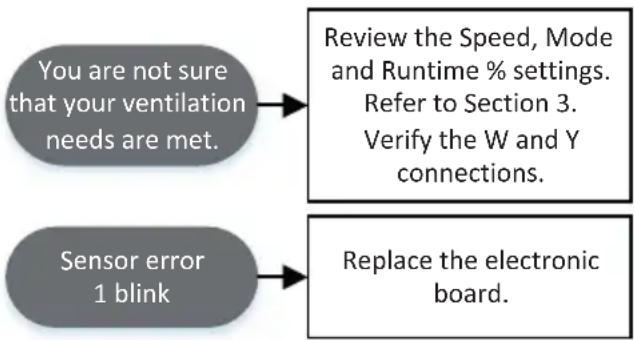
flowchart
graph TD
    A["You are not sure that your ventilation needs are met."] --> B["Review the Speed, Mode and Runtime % settings. Refer to Section 3. Verify the W and Y connections."]
    C["Sensor error 1 blink"] --> D["Replace the electronic board."]
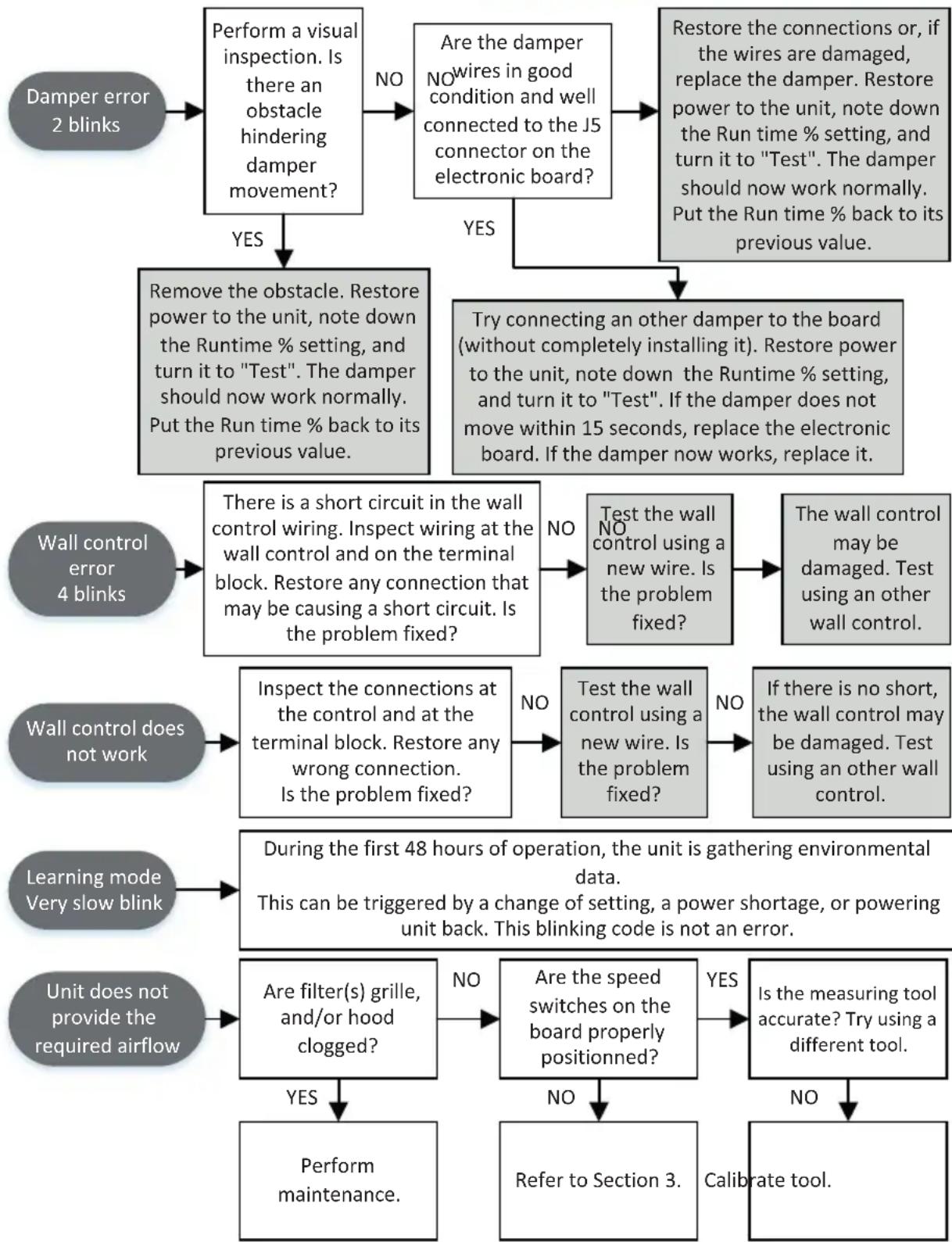
flowchart
graph TD
    A["Damper error 2 blinks"] --> B["Perform a visual inspection. Is there an obstacle hindering damper movement?"]
    B -->|NO| C["Are the damper wires in good condition and well connected to the J5 connector on the electronic board?"]
    C -->|YES| D["Restore the connections or, if the wires are damaged, replace the damper. Restore power to the unit, note down the Run time % setting, and turn it to "Test". The damper should now work normally. Put the Run time % back to its previous value."]
    C --> E["Try connecting an other damper to the board (without completely installing it). Restore power to the unit, note down the Runtime % setting, and turn it to "Test". If the damper does not move within 15 seconds, replace the electronic board. If the damper now works, replace it."]
    B --> F["Remove the obstacle. Restore power to the unit, note down the Runtime % setting, and turn it to "Test". The damper should now work normally. Put the Run time % back to its previous value."]
    F --> G["Wall control error 4 blinks"]
    G --> H["There is a short circuit in the wall control wiring. Inspect wiring at the wall control and on the terminal block. Restore any connection that may be causing a short circuit. Is the problem fixed?"]
    H -->|NO| I["Test the wall NO control using a new wire. Is the problem fixed?"]
    I --> J["The wall control may be damaged. Test using an other wall control."]
    G --> K["Inspect the connections at the control and at the terminal block. Restore any wrong connection. Is the problem fixed?"]
    K -->|NO| L["Test the wall control using a new wire. Is the problem fixed?"]
    L -->|NO| M["If there is no short, the wall control may be damaged. Test using an other wall control."]
    K --> N["During the first 48 hours of operation, the unit is gathering environmental data. This can be triggered by a change of setting, a power shortage, or powering unit back. This blinking code is not an error."]
    N --> O["Learning mode Very slow blink"]
    O --> P["Unit does not provide the required airflow"]
    P --> Q["Are filter(s) grille, and/or hood clogged?"]
    Q -->|NO| R["Are the speed switches on the board properly positioned?"]
    R -->|YES| S["Is the measuring tool accurate? Try using a different tool."]
    R -->|NO| T["Refer to Section 3."]
    T --> U["Calibrate tool."]
    Q --> V["Perform maintenance."]
    V --> W["Unit does not provide the required airflow"]
8. WARRANTY
Warranty Period and Exclusions: Broan-NuTone LLC (the "Company") warrants to the original consumer purchaser of its product ("you") that the product (the "Product") will be free from material defects in the Product or its workmanship for five (5) years, starting on the date you purchase the Product.
The limited warranty period for any replacement parts provided by the Company and for any Products repaired or replaced under this limited warranty shall be the remainder of the original warranty period.
This warranty does not cover fluorescent lamp starters, tubes, halogen and incandescent bulbs, fuses, filters, ducts, roof caps, wall caps and other accessories for ducting that may be purchased separately and installed with the Product. This warranty also does not cover (a) normal maintenance and service, (b) normal wear and tear, (c) any Products or parts which have been subject to misuse, abuse, abnormal usage, negligence, accident, improper or insufficient maintenance, storage or repair (other than repair by the Company), (d) damage caused by faulty installation, or installation or use contrary to the recommendations or instructions of the Company or its representatives, (e) any Product that has been moved from its original point of installation, (f) damage caused by environmental or natural elements, (g) damage in transit, (h) natural wear of finish, (i) Products in commercial or nonresidential use, (j) damage caused by fire, flood or other act of God, (k) consumable parts, (l) cosmetic damage, including but not limited to scratches or dents, or (m) Products with altered, defaced or removed serial numbers. This warranty covers only Products sold to original consumers in the United States and Canada by the Company or its U.S. and Canadian distributors authorized by the Company.
This warranty supersedes all prior warranties and, subject to applicable law, is not transferable from the original consumer purchaser.
No Other Warranties: To the maximum extent permitted by applicable law, this limited warranty contains the Company's sole obligation and your sole remedy for defective products. The foregoing warranties are exclusive and in lieu of any other warranties and conditions, express or implied. THE COMPANY DISCLAIMS AND EXCLUDES ALL OTHER EXPRESS WARRANTIES AND CONDITIONS, AND DISCLAIMS AND EXCLUDES ALL WARRANTIES AND CONDITIONS IMPLIED BY LAW, INCLUDING WITHOUT LIMITATION THOSE OF MERCHANTABILITY AND FITNESS FOR A PARTICULAR PURPOSE. To the extent that applicable law prohibits the exclusion of implied warranties or conditions, the duration of any applicable implied warranty or condition is limited to the period specified for the express warranty above. Some jurisdictions do not allow limitations on how long an implied warranty lasts, so the above limitation may not apply to you. Any oral or written description of the Product is for the sole purpose of identifying it and shall not be construed as an express warranty.
Whenever possible, each provision of this Limited Warranty shall be interpreted in such manner as to be effective and valid under applicable law, but if any provision is held to be prohibited or invalid, such provision shall be ineffective only to the extent of such prohibition or invalidity, without invalidating the remainder of such provision or the other remaining provisions of the Limited Warranty.
Remedy: During the limited warranty period as stated above, the Company will, at its option, provide replacement parts for, or repair or replace, without charge, any Product or part thereof, to the extent the Company finds it to be covered by and in breach of this limited warranty under normal use and service. The Company will ship the repaired or replaced Product or replacement parts to you in the United States or Canada at no charge. You are responsible for all costs for removal, reinstallation and shipping, insurance or other freight charges incurred in the shipment of the Product or part to the Company. If you must send the Product or part to the Company, as instructed by the Company, you must properly pack the Product or part—the Company is not responsible for damage in transit. The Company reserves the right to utilize reconditioned, refurbished, repaired or remanufactured Products or parts in the warranty repair or replacement process. Such Products and parts will be comparable in function and performance to an original Product or part and warranted for the remainder of the original warranty period.
The Company reserves the right, in its sole discretion, to refund the money actually paid by you for the Product in lieu of repair or replacement. If the Product or part is no longer available, replacement may be made with a similar product of equal or greater value, at the Company's sole discretion.
Exclusion of Damages: THE COMPANY'S OBLIGATION TO PROVIDE REPLACEMENT PARTS, OR REPAIR, REPLACE OR REFUND, AT THE COMPANY'S OPTION, SHALL BE YOUR SOLE AND EXCLUSIVE REMEDY UNDER THIS LIMITED WARRANTY AND THE COMPANY'S SOLE AND EXCLUSIVE OBLIGATION. TO THE EXTENT PERMITTED BY THE APPLICABLE LAW, THE COMPANY SHALL NOT BE LIABLE FOR INCIDENTAL, INDIRECT, CONSEQUENTIAL OR SPECIAL DAMAGES ARISING OUT OF OR IN CONNECTION WITH THE PRODUCT, ITS USE OR PERFORMANCE. Incidental damages include, but are not limited to, such damages as loss of time and loss of use. Consequential damages include, but are not limited to, the cost of repairing or replacing other property which is damaged if the Product does not work properly.
TO THE EXTENT PERMITTED BY THE APPLICABLE LAW, THE COMPANY SHALL NOT BE LIABLE TO YOU, OR TO ANYONE CLAIMING UNDER YOU, FOR ANY OTHER OBLIGATIONS OR LIABILITIES, INCLUDING, BUT NOT LIMITED TO, OBLIGATIONS OR LIABILITIES ARISING OUT OF BREACH OF CONTRACT OR WARRANTY, NEGLIGENCE OR OTHER TORT OR ANY THEORY OF STRICT LIABILITY, WITH RESPECT TO THE PRODUCT OR THE COMPANY'S ACTS OR OMISSIONS OR OTHERWISE.
Some jurisdictions do not allow the exclusion or limitation of incidental or consequential damages, so the above limitation or exclusion may not apply to you. This warranty gives you specific legal rights, and you may also have other rights, which vary from jurisdiction to jurisdiction. The disclaimers, exclusions, and limitations of liability under this warranty will not apply to the extent prohibited by applicable law.
This warranty covers only replacement or repair of defective Products or parts thereof at the Company's main facility, or such other facility as Company may designate from time to time, and does not include the cost of field service travel and living expenses, which expenses shall be disclosed to and accepted by you in advance.
Any assistance the Company provides to or procures for you outside the terms, limitations or exclusions of this limited warranty will not constitute a waiver of such terms, limitations or exclusions, nor will such assistance extend or revive the warranty.
The Company will not reimburse you for any expenses incurred by you in repairing or replacing any defective Product, except for those incurred with the Company's prior written permission.
How to Obtain Warranty Service: To qualify for warranty service, you must (a) notify the Company at the address or telephone number stated below within seven (7) days of discovering the covered defect, (b) give the model number and part identification, and (c) describe the nature of any defect in the Product or part. At the time of requesting warranty service, you must present evidence of the original purchase date. If you cannot provide a copy of the original written limited warranty, then the terms of the Company's most current written limited warranty for your particular product will control. The most current limited written warranties for the Company's products can be found at www.broan.com.
Broan-NuTone LLC, 926 West State Street, Hartford, WI 53027 800.558.1711
9. APPENDIX A
geo
| Zone | Color | |---|---| | 1 | Red | | 2A | Orange | | 2B | Dark Red | | 3A | Orange to Red | | 3B | Orange to Red | | 3C | Orange to Red | | 4A | Yellow to Green | | 4B | Yellow to Green | | 4C | Yellow to Green | | 5A | Light Blue to Green | | 5B | Light Blue to Green | | 6A | Light Blue to Green | | 6B | Light Blue to Green | | 7A | Light Blue to Green | | 7B | Light Blue to Green | | 8A | Light Blue to Green | | 8B | Light Blue to Green | | 9A | Light Blue to Green | | 9B | Light Blue to Green | | 10A | Light Blue to Green | | 10B | Light Blue to Green | | 11A | Light Blue to Green | | 11B | Light Blue to Green | | 12A | Light Blue to Green | | 12B | Light Blue to Green | | 13A | Light Blue to Green | | 13B | Light Blue to Green | | 14A | Light Blue to Green | | 14B | Light Blue to Green | | 15A | Light Blue to Green | | 15B | Light Blue to Green | | 16A | Light Blue to Green | | 16B | Light Blue to Green | | 17A | Light Blue to Green | | 17B | Light Blue to Green | | 18A | Light Blue to Green | | 18B | Light Blue to Green | | 19A | Light Blue to Green | | 19B | Light Blue to Green | | 20A | Light Blue to Green | | 20B | Light Blue to Green | | 21A | Light Blue to Green | | 21B | Light Blue to Green | | 22A | Light Blue to Green | | 22B | Dark Red | | 23A | Orange to Red | | 23B | Orange to Red | | 24A | Orange to Red | | 24B | Orange to Red | | 25A | Orange to Red | | 25B | Orange to Red | | 26A | Orange to Red | | 26B | Orange to Red | | 27A | Orange to Red | | 27B | Orange to Red | | 28A | Orange to Red | | 28B | Orange to Red | | 29A | Orange to Red | | 29B | Orange to Red | | 30A | Orange to Red | | 30B | Orange to Red | | 31A | Orange to Red | | 31B | Orange to Red | | 32A | Orange to Red | | 32B | Orange to Red | | 33A | Orange to Red | | 33B | Orange to Red | | 34A | Orange to Red | | 34B | Orange to Red | | 35A | Orange to Red | | 35B | Orange to Red | | 36A | Orange to Red | | 36B | Orange to Red | | 37A | Orange to Red | | 37B | Orange to Red | | 38A | Orange to Red | | 38B | Orange to Red | | 39A | Orange to Red | | 39B | Orange to Red | | 40A | Orange to Red | | 40B | Orange to Red | | 41A | Orange to Red | | 41B | Orange to Red | | 42A | Orange to Red | | 42B | Orange to Red | | 43A | Orange to Red | | 43B | Orange to Red | | 44A | Orange to Red | | 44B | Orange to Red | | 45A | Orange to Red | | 45B | Orange to Red | | 46A | Orange to Red | | 46B | Orange to Red | | 47A | Orange to Red | | 47B | Orange to Red | | 48A | Orange to Red | | 48B | Orange to Red | | 49A | Orange to Red | | 49B | Orange to Red | | 50A | Orange to Red | | 50B | Orange to Red | | 51A | Orange to Red | | 51B | Orange to Red | | 52A | Orange to Red | | 52B | Orange to Red | | 53A | Orange to Red | | 53B | Orange to Red | | 54A | Orange to Red | | 54B | Orange to Red | | 55A | Orange to Red | | 55B | Orange to Red | | 56A | Orange to Red | | 56B | Orange to Red | | 57A | Orange to Red | | 57B | Orange to Red | | 58A | Orange to Red | | 58B | Orange to Red | | 59A | Orange to Red | | 59B | Orange to Red | | 60A | Orange to Red | | 60B | Orange to Red | | 61A | Orange to Red | | 61B | Orange to Red | | 62A | Orange to Red | | 62B | Orange to Red | | 63A | Orange to Red | | 63B | Orange to Red | | 64A | Orange to Red | | 64B | Orange to Red | | 65A | Orange to Red | | 65B | Orange to Red | | 66A | Orange to Red | | 66B | Orange to Red | | 67A | Orange to Red | | 67B | Orange to Red | | 68A | Orange to Red | | 68B | Orange to Red | | 69A | Orange to Red | | 69B | Orange to Red | | 70A | Orange to Red | | 70B | Orange to Red | | 71A | Orange to Red | | 71B | Orange to Red | | 72A | Orange to Red | | 72B | Orange to Red | | 73A | Orange to Red | | 73B | Orange to Red | | 74A | Orange to Red | | 74B | Orange to Red | | 75A | Orange to Red | | 75B | Orange to Red | | 76A | Orange to Red | | 76B | Orange to Red | | 77A | Orange to Red | | 77B | Orange to Red | | 78A | Orange to Red | | 78B | Orange to Red | | 79A | Orange to Red | | 79B | Orange to Red | | 80A | Orange to Red | | 80B | Orange to Red | | 81A | Orange to Red | | 81B | Orange to Red | | 82A | Orange to Red | | 82B | Orange to Red | | 83A | Orange to Red | | 83B | Orange to Red | | 84A | Orange to Red | | 84B | Orange to Red | | 85A | Orange to Red | | 85B | Orange to Red | | 86A | Orange to Red | | 86B | Orange to Red | | 87A | Orange to Red | | 87B | Orange to Red | | 88A | Orange to Red | | 88B | Orange to Red | | 89A | Orange to Red | | 89B | Orange to Red | | 90A | Orange to Red | | 90B | Orange to Red | | 91A | Orange to Red | | 91B | Orange to Red | | 92A | Orange to Red | | 92B | Orange to Red | | 93A | Orange to Red | | 93B | Orange to Red | | 94A | Orange to Red | | 94B | Orange to Red | | 95A | Orange to Red | | 95B | Orange to Red | | 96A | Orange to Red | | 96B | Orange to Red | | 97A | Orange to Red | | 97B | Orange to Red | | 98A | Orange to Red | | 98B | Orange to Red | | 99A | Orange to Red | | 99B | Orange to Red | | (incl. Hawaii)*Not recommended in all other zones
| Selected mode Climatic | Zones* |
| 1 - Ashrae 2016 | Zones 1-4 |
| 2 - Ashrae 2010 (factory setting) | Zones 1-4 |
| 3 - IRC / IMC 2012-2015 | Zones 1-4 |
| A - Comfort mode Hot / Humid #1 | Zones 2A and 1 |
| B - Comfort mode Hot / Humid #2 | Zones 1 and 2A |
| C - Comfort mode Hot / Dry | Zone 2B |
| D - Comfort mode Mixed / Humid | Zones 3A, 4A, 3C and 4C |
| E - Comfort mode Mixed / Dry | Zones 3B and 4B |
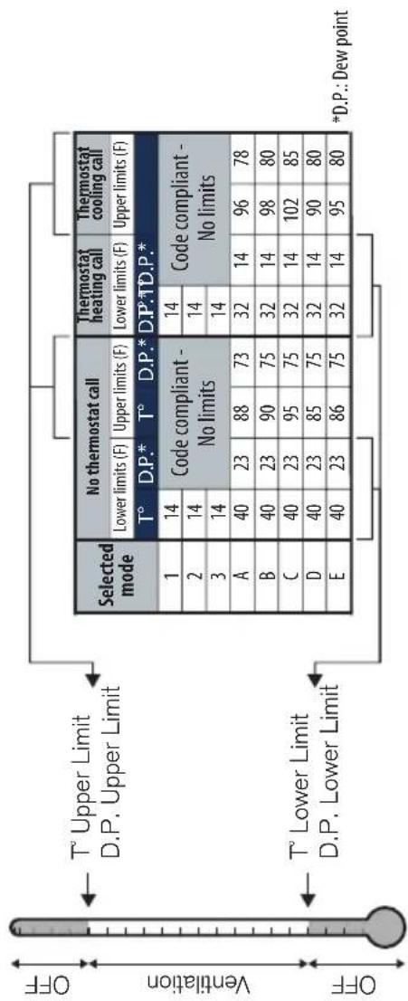
flowchart
graph TD
    A["Selected mode"] --> B{No thermostat cell}
    B --> C["Thermostat cooling cell"]
    C --> D{Code compliant - No limits}
    D --> E["Code compliant - 14"]
    D --> F["Code compliant - 14"]
    D --> G["Code compliant - 14"]
    E --> H["1 / 14"]
    F --> I["2 / 14"]
    G --> J["3 / 14"]
    H --> K["A / 40"]
    I --> L["B / 40"]
    J --> M["C / 40"]
    K --> N["D / 40"]
    L --> O["D / 40"]
    M --> P["E / 40"]
    N --> Q["E / 40"]
    O --> R["E / 40"]
    P --> S["E / 40"]
    Q --> T["E / 40"]
    R --> U["E / 40"]
    S --> V["E / 40"]
    T --> W["E / 40"]
    U --> X["E / 40"]
    V --> Y["E / 40"]
    W --> Z["E / 40"]
    X --> AA["E / 40"]
    Y --> AB["E / 40"]
    Z --> AC["E / 40"]
    AA --> AD["E / 40"]
    AB --> AE["E / 40"]
    AC --> AF["E / 40"]
    AD --> AG["E / 40"]
    AE --> AH["E / 40"]
    AF --> AI["E / 40"]
    AG --> AJ["E / 40"]
    AH --> AK["E / 40"]
    AI --> AL["E / 40"]
flowchart
Air conditioning system control flowchart covering code mode selection, status LED code settings, and limit table configuration.Fresh in Premium
BROAN®
FRESH IN™ PREMIUM
FIN-180P y FIN-180P-HW
natural_image
Technical line drawing of a mechanical device with a cylindrical component and connecting rod (no text or symbols)FIN-180P
natural_image
Technical line drawing of a mechanical device with cylindrical and rectangular components (no text or symbols)FIN-180P-HW
CABLEADO
VB0260
REGISTRE SU PRODUCTO EN LÍNEA EN: www.broan-nutone.com/register
⚠️ PARA USO RESIDENCIAL ÚNICAMENTE⚠️
LEA Y GUARDE ESTAS INSTRUCCIONES
ADVERTENCIA
natural_image
Technical line drawing of a mechanical device labeled VD0471, showing internal components and mounting brackets (no readable text or symbols beyond label)natural_image
Technical line drawing of a rectangular industrial device with a circular vent and side mounting brackets (no text or symbols)natural_image
Technical line drawing of a mechanical device labeled VD0469, showing internal components and mounting brackets (no readable text beyond label)5. CÓMO PROBAR EL APARATO
natural_image
Technical line drawing of a mechanical component with no visible text or symbolsBroan-NuTone LLC, 926 West State Street, Hartford, WI 53027 800.558.1711
9. APÉNDICE A
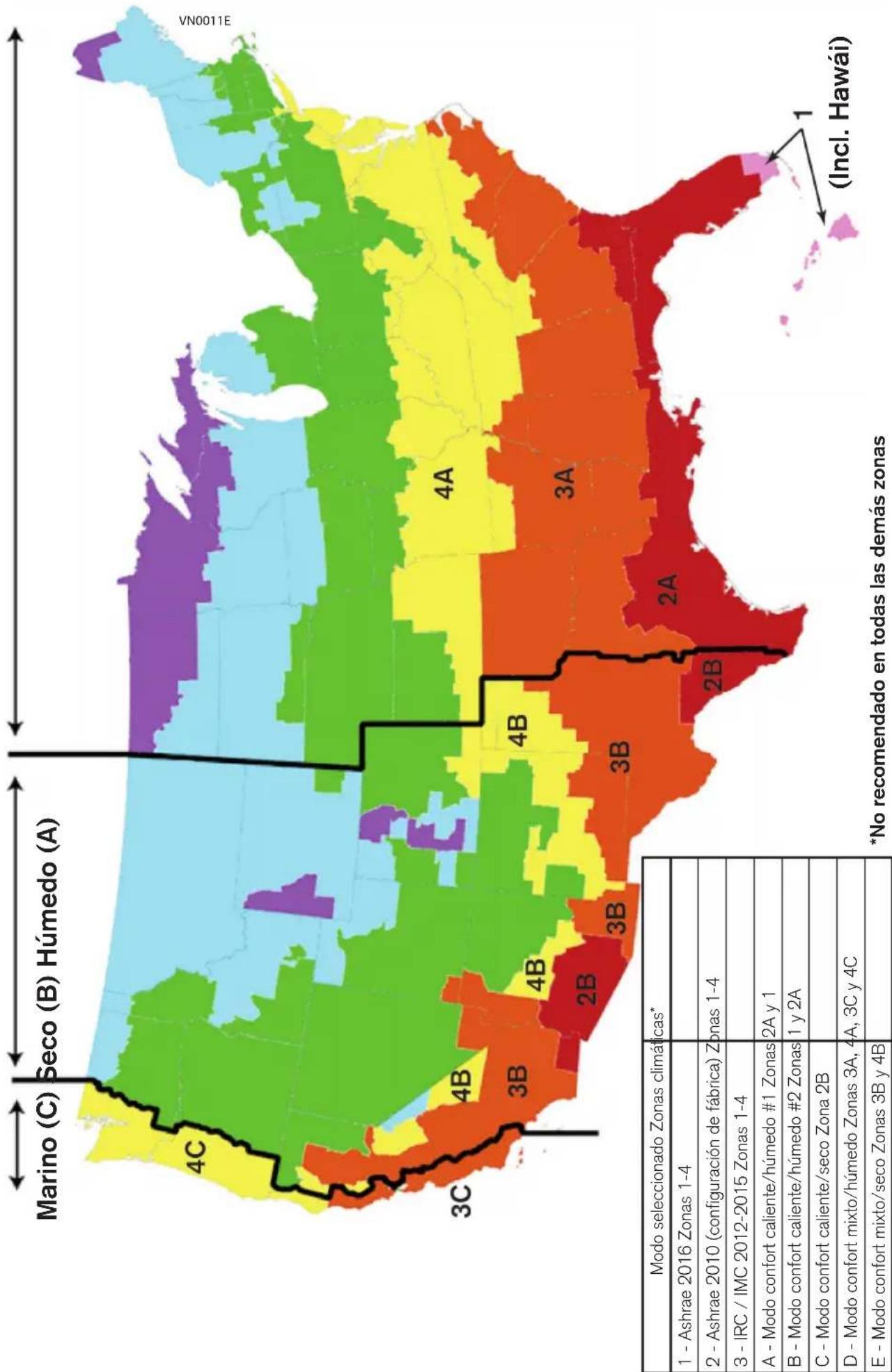
geo
| Region | Mode | Color | |--------|------|-------| | Marino (C) | Húmedo (A) | Yellow | | 4C | | Light Blue | | 3C | | Red | | 4B | | Green | | 3B | | Orange | | 4B | | Yellow | | 2B | | Dark Red | | 3B | | Orange | | 4A | | Yellow | | 3A | | Orange | | 2A | | Red | | 2B | | Dark Red | | 1 (Incl. Hawái) | | Pink | *No recomendado en todas las demás zonas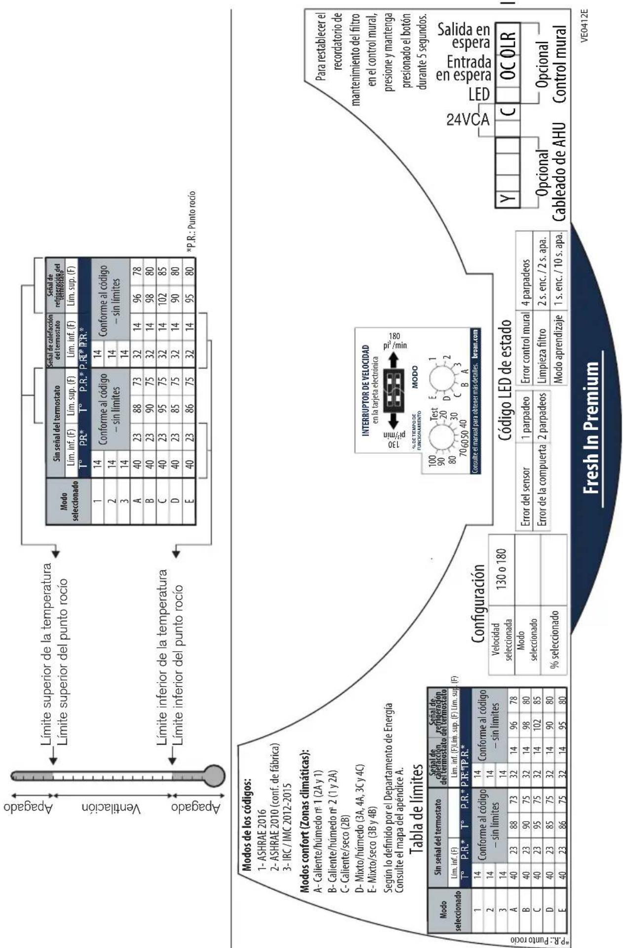
- ⚠️RESIDENTIAL USE ONLY⚠️
- READ AND SAVE THESE INSTRUCTIONS
- ⚠ WARNING
- CAUTION
- TABLE OF CONTENTS
- USER INFORMATION ....4
- PLANNING ....5
- PREPARATION ......6
- HOW TO TEST THE UNIT ......11
- WIRING 12
- SERVICE PARTS ......14
- TROUBLESHOOT ....15
- WARRANTY....18
- APPENDIX A ......19
- APPENDIX B....20
- OPTIONAL WALL CONTROL
- USER SERVICING INSTRUCTIONS
- COMFORT MODE
- PLANNING
- INSTALLATION ZONES
- INSTALLATION TYPES
- Always use insulated ducting of a minimum R-4 insulation factor.
- STAND ALONE INSTALLATION
- INSTALLATION WITH AN AHU
- This unit has to be provided with a low voltage power source (AHU or other), refer to section 5.2 for wiring.
- Make sure that the wire seal foam is put back in place.
- MOUNTING THE UNIT
- FLUSH-TO-CEILING
- UNDER CEILING OR WALL MOUNTED
- CEILING HUNG
- IN THE ATTIC
- Do not install in an attic where the temperature may exceed 160 °F.
- CONNECTING THE INSULATED DUCTS TO THE UNIT
- WARNING
- WIRING AND LOGIC DIAGRAMS
- CONNECTION TO THE AHU
- CONNECTION TO THE VT11W OPTIONAL WALL CONTROL
- HOW TO TEST THE UNIT
- SERVICE PARTS
- Replacement Parts and Repair
- FIN-180P TROUBLESHOOT
- FIN-180P-HW TROUBLESHOOT
- ALL UNITS TROUBLESHOOT
- WARRANTY
- APPENDIX A
- BROAN®
- FRESH IN™ PREMIUM
- FIN-180P y FIN-180P-HW
- ADVERTENCIA
- CÓMO PROBAR EL APARATO
- APÉNDICE A
Brand : BROAN
Model : FIN-180P
Category : Air Conditioning