
WDT950 - Barcode scanners Wasp - Free user manual and instructions
Find the device manual for free WDT950 Wasp in PDF.


| Product Type | Handheld Barcode Scanner / Mobile Computer |
| Model | WDT950 |
| Dimensions | 195 mm x 72 mm x 34 mm |
| Weight | 395 g (with battery) |
| Power Source | Rechargeable Li-ion 3.7V 6700mAh (hot-swappable) |
| Operating System | Android 10 |
| CPU | Qualcomm Snapdragon 720G (Octa-core 2.3 GHz) |
| Memory | 4 GB RAM / 64 GB Flash (expandable via microSD up to 128 GB) |
| Display | 4-inch TFT-LCD WVGA (480x800) capacitive touch, 400 nits |
| Barcode Scanning | 2D Imager (N3603, N6703, EX30) with multi-decode and picklist modes |
| Connectivity | WiFi (802.11a/b/g/n/ac ax-ready, MIMO), Bluetooth 5.1, WWAN (LTE CAT4), GPS, NFC, RFID (UHF/HF) |
| Camera | 13 MP rear with LED flashlight |
| Keypad | 38-key numeric and function keys with backlight |
| Environmental Sealing | IP65 / IP67 |
| Drop Specification | 1.8 m to concrete (2.4 m with bumper) |
| Operating Temperature | -20°C to 50°C |
| Maintenance & Cleaning | Keep connectors free of contaminants; clean with dry cloth; avoid water ingress |
| Safety | Laser Class 2, LED safe, RoHS compliant; FCC/CE certified |
| Spare Parts & Reparability | Battery, hand strap, cradle, screen protector, USB cable; battery replaceable |
| General Information | Supports hot-swap battery up to 1 minute; multiple barcode symbologies; remote management via MoboLink |
Frequently Asked Questions - WDT950 Wasp
User questions about WDT950 Wasp
0 question about this device. Answer the ones you know or ask your own.
Ask a new question about this device
Download the instructions for your Barcode scanners in PDF format for free! Find your manual WDT950 - Wasp and take your electronic device back in hand. On this page are published all the documents necessary for the use of your device. WDT950 by Wasp.
USER MANUAL WDT950 Wasp
Wasp WDT950 Handheld Terminal (38 Keys)


natural_image
Top-down view of a black handheld device with visible ports, buttons, and warning labels (no readable text or symbols beyond basic markings)User's Manual
About This Manual
This manual explains how to install, operate and maintain our product.
No part of this publication may be reproduced or used in any form, or by any electrical or mechanical means, such as photocopying, recording, or information storage and retrieval systems, without permission in writing from the manufacturer. The material in this manual is subject to change without notice.
Regulatory Compliance Statements
FCC Warning Statement
This device has been tested and found to comply with the limits for a Class B digital device, pursuant to part 15 of the FCC rules. These limits are designed to provide reasonable protection against harmful interference in a residential installation. This equipment generates, uses and can radiate radio frequency energy and, if not installed and used in accordance with the instructions, may cause harmful interference with radio communications. However, there is no guarantee that interference will not occur in a particular installation. If this equipment does cause harmful interference with radio or television reception, which can be determined by turning the equipment off and on, the user is encouraged to try to correct the interference by one or more of the following measures:
-
Reorient or relocate the receiving antenna.
—Increase the separation between the equipment and receiver.
-Connect the equipment into an outlet on a circuit different from that to which the receiver is connected.
-Consult the dealer or an experienced radio/TV technician for help. -
This transmitter must not be co-located or operating in conjunction with
any other antenna or transmitter.
- This device complies with FCC RF radiation exposure limits set forth for an uncontrolled environment. To maintain compliance with FCC RF exposure requirements, avoid direct contact to the transmitting antenna during transmitting.
- Any changes or modifications (including the antennas) made to this device that are not expressly approved by the manufacturer may void the user's authority to operate the equipment.
FCC Label Statement
This device complies with part 15 of the FCC rules. Operation is subject to the following two conditions:
- This device may not cause harmful interference.
- This device must accept any interference received, including interference that may cause undesired operation.
RF Radiation Exposure Statement
For body contact during operation, this device has been tested and meets FCC RF exposure guidelines when used with an accessory that contains no metal and that positions the handset a minimum of 1.0 cm from the body.
Use of other accessories may not ensure compliance with FCC RF exposure guidelines.
Canadian Compliance Statement
This device complies with Canada license-exempt RSS standard(s).
Operation is subject to the following two conditions: (1) this device may not cause interference, and (2) this device must accept any interference, including interference that may cause undesired operation of the device.
(i) the device for operation in the band 5150–5250 MHz is only for indoor use to reduce the potential for harmful interference to co-channel mobile satellite systems;
(ii) for devices with detachable antenna(s), the maximum antenna gain permitted for devices in the bands 5250-5350 MHz and 5470-5725 MHz shall be such that the equipment still complies with the e.i.r.p. limit;
(iii) for devices with detachable antenna(s), the maximum antenna gain
permitted for devices in the band 5725-5850 MHz shall be such that the equipment still complies with the e.i.r.p. limits as appropriate; and
(iv) where applicable, antenna type(s), antenna models(s), and worst-case tilt angle(s) necessary to remain compliant with the e.i.r.p. elevation mask requirement set forth in section 6.2.2.3 shall be clearly indicated.
Canada, avis d'Industry Canada (IC)
RF Radio Frequency Exposure Information
The radiated output power of the Wireless Device is below the Industry Canada (IC) radio frequency exposure limits. The Wireless Device should be used in such a manner such that the potential for human contact during normal
operation is minimized.
This device has been evaluated for and shown compliant with the IC Specific Absorption Rate (“SAR”) limits when operated in portable exposure conditions.
European Conformity Statement
Wasp Barcode Technologies herewith declares that the Wasp product is in compliance with the essential requirements and all other provisions of the RED 2014/53/EU directive.
The declaration of conformity is available for download here.
CE RF Exposure Compliance
For body-worn operation, this device has been tested and meets the ICNIRP guidelines and the European Standard EN 62209-2, for use with dedicated accessories, SAR is measured with this device at a separation of 0.5 cm to the body, while transmitting at the highest certified output power level in all frequency bands of this device. Use of other accessories which contain metals may not ensure compliance with ICNIRP exposure guidelines.
CE Mark Warning

RoHS Statement
This device conforms to RoHS (Restriction of Hazardous Substances) European Union regulations that set maximum concentration limits on hazardous materials used in electrical and electronic equipment.
Waste electrical and electronic equipment (WEEE)

natural_image
Symbol of a trash bin with crossed lines indicating no waste or discharge (no text or labels)Wasp has set up a policy and process to meet the 2012/19/EU concerning electronic waste disposal.
For more detailed information of the electronic waste disposal of the products you have purchased from Wasp directly or via Wasp's resellers, you shall either contact your local supplier or visit here.
Taiwan NCC Warning Statement
低功率電波輻射性電機管理辦法
Within the 5.25-5.35 GHz band, U-NII devices will be restricted to indoor operations to reduce any potential for harmful interference to co-channel MSS operations.
Laser Information
The Wasp product is certified in the U.S. to conform to the requirements of DHHS/CDRH 21CFR Subchapter J and to the requirements of IEC 60825-1. Class II and Class 2 products are not considered to be hazardous. The Wasp product contains internally a Visible Laser Diode (VLD) whose emissions do not exceed the maximum limits as set forth in the above regulations. The scanner is designed so that there is no human access to harmful laser light during normal operation, user maintenance or prescribed service operations.
The laser safety warning label required by the DHHS/IEC for the Wasp product's optional laser scanner module is located on the memory compartment cover, on the back of the unit.
* Laser information only applies to the products with laser components.
CAUTION! Use of controls or adjustments or performance of procedures other than those specified herein may result in hazardous laser light. Use of optical instruments with the scanner, including binoculars, microscopes, and magnifying glasses, will increase eye damage. This does not include eyeglasses worn by the user.
LED Information
The Wasp product contains LED indicator(s) or LED ring whose luminance is not harmful to human eyes during normal operation, user maintenance or prescribed service operations.
*LED information only applies to the products with LED components.
Battery Notice
- To guarantee optimal performance, it is recommended that rechargeable batteries be replaced every year, or after 500 charging cycles are completed. It is normal for the battery to balloon or expand after one year or 500 cycles. Although it does not cause damage, it cannot be used again and must be disposed of according to the location's safe battery disposal procedures.
- If a battery performance decreases more than 20%, the battery is at the end of its life cycle. Stop use and ensure the battery is disposed of properly.
- The length of time that a battery lasts depends on the battery type and how the device is used. Conserve the battery life by doing the following:
- Avoid fully uncharging the battery because this places additional strain on it. Several partial uncharges with frequent charges are better than a fully uncharged battery. Charging a partially charged battery does not cause harm to the unit
- DO NOT leave the battery pack or the device in a hot condition such as in a car with the doors closed on a hot day or similar environment, and/or under direct sunlight for an extended period of time. High-temperature conditions might cause battery damaged for further safe usage. Keep the device with the battery within acceptable operating temperatures (please refer to the “specification” section for further details).
To guarantee optimal battery performance, we generally recommend you replace your rechargeable batteries every two years, or after 500 charging cycles. Failure to comply with the above warnings and using the battery neglectfully may lead to critical consequences.
● Do not leave the battery uncharged and unused for an extended
period of time, the battery will wear out and the longevity of the battery will be at least half of one with frequent charges.
- Protect battery life by not over or under charging the battery.
- Please do not leave battery unused for a long time without charging it. Despite Wasp's safety precautions, the battery pack may begin to change shape. If so, stop using it immediately. Please check to see if you are using a proper power adapter to charge the battery or contact your service provider for service.
- If you cannot charge the battery after it has been idle for an extended period of time and it begins to heat up, please do not try to charge it. It may not be functional anymore.
- Please only use the original battery from Wasp. Using a third-party battery can damage our products. Please note that when such damage occurs, it is not covered by Wasp's warranty policy.
CAUTION!
- RISK OF EXPLOSION IF BATTERY IS REPLACED INCORRECTLY. DISPOSE OF USED BATTERIES ACCORDING TO THE INSTRUCTIONS.
Battery charge notice
It is important to consider temperature when the battery pack is charging.
Charging is most efficient at normal room temperature or in a slightly cooler environment. It is essential that batteries are charged within the stated range of 0irc C to 40irc C. Charging batteries outside of the specified range could damage the batteries and shorten their life cycle.
CAUTION! Do not charge batteries at a temperature lower than 0irc C. This will make the batteries unstable and dangerous. Please use a battery temperature detecting device for a charger to ensure a safe charging temperature range.
CAUTION! To ensure the unit works properly, please keep all connectors away from contaminants such as dust, grease, mud, and water. Negligence may cause the unit to lose communication, short circuit, overheat, and so on.
CAUTION! If the connector is damaged, please ensure the connector is fully repaired before use to avoid causing a short circuit.
Storage and safety notice
Although charged batteries may be left unused for several months, their capacity may be depleted due to buildup of internal resistance. If this happens, they will require recharging prior to use. Batteries may be stored at temperatures between -20irc C to 60irc C, however they may deplete more rapidly at higher temperatures. It is recommended to store batteries at room temperature.
* The message above only applies to the usage of the removable batteries. For the products with non-removable batteries / without batteries, please refer to the specification of each product.
Product Operation and Storage Notice
The Wasp product has applicable operation and storage temperature conditions. Please follow the limitation of suggested temperature conditions to avoid failure, damage or malfunction.
*For applicable temperature conditions, please refer to the specification of each product.
Adapter Notice
-
Please do not leave the power adapter in the socket when it is not connected to your Wasp product for charging.
-
Please remove the power adapter when the battery is fully recharged.
-
The bundled power adapter that comes with your Wasp product is not meant to be used outdoors. An adapter exposed to water or rain, or a very humid environment can cause damage to both the adapter and the product.
-
Please only use the bundled power adapter or same specification of adapter to charge your Wasp product. Using the wrong power adapter can damage your Wasp product.
* The message above only applies to the product connected to the adapter. For the products without using the adapters, please refer to the specification of each product.
Hearing Damage Warning
To prevent possible hearing damage, do not listen at high volume levels for long periods.
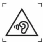
Figure 1 – Warning label (IEC 60417-6044)
Technical Support
Wasp's professional support team is available to quickly answer questions or assist with technical-related issues. Should an equipment problem occur, please contact Wasp technical service.
For more information, visit https://support.waspbarcode.com.
Warranty Policy
The following items covered under the Wasp Limited Warranty are free from defects during normal use:
The warranty period is varied from each country. Please consult with your supplier or Wasp local office for actual length of warranty period to your purchased product.
Warranty becomes void if equipment is modified, improperly installed or used, damaged by accident or neglect, or if any parts are improperly installed or replaced by the user.
Table of Contents
Preface....i
Regulatory Compliance Statements....i
Laser Information ...... vii
LED Information ...... vii
Battery Notice....x
Adapter Notice....x
Hearing Damage Warning....xi
Worldwide Support....xii
Warranty Policy ....xiii
Chapter 1 - Overview....1
1.1 Package .... 1
1.2 Product Detail....2
1.3 Specifications .... 3
1.4 Getting Started ....6
1.5 Keypad Definition ...... 18
Chapter 2 – Installation & Operation ......24
2.1 Barcode Setting....24
2.2 HF Setting 28
2.3 WWAN Setting....30
2.4 WLAN Setting....32
2.6 PAN Setting 37
2.7 GPS Setting....38
2.8 PC Setting 39
2.9 Camera Setting 40
2.10 Performing a Hardware Reset 44
2.11 Performing Factory data reset 45
2.12 KeyRemap....47
2.13 Split Screen....50
2.14 Network Time Protocol (NTP) Server 52
2.15 Battery Swap....54
Chapter 3 – Introduction to Applications....55
3.1 USS (scan service)....55
3.2 File Manager ....59
3.3 Software Update....60
3.4 StageGO 61
3.5 MoboLink....63
Chapter 1 - Overview
1.1 Package
Please make sure the following items are in the WDT950 box.
If something is missing or damaged, please contact your Wasp representative.
The basic package contents
WDT950
Battery
■ Hand Strap
■ Quick Start Guide
■ Regulatory Compliance Statements
Optional accessories
■ Terminal Power Adapter
■ Cradle + Cradle Adapter
■ 1-slot Terminal & Battery Charging Cradle
■ 1-slot Ethernet & Battery Cradle
■ 1-slot USB & Battery Cradle
■ Glass Screen Protector
■ USB Type C Cable
1.2 Product Detail
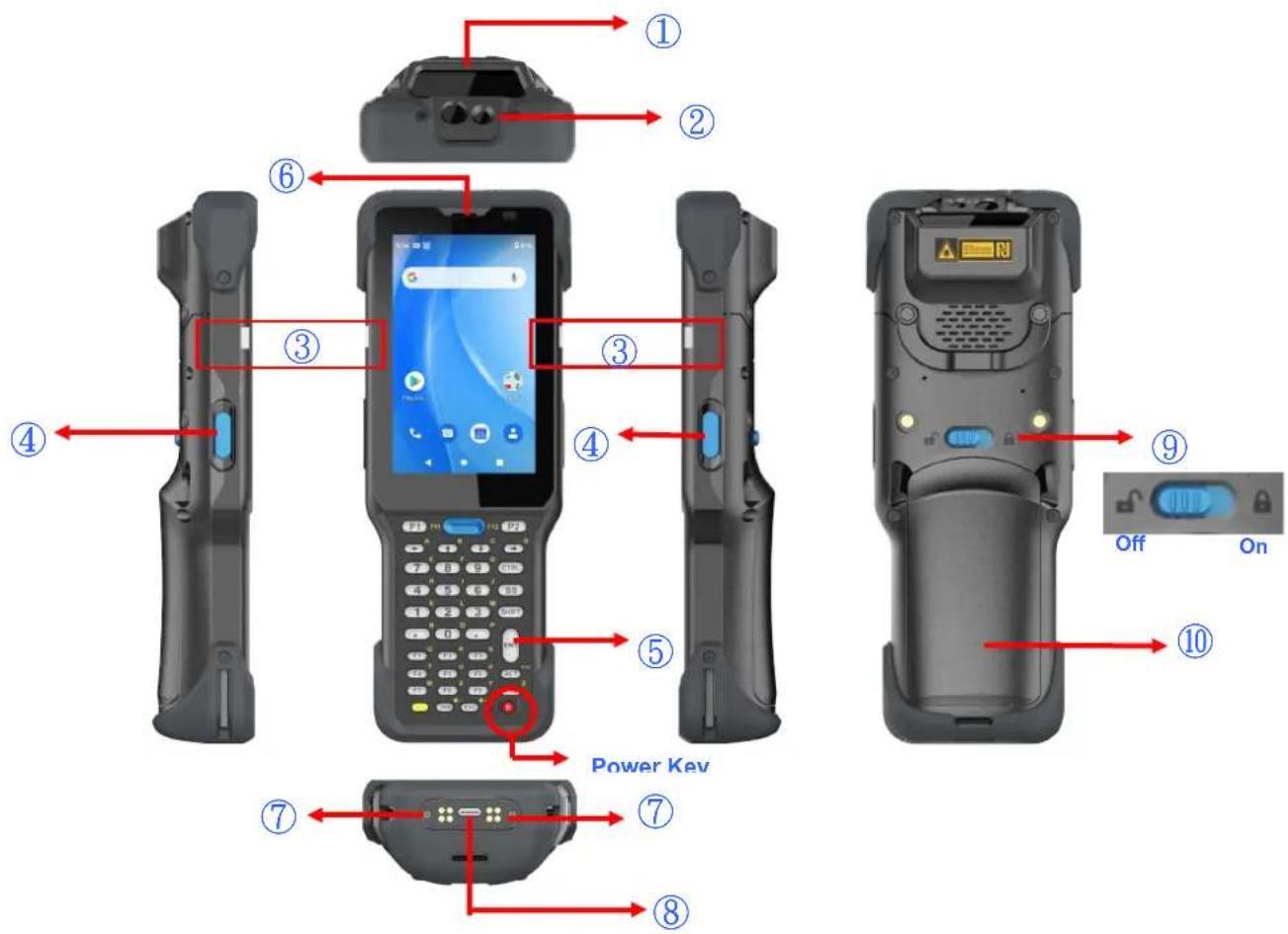
| 1 | Scanner Window | 6 | Receiver |
| 2 | 3m Camera & LED Flashlight | 7 | Pogo pin |
| 3 | LED Indicator | 8 | USB Type C Port |
| 4 | Scanner Trigger Key | 9 | Battery Release Latch |
| 5 | Keypad | 10 | Battery Cover |
1.3 Specifications
| System Features | |
| CPU | Qcta-core 2.3 GHz, Qualcomm 720G (SM7125) |
| Memory 4 GB RAM | 64 GB Flash |
| Expanded slot | Micro SD/TF x 1 (maximum of 128 GB) |
| OS | AndroidTM 10 |
| Languages support | English, Simplified Chinese, Traditional Chinese, Japanese, Spanish, German, French and multiple languages |
| Display | |
| 4"TFT-LCD WVGA (480x800) color screen (400 nits) | |
| Touch Panel | |
| Ultra-sensitive capacitive touch screen, compatible with gloves and support wet resistance | |
| Keypad | |
| Numeric and Function (Default) / Numeric keypad Hard silicon keypad with backlight | |
| Indicator | |
| LED, Speaker, Vibrator | |
| Engines | |
| 2D N3603 | N6703 EX30 |
| Audio | |
| One speaker (8 ohm / 2W output), One receiver (32 ohm), MIC and Headset interface connect to Type-C connector | |
| Regulatory Approvals | |
| CE, RED, FCC, NCC, VCCI, TELEC, CCC, SRRC | |
| I/O Interfaces | |
| USB USB Type-C | Support USB OTG |
| POGO PIN | Custom IO connector (include USB Host) |
| SIM Slot | Nano-SIMx 2 |
| Communication | |
| Camera | 13 MP Rear and Flashlight |
| Bluetooth® | Bluetooth® 5.1 |
| WLAN | 802.11a/b/g/n, 802.11ax-ready, 802.11ac Wave 2(Dual Antenna, MIMO 2X2 support) |
| WWAN | LTE Advanced Support Up to CAT4LTE (FDD) – Bands 1, 2, 3, 4, 5, 7, 8, 17, 20, 28LTE (TDD) – Bands 38, 39, 40, 41UMTS/HSPA+ (3G) – Bands 1, 2, 5, 8GSM/GPRS/EDGE Quad-Band (850/900/1800/1900 MHz) |
| GPS | GPS, GLONASS, Galileo, BeiDou |
| RFID | |
| UHF | Frequency: 865~868MHz, 902~928MHzProtocol: EPC global Class 1 Gen 2 ISO 18000-6C/6BAntenna gain: 3dbiOutput Power: 1-30dbm adjustableData Capture Range: 6~8 meters" |
| HF Frequency 13.56Mhz | ISO14443A/B, ISO15693 standard, NFC, MIFARE, Felica" |
| Power Source | |
| Standard Battery | 3.7V 6700mAh |
| Hot Swap Battery | Keep applications active up to 1 minute |
| Enclosure | |
| Weight | 395g (with battery) |
| Dimension | 195 mm x 72 mm x 34 mm |
| Environmental | |
| Operating Temperature | -4°F to 122°F (-20°C to 50°C) |
| Storage Temperature | -22°F to 140°F (-30°C to 60°C) |
| Charging Temperature | 32°F to 113°F (0°C to 45°C) |
| Relative Humidity | 5% ~ 95% (non-condensing) |
| Drop test to Concrete 1.8m | 2.4m (with Bumper) |
| ESD | +/-8KV direct discharge, +/-15KV air discharge |
| Environmental Sealing | IP65 / IP67 |
Note:
The device is restricted to indoor use only when operating in the 5150 to 5350 MHz frequency range.
 | AT | BE | BG | HR | CY | CZ | DK |
| EE | FI | FR | DE | EL | HU | IE | |
| IT | LV | LT | LU | MT | NL | PL | |
| PT | RO | SK | SI | ES | SE | UK | |
| IS | LI | NO | CH | TR |
1.4 Getting Started
1.4.1 Install / Remove the Battery Cover
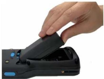
■ Install the battery pack and the battery cover
- Slide and position the battery pack, making sure the battery contacts are aligned with the contacts in the battery compartment.
natural_image
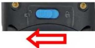
Hand inserting a black device into a black device with control buttons (no visible text or symbols)- Make sure the battery release latch is in the unlocked position.
natural_image
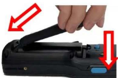
Close-up of a black remote control with a blue indicator light and red double-headed arrow (no text or symbols)- Insert the battery cover up to 45 degrees ( 45irc ), from bottom to top. Press the battery cover down to secure in place and then slide the battery release latch to the locked position.
natural_image
Close-up of a hand holding a black device with red arrows pointing to the handle (no text or symbols visible)
natural_image
Close-up of a black electronic device's front panel with a blue indicator and red arrow pointing to the right (no text or symbols visible)■ Remove the battery cover and the battery
There are two ways to remove the battery, the following is the first method.
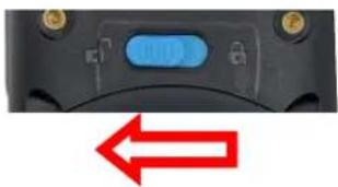
- Make sure the battery release latch is in the unlocked position.

natural_image
Close-up of a black electronic device with a blue control knob and a red double-headed arrow below (no text or symbols)- Grab the battery cover from the two recesses and lift gently upward to remove the battery cover.

natural_image
Close-up of hands holding a black remote control device with red arrows pointing to the buttons (no text or symbols visible)- There are two ways to remove the battery. First one is by pulling the pull tab in the battery compartment to remove the battery. Make sure the pull tab stays inside of the battery compartment when closing the cover.

natural_image
Close-up of a hand inserting a black cable into a device, with a red X mark indicating cancellation (no text or symbols present)WARNING! There is a risk of fire and burns if the battery is handled improperly. DO NOT disassemble, crush, puncture, short external contacts, or dispose the battery pack in fire or water. DO NOT attempt to open or service the battery. Dispose of used batteries according to local recycling guidelines in your area.
NOTE: After installing the battery, make sure the battery cover is securely closed.
The second way to remove the battery is shown as follows:
- Make sure the battery release latch is in the unlocked position.
natural_image
Close-up of a black electronic device with a blue control knob and red double-headed arrow below (no text or symbols)- Grab the battery cover from the two recesses and gently lift upward, stop when you feel a resistive force. Press the battery cover against the battery and lift the battery upwards until you remove the battery. (The process follows the principle of lever).

natural_image
Three-step illustration showing hands using a remote control device to adjust the device (no text or symbols visible)1.4.2 Charging the Battery
Using the terminal for the first time, you need to charge it for about 24 hours. For the regular use, you can charge the terminal with the USB type-C cable. It takes within 4 hours to charge the terminal with the cradle to full capacity.
Connect the type C USB cable to the USB port on WDT950 and connect the other end of the USB cable to AC power adapter. Then plug into the electrical outlet. It is highly recommended that using the USB type-C cable and AC power adapter to charge the terminal.
The charging LED indicator on WDT950 turns red when it is in charging state. The green light is on after the battery is fully charged.

natural_image
Diagram showing a device rear panel connected to an electrical outlet via a cable, with a red arrow indicating the process (no text or symbols present)1.4.3 Turning on the terminal for the first time
It is recommended to fully charge WDT950 before first use. You can now start up your device to set up the languages, WLAN setting, and date and time.
Power Button
Turn ON your device by pressing the power button on the terminal.

1.4.4 Checking the LED status
| Terminal | LED | Description |
| Red Light | ■ Battery Charging■ Twinkling together to indicate battery low status (less than 15%) when power on.■ Twinkling alternate to indicate battery is not installed or not installed well when battery charger was plugged in. | |
| Green Light | ■ Battery Fully charged■ Barcode scan good read | |
| Blue Light Message | ||
| No LED (Red and Green) display when battery is out. | ||
Checking the Battery Status
If the battery level becomes low in the course of normal use, a status icon appears on the device screen indicating low or very low battery status. In both cases, please back up your data, and then recharge your device as soon as possible.
1.4.5 Using the Micro SD/ Nano SIM Card
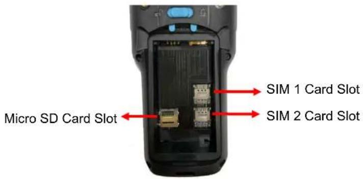
The WDT950 has 1 x micro SD and 2 x nano SIM card slots inside the battery compartment.
Note: Please TURN OFF the terminal, before inserting or removing micro SD card or nano SIM card.
Inserting Micro SD/ Nano SIM Card
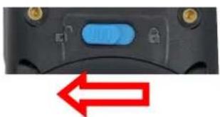
- Make sure the battery release latch is in the unlocked position.
natural_image
Close-up of a black remote control with a blue indicator button and red double-headed arrow (no text or symbols)- Grab the battery cover from the two recesses and lift gently upward to remove it. Remove the battery by pulling the pull tab.

natural_image
Two black handheld devices with red arrows pointing to their control buttons, one being inserted and the other holding a clip (no text or symbols visible)Wasp WDT950 (38 keys) User's Manual
3.
SIM 1 & 2 Card Slot
Push down SIM card holder to unlock and lift the card holder to insert SIM card. Close the card holder and slide up to lock position. Ensure that it is installed properly.

MicroSD Card Slot
Push up MicroSD card holder to unlock and lift the card holder to insert MicroSD card. Close the card holder and slide down to lock position. Ensure that it is installed properly.

- Replace the battery back and the battery cover and lock the cover. Make sure the battery cover is securely closed.
Checking WDT950 storage
Please go to Settings

and tap Storage to check the WDT950 storage.

1.4.6 Battery Status
The WDT950 provides battery info for users to check the battery status, history view and also set up user preferences.
- On the main screen, scroll the screen from down to top to reach the APPS,
and tap

Settings and then tap BatteryInfo.
- BatteryInfo shows the details of the battery use.
Wasp WDT950 (38 keys) User's Manual

1.4.7 BatteryInfo Health Service
BatteryInfo health service information will display on both WDT950 lock screen and the notification bar.
■ When the battery health is higher than 80% :

■ When the battery health is higher than 60%:

■ When the battery health is lower than 60% : (Battery should be replaced)

Note: If the battery is stored for the long term, it might result in accelerated battery health lower. Please try to charge and discharge your batteries several times and check the battery health is at a steady rate. If the battery health is still lower than 60%, the battery should be replaced
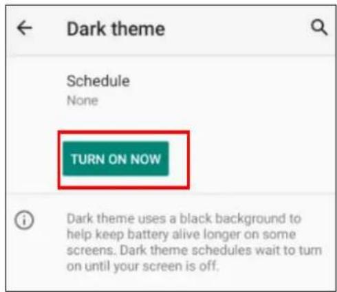
1.4.8 How To Enable Dark Theme
Dark mode is a feature that allows you to switch to the dark theme of an app or an entire desktop operating system.
- On the main screen, scroll the screen from down to top to reach the APPS,

and tap
Settings and then tap Display.
- Tap Dark theme or tap the button on the right to enable the dark mode.

OR
1.4.9 How To Enable Night Light
Night Light is a feature that allows you to activate night light in order to reduce your eyestrain.
On the main screen, scroll the screen from down to top to reach the APPS, and
tap Settings and then tap Display.
1.5 Keypad Definition

| Key Description | |
 | Power key |
 | Press the yellow alpha key to access the alternate alpha characters. Toggle between numeric and alphabetic entry modes. The icon appears on the Status bar. Press and release the orange alpha key again to return to the default keypad functions. |
 | Programmable key |
 | Scan key |
 | Moves right, up, down, or left from one item to another. |
| Key Description | ||
 | Numeric/Alpha keysPress the yellow alpha key to access the alternate alpha characters. Toggle between numeric and alphabetic entry modes. | |
 F10 F10 | Special function keys | |
 | CTRL key | |
 | Backspace key | |
 | SHIFT key | |
 | Enter key | |
 | ALT key | |
 | TAB key | |
 | ESC key | |
| Key Description | ||
 | Produces a period symbol | |
 | Produces a comma symbol | |
1.5.1 Using Keypad Combination
Press the yellow key, it will appear as symbol A in the status bar at the top of the screen. Then you can refer to the following table to execute the desired function or input.
When it's alpha mode, LED indicates solid yellow light.

| Key | Yellow Key + Key |
| P1 | F11 |
| P2 F12 | |
| Left Arrow A | |
| Up Arrow B | |
| Down Arrow C | |
| Right Arrow D | |
| ESC |  |
| TAB |  |
| ALT Space | |
| CTRL CTRL | |
| ENT | ENT |
| 7 E | |
| 8 | F |
| 9 G | |
| BS BS | |
| 4 H | |
| 5 | I |
| 6 J | |
| 1 K | |
| 2 L | |
| 3 | M |
| , N | |
| 0 | O |
| . P | |
| F1 Q | |
| F2 R | |
| F3 | S |
| F4 T | |
| F5 | U |
| F6 V | |
| F7 W | |
| F8 X | |
| F9 | Y |
| F10 Z |
Chapter 2 - Installation & Operation
2.1 Barcode Setting
- On the main screen, scroll the screen from down to top to reach the APPS,
and tap Settings Settings and then tap USS (scan service). Or from the notification bar tap USS (scan service).

- You now enter the scan service application.
2.1.1 Settings
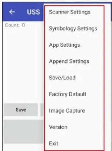
- Please tap ☐ on the screen to see all the settings of USS.
2.1.2 Barcode Scan
- Please tap Start Scan to get ready for barcodes scan service.

- For Save / Load Settings, and Factory Default,
Please tap and then tap Save / Load Settings, and Factory Default.

- To save settings, you can also tap Save on the screen and input path then tap OK.
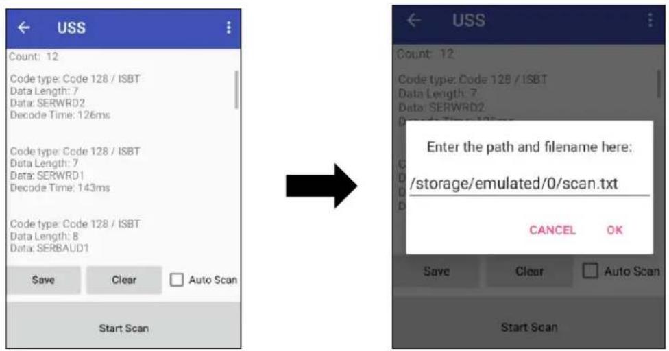
The saved data is stored in File Manager. (Please see 3.2 File Manager)

2.2 HF Setting
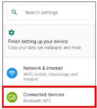
- On the main screen, scroll the screen from down to top to reach the APPS,
and tap

Settings
Settings and then tap Connected devices.
- Tap Connection Preferences to enable NFC



- Make sure that both devices are unlocked and have NFC turned on. Also make sure that the NFC antenna area of WDT950 and the other devices' NFC area are close to one another. Slightly moving the phones until a connection is made. Tap the screen.

natural_image
Top-down view of a black handheld device with a red circle highlighting a warning symbol (no text or labels visible)2.3 WWAN Setting
- Turn off the terminal to insert the SIM card.
Note : ■ For the instruction, please refer to 1.4.5 Using the Micro SD/ Nano SIM Card.
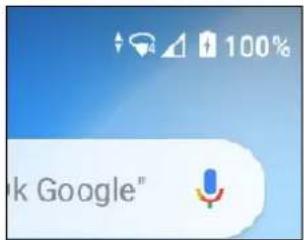
- Turn on the terminal, 4G signal will show at the top of the screen.
2.3.1 Mobile Network Settings
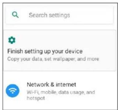
- On the main screen, scroll the screen from down to top to reach the APPS,

Settings and then tap Network & internet.
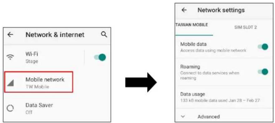
2. Tap Mobile network for more network settings.
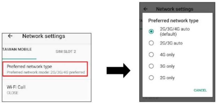
3. To choose different network type, please tap Preferred network type.
2.4 WLAN Setting
- On the main screen, scroll the screen from down to top to reach the APPS,
and tap

Settings
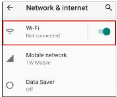
Settings and then tap Network & internet.

- To see available networks, turn WLAN ON. And tap to choose the available networks.
- Choose the available networks, and enter the Password and tap Connect.
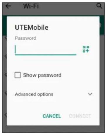
-
If the wireless network that you want is not listed, tap + Add network to manually add it.
-
When enabled, the icon is displayed on the status bar.
2.5.1 WLAN Advanced
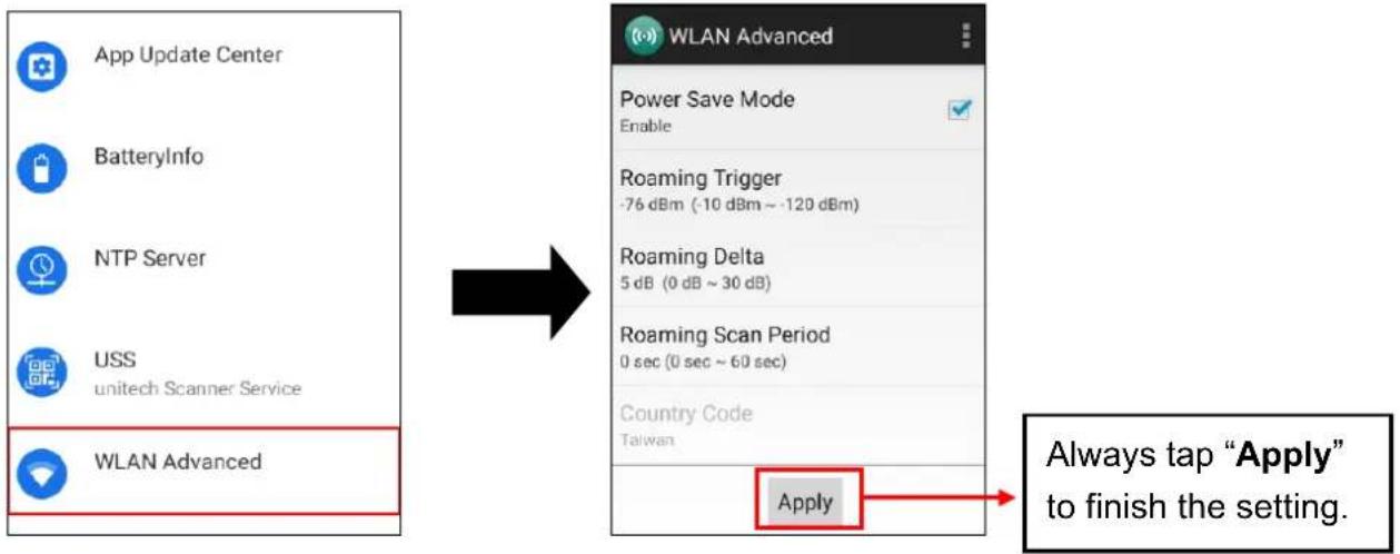
WLAN advanced can enhance the roaming behavior when the device is in areas of particularly low coverage or losing its connection to the network infrastructure and provides the power save mode to control the power consumption setting.
WLAN advanced will help users to manage the seamless roaming.
- On the main screen, scroll the screen from down to top to reach the APPS,
and tap

Settings and then tap WLAN Advanced.
flowchart
graph LR
    A["App Update Center"] --> B["BatteryInfo"]
    B --> C["NTP Server"]
    C --> D["USS\nunitech Scanner Service"]
    D --> E["WLAN Advanced"]

    F["WLAN Advanced"] --> G["Power Save Mode\nEnable"]
    G --> H["Roaming Trigger\n-76 dBm (-10 dBm ~ -120 dBm)"]
    H --> I["Roaming Delta\n5 dB (0 dB ~ 30 dB)"]
    I --> J["Roaming Scan Period\n0 sec (0 sec ~ 60 sec)"]
    J --> K["Country Code\nTaiwan"]
    K --> L["Apply"]

    M["Always tap "Apply" to finish the setting."] --> L
• Power Save Mode
Tap to enable the power save mode to set the WLAN module to its optimum power consumption setting.
- Roaming Trigger (Default: -76 dBm, Range: -10 dBm \~ -120 dBm)
Roaming trigger will help users to look for a better and stronger signal strength (in dBm) by scanning many access points. When the signal strength is lower than roaming trigger value, roaming trigger will start to look for better access points.

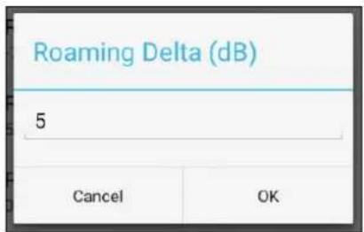
- Roaming Delta (Default: 5 dB, Range: 0 dB \~ 30 dB)
Based on roaming delta value, the device will roam to a better signal strength access point.
- Roaming Scan Period (Default: 0 sec, Range: 0 sec \~ 60 sec)
The device will stay with the current AP based on the roam period value before it roams to a different AP.

2.5.1.1 Other options
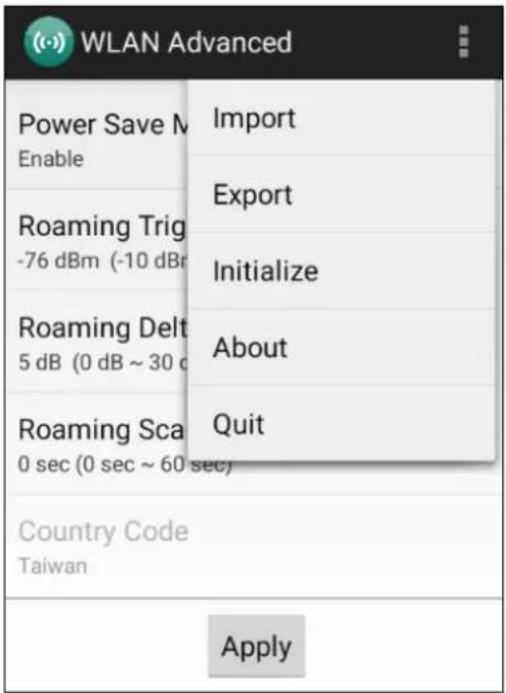
Tap for more options to import / export the current data from the device. Initialize can restore the default settings.
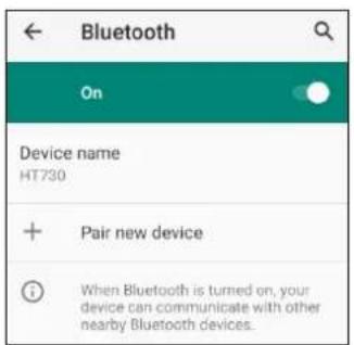
2.6 PAN Setting
- On the main screen, scroll the screen from down to top to reach the APPS,
and tap Settings and then tap Connected devices.

- Tap Connection Preferences to enable Bluetooth

- Tap ON / OFF to enable / disable Bluetooth ® .
To pair the available device, turn Bluetooth® ON to choose the available device.
2.7 GPS Setting
- On the main screen, scroll the screen from down to top to reach the APPS,
and tap

Settings and then tap Location.

- Tap the bar for the permission to use your location information.

2.8 PC Setting
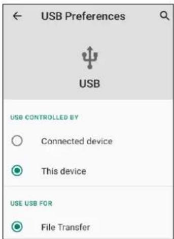
- Connect WDT950 to your computer with the USB type C cable. Your computer will recognize it is USB charging.

natural_image
Illustration of a laptop with an open screen and a blue arrow pointing to a USB cable (no text or symbols present)- Slide down from top, the system will show the following picture, then you can select File transfers.
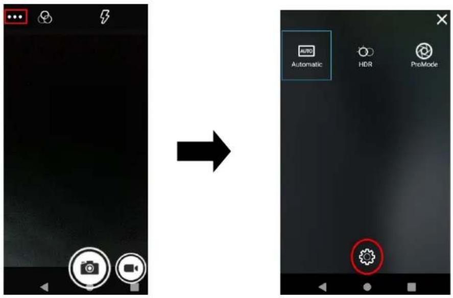
2.9 Camera Setting
- Scroll the screen from down to top to reach the APPS,
and tap Camera.


natural_image
Front view of a gray electronic device with a red directional arrow pointing right (no text or symbols)13m Camera & LED Flashlight
2.9.1 Camera Settings
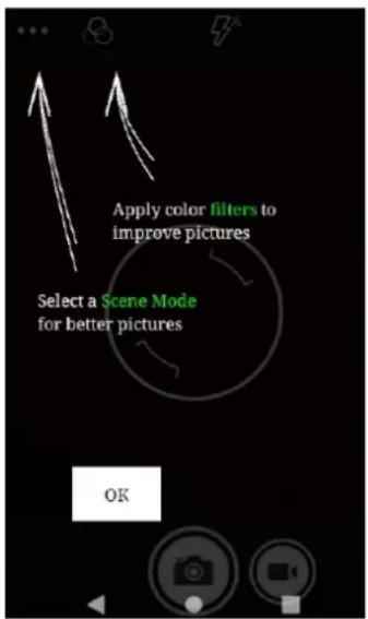
For the first time turn on, the screen will show a brief introduction about camera settings.
2.9.2 Scene Mode Setting

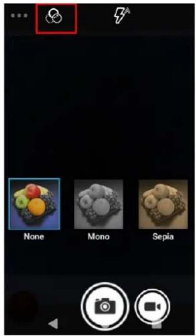
2.9.3 Camera filter effects
2.9.4 Settings
Please tap Enter the settings section.
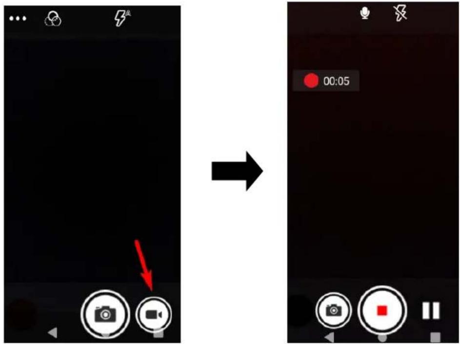
2.9.5 Record Videos
Once tap the record button, it will start recording.
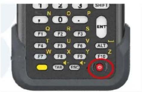
2.10 Performing a Hardware Reset
You may have to perform a reset if the device freezes (i.e., the terminal no longer responds to the buttons or tapping on the screen).
Long press and hold the Power button around 10 seconds to shut down the system and then press the Power button again to turn on the device.
2.11 Performing Factory data reset
- On the main screen, scroll the screen from down to top to reach the APPS,
and tap

Settings and then tap System.

- Tap Advanced for more options, and then tap Reset options.

- You can reset the system on Reset options.
When you select Erase all data (factory reset), it will erase all folders.

2.12 KeyRemap
The WDT950's keys can be programmed for users to be able to perform different functions or applications.
Six options to use key remap functions: SCAN_LEFT, SCAN_RIGHT, SCAN_KEY, PROG_1, PROG_2 and TRIGGER_GUN
2.12.1 Remap a key
On the main screen, scroll the screen from down to top to reach the APPS, and
tap KeyRemap. Select the keys to remap and enable key.

2.12.2 Export / Import a remap Key Configuration file
■ Export file
1. Tap

2. Select Export

The remap Key configuration can be exported to a text file or imported into WDT950.
Note: The configuration file (keys_config.txt) is saved in File Manager.
(For File Manager setting, please refer to 3.2 File Manager)

■ Import file
Before importing the file, please make sure the configuration file (keys_config.txt) is in File Manager.

-
Tap
-
Select Import

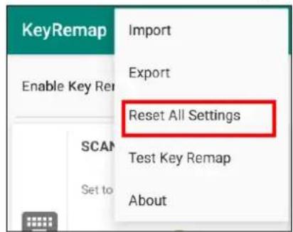
■ Reset all settings
- Tap

- Select Reset all settings
2.13 Split Screen
Split screen function allows you to have two apps work side by side on the same screen. Please follow the steps to enable split screen multitasking.
Note: Some apps may not work with split-screen.
- Tap Background APP button until you see those background apps on the screen.
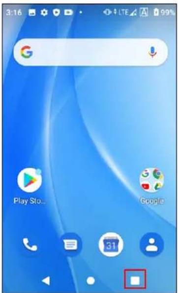
- Tap and hold the thumbnail and then select "Split screen." First APP "Split screen" will be on top of the screen. For another APP to show on the bottom half of the screen, simply tap on the APP thumbnail.

flowchart
graph LR
    A["Location Pin"] --> B["Split Screen"]
    B --> C["Search..."]
    C --> D["Internal Storage: Total 12.00 GB Available 11.13 GB"]
    D --> E["Podcasts: 0 items, Ringtones: 0 items"]
- To cancel split screen, simply drag up or down the black bar in the middle of the two APPs to expand the app that you would like to keep in full screen.
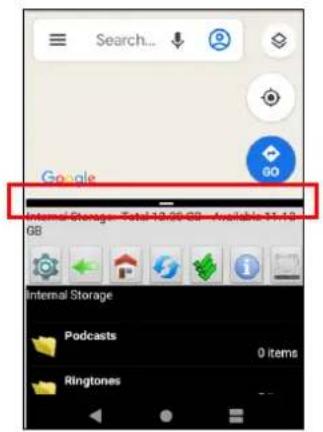
2.14 Network Time Protocol (NTP) Server
The Network Time Protocol is used to synchronize the clocks over the Internet. Allow the users to set the clock by using NTP Server.
- On the main screen, scroll the screen from down to top to reach the APPS,
and tap

Settings and then tap NTP (Network Time Protocol)
Server.

- On NTP Server, choose the system preferences to set up network time.

2.15 Battery Swap
Please follow the steps for the battery swap.
- When the battery release latch switches to the unlocked position, the screen will show the countdown window (within 59 secs) for the users to change the battery.

- When the battery swap is done, you can start to use the terminal without restarting it again.
Note : Please see 1.4.1 Installing the Battery for more battery change information.
Chapter 3 – Introduction to Applications
3.1 USS (scan service)
- On the main screen, scroll the screen from down to top to reach the APPS,
and tap Settings Settings and then tap USS (scan service).
Or from the notification bar to tap USS (scan service).
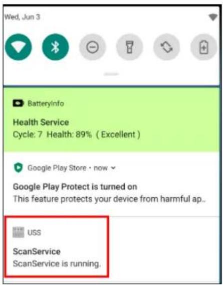
- You are now using the scan service application.
3.1.1 How to scan
- There are 3 ways to scan the barcodes: Trigger keys on the sides, Scan key on the keyboard or tap Start Scan on this App.
- Aim the Barcode Scan Engine to the barcode.
- After scanning the barcodes, the barcode information is as shown below.
- To save the scanned data, tap Save and enter the path and filename, then tap OK.

3.1.2 Multi Decode Scan Mode
Multi decode scan function allows users to scan multiple barcodes at once.
- Tap ☐, Choose Scanner Settings
- Enable Multi Decode Mode, and input the barcode decode count (up to 10 counts) and start multi decode scan.

3.1.3 Picklist Mode
Picklist mode enables WDT950 to decode only barcodes that are aligned under the laser crosshair or LED aiming dot.
For picklist mode demonstration, please click on the this YouTube channel for more information: https://www.youtube.com/watch?v=QiT2E6hxD_k
- Tap ☐, Choose Scanner Settings
- Enable Picklist Mode and allows users to easily select and scan a single or specific barcode from a field of barcodes.

3.1.4 More information about USS
For more information about USS, please download the document from the below link:
http://w3.tw.ute.com/pub/cs/manual/uss/USS-RA-1-MANUAL_en20210326.pdf
3.2 File Manager
On the main screen, scroll the screen from down to top to reach the APPS, and
tap

File Manager.


: Settings

: Return to the previous page

: Main page

: Refresh

: Folder arrangement

Folder Information

: Flash Storage
3.3 Software Update
- On the main screen, scroll the screen from down to top to reach the APPS,
and tap Software Update.

- To update or check the latest version of each application, please tap CHECK UPDATE.
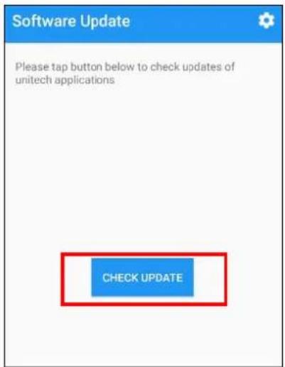
- Tap for more settings on Software Update.

3.4 StageGO
StageGO is a configuration staging solution for Wasp mobile devices. StageGO helps IT admins use the 1-click auto configure feature to set up and initialize a device quickly. Devices configure themselves by using configuration scripts and barcodes prepared by the IT admins, the StageGO app, currently available for Android devices, uses Wasp devices' barcode scanning capabilities to load the script barcode into the device and start the self-configuration process.
■ Using StageGO to configure a device in 3 simple steps:


Step 1. Edit Script:
IT admins can prepare a configuration script by using StageGO's web-based script editor. For more information, please visit :
https://www.ute.com/en/products/detail/stagego
Step 2. Print Barcodes:
Upon completion of editing a script, IT admins may either download the script file or generate barcodes that represent the entire script. The script file or the barcode printouts can then be handed over to the device users for scanning.
Step 3. Scan Barcodes:
When device users receive the barcode printouts (or the script file) from the IT admins, they can then run the StageGO app on the terminals, scan all the barcodes on the printouts (or load the script file). When all barcodes are scanned, StageGO is ready to begin self-configuration. StageGO can also be configured for 1-click auto configuration. On the main screen, scroll the screen

from down to top to reach the APPS, and tap
StageGO.
Please visit the StageGo website for more information :
https://apps.ute.com/StageGO2/
3.5 MoboLink
MoboLink is a software platform that helps customers to remote manage their purchased devices and applications. The core of the MoboLink platform provides functionalities in the MDM (Mobile Device Management) and MAM (Mobile Application Management) domains, and then further extends into other management functions such as alert notification management and account management.
On the main screen, scroll the screen from down to top to reach the APPS, and


3.5.1 More about MoboLink
For detailed operation, solution and usage, please refer to the website: https://www.ute.com/en/products/detail/MoboLink



- Wasp WDT950 Handheld Terminal (38 Keys)
- User's Manual
- About This Manual
- Regulatory Compliance Statements
- FCC Warning Statement
- FCC Label Statement
- RF Radiation Exposure Statement
- Canadian Compliance Statement
- Canada, avis d'Industry Canada (IC)
- RF Radio Frequency Exposure Information
- European Conformity Statement
- CE RF Exposure Compliance
- CE Mark Warning
- RoHS Statement
- Waste electrical and electronic equipment (WEEE)
- Taiwan NCC Warning Statement
- 低功率電波輻射性電機管理辦法
- Laser Information
- LED Information
- Battery Notice
- CAUTION!
- Battery charge notice
- Storage and safety notice
- Product Operation and Storage Notice
- Adapter Notice
- Hearing Damage Warning
- Technical Support
- Warranty Policy
- Table of Contents
- Preface....i
- Chapter 1 - Overview....1
- Chapter 2 – Installation & Operation ......24
- Chapter 3 – Introduction to Applications....55
- Chapter 1 - Overview
- Package
- The basic package contents
- Optional accessories
- Product Detail
- Specifications
- Note:
- Getting Started
- Install / Remove the Battery Cover
- ■ Remove the battery cover and the battery
- Charging the Battery
- Turning on the terminal for the first time
- Power Button
- Checking the LED status
- Checking the Battery Status
- Using the Micro SD/ Nano SIM Card
- Inserting Micro SD/ Nano SIM Card
- SIM 1 & 2 Card Slot
- MicroSD Card Slot
- Checking WDT950 storage
- Battery Status
- BatteryInfo Health Service
- How To Enable Dark Theme
- How To Enable Night Light
- Keypad Definition
- Using Keypad Combination
- Chapter 2 - Installation & Operation
- Barcode Setting
- Settings
- Barcode Scan
- HF Setting
- WWAN Setting
- Mobile Network Settings
- Tap Mobile network for more network settings.
- To choose different network type, please tap Preferred network type.
- WLAN Setting
- WLAN Advanced
- • Power Save Mode
- - Roaming Trigger (Default: -76 dBm, Range: -10 dBm \~ -120 dBm)
- - Roaming Delta (Default: 5 dB, Range: 0 dB \~ 30 dB)
- - Roaming Scan Period (Default: 0 sec, Range: 0 sec \~ 60 sec)
- Other options
- PAN Setting
- GPS Setting
- PC Setting
- Camera Setting
- Camera Settings
- Scene Mode Setting
- Camera filter effects
- Settings
- Record Videos
- Performing a Hardware Reset
- Performing Factory data reset
- KeyRemap
- Remap a key
- Export / Import a remap Key Configuration file
- ■ Export file
- Tap
- Select Export
- ■ Import file
- ■ Reset all settings
- Split Screen
- Network Time Protocol (NTP) Server
- Battery Swap
- Chapter 3 – Introduction to Applications
- USS (scan service)
- How to scan
- Multi Decode Scan Mode
- Picklist Mode
- More information about USS
- File Manager
- Software Update
- StageGO
- Step 1. Edit Script:
- Step 2. Print Barcodes:
- Step 3. Scan Barcodes:
- MoboLink
- More about MoboLink
Brand : Wasp
Model : WDT950
Category : Barcode scanners